Premium levella PRF32405XW User manual

Ser vice Manual
(PRF32405XW/
PRF32406XS)

CONTENTS
PARTS IDENTIFICATION ............................................................................................................................1
REFRIGERATION CIRCUIT ..........................................................................................................................2
CIRCUIT DIAGRAM....................................................................................................................................3
SAFETY PRECAUTIONS .............................................................................................................................4-5
USING INTRODUCTION ............................................................................................................................6-8
DISASSEMBLY COMMON PARTS OF FREEZER ……………………….……...............………….................………….......…9-18
◆DOOR REVERSAL INSTRUCTIONS
◆CARE & MAINTENANCE
◆Checking the compressor and replacing PTC and Overload protector
◆Checking the thermostat and replacing thermostat
EXPLODED VIEW ......................................................................................................................................19
TROUBLESHOOTING........ .........................................................................................................................20

PARTS IDENTIFICATION
FEATURES
1. Freezer Compartment with Door
2. Thermostat Dial and Push Button Defrost
3. Drip Tray
4. Plastic Coated Shelves
5. Magnetic Gasket: Tight fitting door seal keeps all the
cooling power locked inside.
6. CANSTOR: Holds 355ml cans of pop, juice, or beer.
7. Bottle Rack: For tall, small and medium cans or jars.
8. Leveling Leg: Adjust so the unit is level.
Page 1
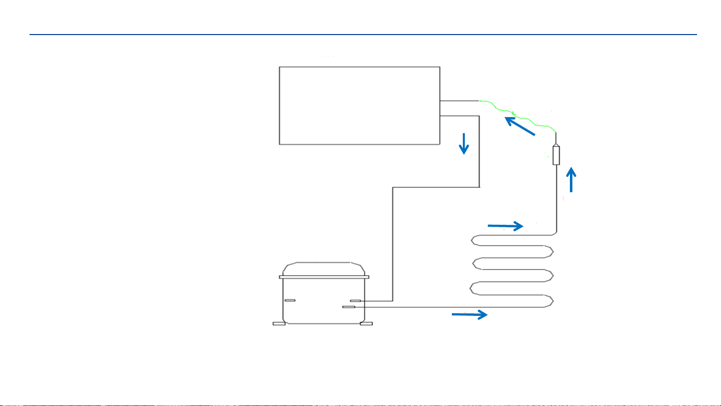
REFRIGERATION CIRCUIT
Basic refrigeration schematic
Page 2
evaporator
capillary
filter
Condenser
compressor
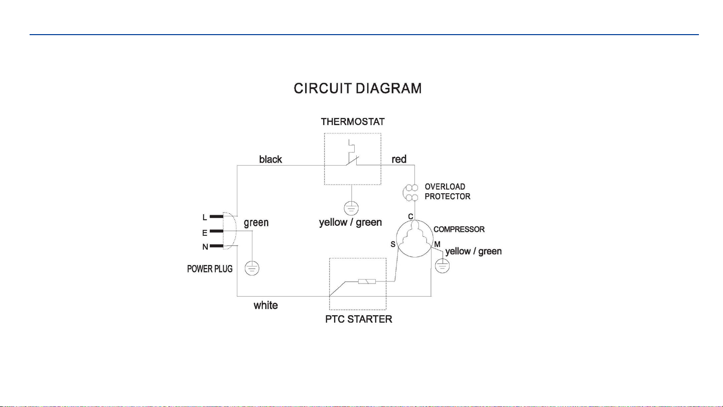
CIRCUIT DIAGRAM Page 3

SAFETY PRECAUTIONS
SAFETY REQUIREMENTS
DANGER: Risk of fire or explosion. Flammable refrigerant used. Do not puncture refrigerant tubing.
•Do not use mechanical devices to defrost refrigerator.
•Ensure that servicing is done by factory authorized service personnel, to minimize product damage or safety issues.
•If the power supply cord is damaged, it must be replaced by the manufacturer, its service agent or similar qualified person in order to avoid
hazard.
•Consult repair manual or owner’s guide before attempting to service this product. All safety precautions must be followed.
• Dispose of properly in accordance with federal or local regulations.
•Follow handling instructions carefully.
•Do not store explosive substances such as aerosol cans with a fl ammable propellant in this appliance.
WARNING: Keep ventilation openings, in the appliance enclosure or in the built-in structure, clear of obstruction.
WARNING: Do not use mechanical devices or other means to accelerate the defrosting process, other than those recommended by the
manufacturer.
WARNING: Do not damage the refrigerant circuit.
WARNING: Do not use electrical appliances inside the food storage compartments of the appliance,unless they are of the type recommended
by the manufacturer.
CAUTION: Children should be supervised to ensure that they do not play with the appliance.
DANGER: Risk of child entrapment. Before throwing
away an old appliance:
• Remove the door or lid.
•Leave shelves in place so that children may not easily climb inside.
DANGER: Do not add a lock to the door or lid. This can cause child entrapment and harm.
Page 4

SAFETY PRECAUTIONS
SAFETY REQUIREMENTS
This appliance is not intended for use by persons (including children) whose physical, sensory or mental capabilities may be different or
reduced, or who lack experience or knowledge, unless such persons receive supervision or training to operate the appliance by a person
responsible for their safety.
This appliance is intended to be used in household and similar applications such as:
• Staff kitchen areas in shops, offi ces and other working environments;
• Farm houses and by clients in hotels, motels and other residential type environments;
• Bed and breakfast type environments;
• Catering and similar non-retail applications.
GROUNDING INSTRUCTIONS
This appliance must be grounded. Grounding reduces the risk of electrical shock by providing an escape wire for the electrical current.
This appliance has a cord that has a grounding wire with a 3-prong plug. The power cord must be plugged into an outlet that is properly
grounded. If the outlet is a 2-prong wall outlet, it must be replaced with a properly grounded 3-prong wall outlet. The serial rating plate
indicates the voltage and frequency the appliance is designed for.
WARNING - Improper use of the grounding plug can result in a risk of electric shock. Consult a qualified electrician or service agent if the
grounding instructions are not completely understood, or if doubt exists as to whether the appliance is properly grounded.
Do not connect your appliance to extension cords or together with another appliance in the same wall outlet. Do not splice the power
cord.Do not under any circumstances cut or remove the third ground prong from the power cord. Do not use extension cords or ungrounded
(two prongs) adapters.
Page 5

USING INTRODUCTION
LOCATION
• Two people should be used when moving the appliance.
• Remove interior and exterior packaging prior to installation. Wipe the outside of the appliance with a soft, dry cloth and the inside with a
lukewarm wet cloth.
• Place the appliance on a fl oor that is strong enough to support it when it is fully loaded.
• Do not place the appliance in direct sunlight or near sources of heat, such as a stove or heater, as this can increase electrical consumption.
Extreme cold ambient temperatures may also cause the appliance to perform improperly.
• Do not use the appliance near water, for example in a wet basement or near a sink.
• This appliance is intended for household use only. It is not designed for outside installation, including anywhere that is not temperature
controlled (garages, porches, vehicles, etc.).
• Before connecting the appliance to a power source, let it stand upright for approximately 6 hours. This will reduce the possibility of a
malfunction in the cooling system from handling during transportation.
• This appliance is 44.9 cm (17.7 inches) wide by 83.3 cm (32.8 inches) high by 47 cm (18.5 inches) deep.
• Allow 12.7 cm (5 inches) of space between the back, sides and top of the appliance and all adjacent walls.
• This appliance is intended for free-standing installation only and is not intended to be built into a cabinet or counter. Building in this
appliance can cause it to malfunction.
IMPORTANT
Ensure that the door is fully closed when the appliance is in operation. Failure to fully close the door can lead to excessive condensation and
potential water damage to fl ooring under the appliance.
Page 6

USING INTRODUCTION
TEMPERATURE SELECTION
The temperature of the appliance can be adjusted by turning the thermostat
dial.
The thicker, darker part of the blue line is the coldest setting.
The thinner, lighter part of the blue line is the warmest setting.
The “O” position will turn off the cooling function.
Internal temperature of the appliance can vary based on ambient temperature,
the quantity of items stored and how frequently the door is opened.
Page 7
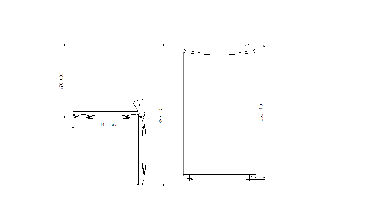
USING INTRODUCTION
OUTER DIMENSIONS
Page 8
DISASSEMBLY COMMON PARTS OF FREEZER
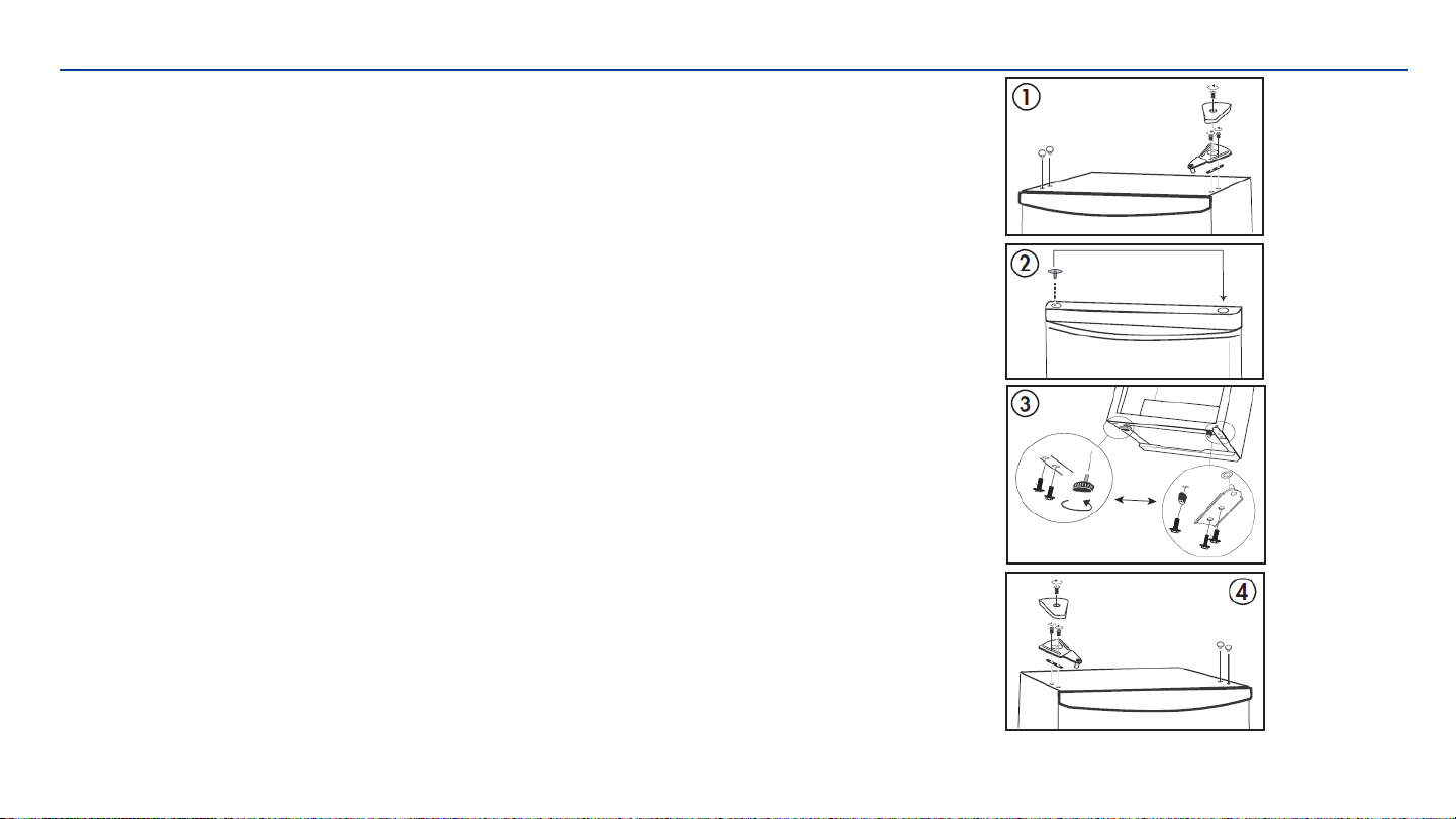
DOOR REVERSAL INSTRUCTIONS
If the appliance is placed on its back or side for any length of time during this process, it
must be allowed to remain upright for 6 hours before plugging it in to avoid damage to
the internal components.
1. Remove the hinge cover and the upper hinge. Remove the hinge hole covers from the
top left side of the cabinet. Remove the door from the cabinet.
2. Remove the hinge hole cover from the top left side of the door and place it in the
hinge hole on the top right side of the door.
3. Remove the adjustable foot from the bottom left side of the cabinet and remove the
solid foot and lower hinge from the bottom right side of the cabinet. Install the lower
hinge and solid foot on the bottom left side of the cabinet and install the adjustable foot
on the bottom right side of the cabinet.
4. Place the door on the cabinet and install the upper hinge on the top left side of the
cabinet. Before tightening the screws in the upper hinge, ensure that the top of the door
is level with the top of the cabinet and that the rubber gasket is making a good seal with
the cabinet all the way around. Install the hinge cover over the hinge and install the hinge
hole covers in the screw holes on the top right side of the cabinet.
Page 9

DISASSEMBLY COMMON PARTS OF FREEZER
CARE & MAINTENANCE
CLEANING
Ensure the appliance is unplugged before cleaning.
• To clean the inside of the appliance, use a soft cloth and a solution of a tablespoon of baking soda to one quart
of water or a mild soap solution or some mild detergent.
• Wash removable shelves in a mild detergent solution, then dry and wipe with a soft cloth.
• Clean the outside with a soft, damp cloth and some mild detergent.
• It is important to keep the area clean where the door seals against the cabinet. Clean this area with a soapy
cloth. Rinse with a damp cloth and let dry.
Note: Do not use cleaners containing ammonia or alcohol on the appliance. Ammonia or alcohol can damage the
appearance of the appliance. Never use any commercial or abrasive cleaners or sharp objects on any part of the
appliance.
Page 10

DISASSEMBLY COMMON PARTS OF FREEZER
CARE & MAINTENANCE
POWER FAILURE
Most power failures are corrected within a few hours and should not affect the temperature of your
appliance if you minimize the number of times the door is opened. If the power is going to be off for
a longer period of time, take the proper steps to protect your contents.
Note: Wait 3 to 5 minutes before attempting to restart the refrigerator if operation has been interrupted.
VACATION
• Short vacations: Leave the appliance operating during vacations of less than three weeks.
• Long vacations: If the appliance will not be used for several months, remove all items and turn
off the appliance. Clean and dry the interior thoroughly. To prevent odor and mold growth,
leave the door open slightly, blocking it open if necessary.
Page 11

DISASSEMBLY COMMON PARTS OF FREEZER
CARE & MAINTENANCE
MOVING
• Make sure the appliance is empty.
• Secure the shelves with tape.
• Secure the door with tape.
• Turn the adjustable foot up to the base to avoid damage.
• Protect the outside of the appliance with a blanket or similar item.
• Be sure the appliance stays in the upright position during transportation.
• If the appliance is placed on its back or side during transportation, upon reaching the destination, allow it to
remain upright for 6 hours before plugging in to avoid damage to internal components.
DISPOSAL
This appliance may not be treated as regular household waste, it should be taken to the appropriate waste
collection point for recycling of electrical components. For information on local waste collection points, contact
your local wasteremoval agency or government office.
Page 12
DISASSEMBLY COMMON PARTS OF FREEZER
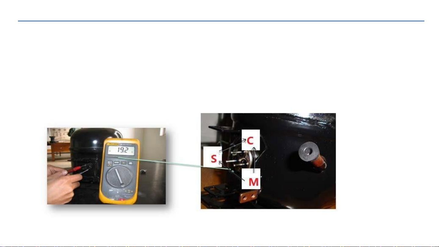
Checking the compressor
After the compressor is powered on separately, the compressor does not start and exhaust.
Use a multi-meter to test the resistance between C & M, C&S and S&M :
Normal range of C&M : About 8.76~11.85Ω
Normal range of C&S : About 7.48~10.12Ω
Normal range of S&M : About 16.24~21.97Ω
If the test result is not in this range then it means the inner coil has some problem and the compressor cannot work
properly.
Page 13

DISASSEMBLY COMMON PARTS OF FREEZER
Checking the compressor accessory
Remove the combined PTC starter and overload protector
Page 14
model : ZHB54-120P4.7 A

DISASSEMBLY COMMON PARTS OF FREEZER
Checking the compressor accessory
Compressor Protector test ——
Use a multi-meter to test the resistance between the two terminals as the pic show :
If there show 000 or almost 0 then it is OK.
If there is no response then it is broken.
model : ZHB54-120P4.7 A
Page 15

DISASSEMBLY COMMON PARTS OF FREEZER
Checking the compressor accessory
Compressor PTC starter test ——
Use a multi-meter to test the resistance between the two terminals as the pic show
If there show the number is between about 3.7-5.7 then it is OK.
If there show 000 or no response then it is broken.
After the replacement of the combined PTC starter and overload protector,
the compressor still does not start.
If there is no exhaust, the compressor is fault.
model : ZHB54-120P4.7 A
Page 16

DISASSEMBLY COMMON PARTS OF FREEZER
The instruction of replacing PTC and Overload protector
1.Remove the fastening screws
2.Remove the Compressor Wire Clamp Screw
and Compressor Wire Clamp
3.Remove the cover
4.Replace the combined PTC starter and
overload protector
Page 17

DISASSEMBLY COMMON PARTS OF FREEZER
Checking the thermostat
Page 18
The instruction of replacing thermostat
Use a multi-meter to check the C-L terminal is on or off.
1.Remove the Evaporator door
2.Remove the tapping screw 4×16
3.Remove the thermostat assembly and replace the thermostat
Evaporator door
thermostat assembly
Tapping Screw 4×16
This manual suits for next models
1
Table of contents
Other Premium levella Refrigerator manuals


