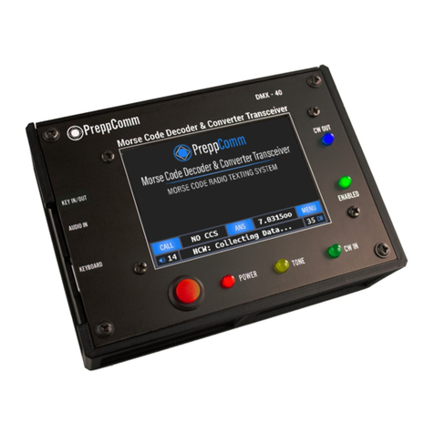
PreppComm DMX-40 User manual

Making Communications Fun Again!
DMX-40
REFERENCE MANUAL
By Eric C Anderson
PreppComm
Version 3.1, December 2020
Copyright © 2020 PreppComm. All rights reserved.!

Return to Table of Contents
Table of Contents
Title Page 1
Table of C o nt e nt s 2
1. Overview 5
2. Warranty and Cautions 7
1. Important Notice 7
2. The Elephant in the Room 8
3. Getting Started... Quickly 8
3. Getting Acquainted 10
4. Initial Setup 13
5. Setup with External Transceiver 14
6. Power On Walk-Thru 15
7. Menus 18
1. Local Station Setup 19
2. VFO Adjust 21
3. Typing Speed 22
4. Microprogramming 24
5. MHz Memories 25
8. Keyboard Controls 27
1. Receive Mode Keyboard Controls 27
2. Decoder Mode Control Key 28
3. Gain Control Key 29
4. Editing Keys 30
5. Frequency Control and Tuning 30
6. RIT Tuning 31
7. Frequency Memories & Frequency Memory Editor 32
8. Function Keys 34
9. Transmit Keyboard Controls 34
9. Decoder Operation 36
1. HCW Mode 36
2. CTX Mode 37
3. Switching Modes 38
4. Tuning a Station 38
5. Two Frequencies? 40
6. The Tuning Rule 41
7. Switching Bands (Modes) 41
10. Tone Output Control and KEY IN 43
Copyright © 2020 PreppComm
Page 2

Return to Table of Contents
11. CALLING 44
1. Before We Begin... 44
2. General Calling 44
3. Setting Transmit Speed 45
4. Setting a New Default Transmit Speed 46
5. The CALL Sequence 47
6. Setting Up a Directed Call 47
7. Three Ways for Establishing a CCS 49
8. What Happens After You CALL? 50
12. ANSWERING 51
1. The ANSwer Validate and ANSwer Microprogram 52
2. The ANSwer Validate Component 53
3. The ANSwer Start Component 53
4. The Pop-Up Type-Ahead Buffer 54
5. Sending Your Message 56
6. The ANSwer Ending Component 56
7. The INFO Microprogram 57
8. What Happens After an ANSWER? 57
13. Receiving Using RIT Tuning 59
1. Activating RIT 59
2. Deactivating RIT 61
14. Appendix 1: Pro-Signs and No-Signs 62
15. Appendix II: Special Characters 63
16. Appendix III: Calibrating your VFO 64
17. Appendix IV: Terminology 66
18. Appendix V: RPL and User Microprograms 68
1. Introduction 68
2. Built-In Microprograms 69
3. Microprogram Types 70
4. RPL Control Characters 70
5. Built-In Microprogram Review 73
6. Inserting into a Running CALL or ANS Microprogram 75
7. The Microprogram Editor 76
8. Microprogram Help 78
9. Some Examples 79
19. Appendix VI: Keyboard and RPL Layouts 81
1. Receive Mode Keyboard Layout 82
2. Transmit Mode Keyboard Layout 83
3. RPL Command Table Page 1 84
4. RPL Command Table Page 2 85
Copyright © 2020 PreppComm
Page 3

Return to Table of Contents
1. Overview
Congratulations for purchasing the new DMX-40 Morse Code Decoder & Converter
Transceiver! The DMX-40 was created to make it possible and easy for non-technical
people to utilize the HF (High Frequency) Amateur Radio bands for battery-powered
emergency communications. This is done by providing a texting interface to the user,
making communications via Morse code similar to texting on a modern smartphone:
simple, easy, and fun! It also provides a fantastic platform for learning Morse Code,
should the operator have the interest in doing so."
The DMX-40 transceivers are easy to operate, due to its graphical user interface,
presented on a 3.5" color touchscreen display. In addition, an included USB/PS2
keyboard is utilized to provide text input as well as control functions."
While the transceiver can be seen as a simple tool for non-technical operators, it also
includes many advanced features often not found in much more expensive equipment:"
1. Automatic code speed setting: transmitter speed set from received code speed"
2. Hyper-active tone extractor and powerful digital filter to extract text in high-
noise situations, with extreme noise immunity"
3. Super selective decoder (120 Hz wide sensitivity) without audio filtering - you
hear full 100 - 10,000 Hz audio, but the decoder only hears a tiny slice around
the set tone frequency."
4. Auto limits on transmit frequency based on license levels - impossible to
transmit on unlicensed frequencies"
5. Automatic capture of remote station call letters"
6. Built-in typing speed calibration to limit transmit speed to your comfortable
speed, to prevent starving the transmitter while transmitting"
7. 76 character type-ahead pop-up buffer for keeping ahead of the transmitter and
correcting mistakes before they go out"
8. Built-in microprograms for calling, answering, and sending information"
9. 12 User definable microprograms for customizing operational modes and
messages, using a powerful microprogramming language"
10. Full function microprogram editor"
11. Word wrap display for easy reading of incoming and outgoing text."
Thus, for the more advanced user, the DMX-40 transceiver can provide an excellent
choice for portable operation, due to its very small size and light weight It can also
easily be placed into an EMP protective container for the purpose of having it available
in case of an EMP event, as well. This is one of the features of our Professional
Station GO bag."
Copyright © 2020 PreppComm
Page 5

Return to Table of Contents
Using the Reference Manual
The manual is written sequentially for you to go through and learn how to use your
transceiver. It is also designed as a reference manual, by including all relevant
information under any given topic."
Several Appendices are provided at the end of the manual with keyboard layout
diagrams and other tables that can be copied or printed out to use to support the
learning process. Also a terminology appendix is included in case you need help with
any terms you don’t understand."
Under the Hood
For those of you with technical interest, the DMX-40 is based on a triple-processor
real-time multi-tasking system architecture. A complex dance of real-time interaction
between three interrupt-driven real-time processors makes the magic of the DMX-40
possible. The receiver is a Direct Conversion Synchrodyne design, with a balanced
mixer front-end."
Cross-linked Reference
This manual is provided as a PDF document with many cross-links. Specifically, the
Table of Contents links to each section, and there is a link at the top of every page to
return to the Table of Contents. Likewise, whenever a reference is made to another
section for more information, a link is provided. This makes finding information much
easier. Of course the PDF file may also be printed, but then you lose the cross-linking
feature. We will work on inventing a way for links to work on paper documents... :)"
Copyright © 2020 PreppComm
Page 6

Return to Table of Contents
2. Warranty and Cautions
The warranty for this unit is against defects in material and workmanship for a period of
one year. Properly ground the DMX transceiver before transmitting, especially
when the humidity is low and you are getting static shocks from doorknobs, etc. Use
either the ground of the SMA antenna connector or a corner screw on the top panel as
your ground point."
2.1 Important Notice: Things Not Covered by the Warranty!
1. Operating your DMX-40 transceiver without a dummy load or properly
designed and installed 40 meter antenna can cause failure of your transmitter PA
(Power Amplifier), and void your warranty. We recommend an SWR of 3.0 or less.$
2. Operating your DMX-40 transceiver at more than 16 volts also voids the
warranty. This can cause failure of the transmitter Power Amplifier.$
3. Carefully align and plug connectors - do not force. The side mounted USB and
audio connectors are mounted on the rear surface of the front panel printed circuit
board. They can be broken offfrom the circuit board if excessive force is used
when plugging in a cable. This type of damage is not covered by the warranty.$
4. Do not scratch or gouge the touch screen with a sharp object. The touch
screen is not like the capacitive touch screen on your cell phone, but rather a less
expensive resistive touch panel. This means it requires a little more force, and that
there is a thin plastic layer with invisible wires over the glass. It can be cut with
sharp objects, which will disable all or part of the touch function. Also, too much
pressure on the screen can crack the glass, which can also cause touch failure and
ultimately LCD failure. Use a rounded tip or eraser end of a pencil if you want to
avoid fingerprints. Use the included microfiber cloth to clean offfingerprints. You
can also create microprograms to replace pressing some of the buttons on the
Main Screen if you wish so they can be accessed directly from your keyboard.
Finally, use the lid provided to protect the front panel and LCD when not in use.
Physical damage to the front panel, such as damaged LCD, or damaged LED’s is
not covered under the warranty.$
5. Take care how you run the keyboard cable. The keyboard cable can act as an
antenna and pick up RF from the transmitter, especially if you have RF in the shack.
A low SWR antenna with a good ground or a balanced antenna with a 1:1 Balun will
eliminate most RF in the shack problems. Keep the keyboard cable away from the
rear of the DMX-40, and coil it up at the rear of the keyboard to shorten it (use a
tight coil) to reduce RF issues. There is an RF filter inside, but you can overpower it
and cause your DMX to lose it’s mind when you transmit.$
Copyright © 2020 PreppComm
Page 7

Return to Table of Contents
$
TROUBLESHOOTING TIP: If your transceiver starts acting weird, the first thing to
check is the keyboard wire. If RF gets into the computer "brains" it can cause
some very strange behavior! Fix the problem by locating the wire away from the
RF, and reboot the transceiver."
2.2 The Elephant(s) In The Room"
The Big Elephant: that would be the antenna. Yes, you need an antenna, and no,
you can’t use a "rubber duck" or vertical whip antenna on virtually any of the HF bands
except maybe 10 meters and expect good results. For example, for the DMX-40, a 40
meter band unit, this means you need a 40 meter capable antenna. Since you will be
running QRP (low power on transmit), having an efficient antenna is pretty important.
While we are not going to go into great detail here (this is not the place for an antenna
tutorial), please get some help from other amateur radio operators in selecting and
installing a good antenna (if you don’t know how to do it yourself). Antenna kits are
available and range from inexpensive to very expensive, but selecting the right one for
your situation that will work well for QRP (there it is again: low power operation) and
getting it installed properly will save you loads of headaches - and grant you loads of
contacts! For portable operation, the PreppComm Professional Station GO Bag
includes an easy to install 40 meter end-fed antenna, but it is not designed for
permanent installations."
No, this is not a walkie-talkie, but then, you can communicate worldwide directly with
the DMX transceiver, no repeaters, no internet, no nothing, just you and your
transceiver and your antenna. That is what a good antenna will get you. So don’t
ignore the elephant in the room: get yourself a good antenna, and if that means GET
HELP!"
The "Other" Elephant is ... experience. Once you have it, you can quickly tune around
the band. But there is some expertise you will gain over time on adjusting the decoder
gain, and the frequency, determining which of the two sides of the signal you are on,
and selecting the correct one. And being aware of band conditions, which are related
to time of day, sunspots, and other factors. Do not be disappointed if you don’t make
any contact on your first try! You are not running a 1000 watt station with a 150 foot
tower! Patience and practice are very important."
If you have a buddy across town, or across the valley that has a similar rig, that is a
great way to start. That way, you can learn the ropes with someone you can talk to
over the phone if things are not working the way you expected. So, initially, finding a
local ham operator with Morse Code experience, or someone with an DMX-40 of their
own to get some on-the-air experience with is an excellent way to gain confidence and
experience."
Copyright © 2020 PreppComm
Page 8

Return to Table of Contents
2.3. Getting Started... Quickly"
We have provided a Quick Start Guide (separate file) to enable you to get started quickly with
your new transceiver. We recommend using that as a starting point, and then using this
Reference Manual to fill in the gaps in your knowledge of the various functions and features
that are not covered in the Guide. We have included many cross links within the document, as
well as Table of Contents links and a back link at the top of every page to get you back to the
Table of Contents with a single click. This greatly enhances exploring the contents of the
manual."
As mentioned before, there are a number of appendices that you should check out early on.
We recommend you print out the keyboard command charts, for example, to have next to you
as you are learning how to use the various features of your new transceiver. At first, that might
seem to be a daunting task, but practice a little, and it will become second nature."
As always, we love to hear from our customers, so if you have questions, comments, or
suggestions, please use the Contact Us page on our website:"
https://PreppComm.com
Copyright © 2020 PreppComm
Page 9

Return to Table of Contents
3. Getting Acquainted
Figure 1 is a labeled diagram of the DMX-40 transceiver:"
FIGURE 1. DMX-40 TRANSCEIVER
3.5" Color LCD Display
At the center is the 3.5" color LCD display, which is also a touch screen input device. "
Key In/Out Jack!
This is a stereo 3.5mm jack that has one channel dedicated to Key Out, when used
with an external transceiver (External Mode). The other channel is dedicated to
support a Morse Code key for manual code entry for training and on-air use, if desired.
See Appendix X for a wiring diagram.
Audio In Jack
The Audio In jack is used to connect the audio output from an external rig to the
internal decoder (External Mode)."
Copyright © 2020 PreppComm
Page 10

Return to Table of Contents
USB Keyboard
This is a USB-A female connector for connecting the included USB/PS2 keyboard to
the DMX-40."
CW Out LED
This blue LED displays the outgoing Morse Code when the transceiver is in transmit
mode (either with or without an internal transceiver)."
Enabled LED
This green LED indicates when you have set the frequency to one you are allowed to
transmit on, based on the license level you have specified in local station setup. If the
unit is in External Mode, the LED is always lit, and it is up to you to manage your
external rig."
CW In LED
This green LED indicates what the computer is seeing as Morse Code input. It
represents the considered opinion of a complex set of analog and digital filters, and is
a very accurate representation of the incoming Morse Code signal. This LED is used to
assist tuning the receiver to center on the frequency of the sender."
Tone LED
This yellow LED indicates the output of just the analog portion of the filtering system.
This LED is normally flickering from noise, as well as lighting brightly during a strong
signal. This LED is helpful for adjusting the decoder gain correctly. Decoder gain is
controlled from the keyboard."
Power LED
This LED is lit when the power is applied to the internal circuitry."
Power Switch
This is a push-on/push-offpower switch for controlling the power to the unit. Normally,"
Headphone Jack
The headphone 3.5mm jack is located on the rear panel of the transceiver. Headphone
volume is adjusted from the keyboard."
Antenna Connector
The antenna connector is a female SMA connector, and is located on the rear panel of
the transceiver. And yes, an antenna for the band you will be operating on, or a
dummy load is essential. For best results, do not use a car antenna as they are
extremely inefficient (less than 1% efficiency, typically). Rather, use a dipole, end-fed,
or NVIS antenna designed for 40 meters."
12V Power Connector (Not Shown), Power Consumption and Output Power
Copyright © 2020 PreppComm
Page 11

Return to Table of Contents
The 12V power connector is located on the rear panel of the
transceiver. A 12V adaptor plug with screw terminals (as shown,
right) is supplied with your unit. This allows you to wire a battery to
plug into the 12V connector. The power connector can be
connected to a 12V ½amp or greater power supply that has a 2.1 x
5.5mm plug on it, or to a 12 volt battery capable of supplying up to ½
amps of power (peak load) via the adaptor. Typical receiver current is 80-120 ma, and
for transmit peak is from 380 to 430 ma at 12V power supply voltage. Average power
consumption (receive & transmit) is about 2 watts. RF power output is about 2.7W at
12V. Note: Some 12V wall plug power supplies generate a LOT of RF noise. Others
are poorly filtered, so you will hear 120 Hz hum. Working offa battery is the best way
to eliminate these problems."
The unit can operate at 13.8V as well, where power output rises to 3.5W. If you have a
regulated power supply, 16V will give you 4.2W RF output. Maximum recommended
voltage is 16 volts, but only with a well-regulated power supply. Factory tests have
gone up to 18 volts, but if damage occurs because you have exceeded 16 Volts, it is
not covered on the warranty."
Ground Connector
(Not Shown). Any radio transceiver or transmitter requires a good ground to operate
properly, and to prevent RF (Radio Frequency) energy from backing up to the unit via
the antenna cable, which can cause minor shocks or burns to the operator. Be sure to
properly ground your transceiver before using it with anything other than a dummy
load. A good antenna with a low SWR (Standing Wave Ratio) will generally eliminate
any RF in the shack issues. See more on grounding below."
WARNING: Operating the transmitter without a properly
installed antenna or dummy load may damage your
transmitter, and will void your warranty.
Copyright © 2020 PreppComm
Page 12

Return to Table of Contents
4. Initial Setup
The standard setup for the DMX-40 is shown below. A dummy load is an optional
alternative to a 40 meter antenna, or using External Mode, but allows you to fully
operate the transceiver without causing any band interference, and without an antenna.
A 5W dummy load can be purchased on Amazon for about $7. Note that an antenna/
rig ground wire is not shown."
FIGURE 2: STANDARD TX/RX SETUP
An alternative to the headphones is a powered speaker. These can be purchased for
as little as $16 on Amazon. If you purchased the Professional Station GO Bag, it
comes with a great set of earphones."
Copyright © 2020 PreppComm
Page 13

Return to Table of Contents
5. Setup with an External Transceiver
If you plan to use the DMX-40 as a decoder and encoder for a different transceiver,
typically a multi-band 100 watt transceiver, for example, use Figure 3 below."
FIGURE 3: EXTERNAL MODE SETUP FOR DMX-40
Again, here you can replace the earphones with a powered speaker. A 3.5mm splitter
cable, available for a few dollars at Amazon, can provide the connection between your
external transceiver headphone output, your headphones or powered speaker, and the
audio input to the DMX-40 audio in jack. Key Out from the KEY IN/OUT jack requires
correct wiring. See Appendix X for wiring diagram. This connects to your external
transceiver KEY IN jack, and can handle up to 12V."
IMPORTANT NOTE: when operating the external rig DO NOT USE THE CW FILTER!
Use the SSB filter. Otherwise you will find the decoder not able to operate. The
decoder is looking for a signal at around 1300 Hz, which is well within the 300 - 2700
Hz typical filter range of an SSB audio filter, but NOT within the 300 Hz bandwidth of a
typical CW filter."
Copyright © 2020 PreppComm
Page 14

Return to Table of Contents
6. Power On Walk Through
Once you have set up your transceiver, press the Power switch, you will immediately
see the splash screen appear, as shown in Figure 4:"
FIGURE 4: SPLASH SCREEN
This screen will be present for a few seconds, and will then be followed by the Main
Screen, shown in Figure 5. Each item on this screen is described below."
FIGURE 5: MAIN SCREEN
Text Area
Most of the screen is dedicated for text - both for received text from other stations, and
transmitted text from you. The initial screen shows the PreppComm logo, but this will
Copyright © 2020 PreppComm
Page 15

Return to Table of Contents
disappear as soon as the space is needed. Text you transmit is shown in blue. Text
you receive is shown in gray. The text area is 37 characters wide and 10 lines high, and
is fully word-wrapped - i.e., automatic wrapping to the next line always occurs on word
boundaries for easy reading. You cannot directly type into this space: only the
encoder (transmitter) and the decoder (receiver) can place text here. Of course you do
type most outgoing encoder text for the transmitter, but that first appears on the type-
ahead buffer line. It only shows up in the text area as it is transmitted."
Status Line
The Status Line of text is shown below the button line, and is always white text. In
Figure 5. The Status Line shows "HCW: Collecting Data..." This indicates that the
decoder is in HCW mode, and is searching for data to determine the speed of the
sender, and analyzing five key characteristics of the sender’s technique. Note: When
you tune outside of the 40 meter band (7.0 - 7.3 MHz) the Status Line will display "SW
Listening" for Short Wave Listening. You can tune in many AM short wave stations,
including WWV at 10 MHz and 5 MHz, depending on your antenna and band
conditions (receiver range is 4.9 - 10.1 MHz). You can also tun in SSB signals using the
DMX-40."
Decoder Gain
The decoder gain is set to 34 in Figure 5. The range is from 0 to 40. Keyboard
commands < and > are used to control this value."
Volume Level
The headphone or powered speaker volume level is set to 14 in Figure 5. This is
controlled via keyboard keys , and . (Comma and period). The volume level also goes
from 0 to 40"
CALL Button
This button controls the sequence of events required for you to make a Directed Call
(to a specific station) or General Call to anyone. More on the operation of this control
in Section 11. A CALL in progress disables all other buttons on the main screen."
CCS Button
CCS stands for Captured Call Sign. The decoder has the ability to automatically
capture the call sign of another station you are listening to. Details on that function are
described later in Section 11 and Section 12. NO CCS means just that. This display
area is also a button, which allows manual control over the CCS value,"
ANS Button
ANS is an abbreviation for ANSWER. This is the other transmit mode. This button
provides two separate functions. The first is what we call the answer-validate function,
to see if the other station can hear you and thus establish a 2-way conversation. In
addition, it allows you to answer back to the other station you are in a conversation
Copyright © 2020 PreppComm
Page 16

Return to Table of Contents
with. Like the CCS Button, it has some advanced functionality we will discuss in
Section 12. An ANS in progress disables all other buttons on the main screen."
Frequency Button
This button displays the current transmitter frequency, or a difference or incremental
frequency as described in Section 13. As a button, it allows you to select between
normal VFO Mode (Variable Frequency Oscillator Mode - where you can receive and
transmit based on a frequency you select) and External Mode, where the internal Tx/Rx
board is disabled, and you are using an external transceiver for receiving and
transmitting, and the DMX-40 is being used for decoding and encoding. In receiver
incremental tuning (RIT) mode, pressing this button will revert to the standard
frequency mode."
The frequency range of the DMX-40 receiver is 4.9 MHz to 10.1 MHz. The 40 meter
band is 7.0 MHz to 7.3 MHz. Depending on your license, the range of frequencies you
can transmit on may be more limited Than the 40 meter band. This is the Enabled
LED, which lights up on frequencies you can transmit on."
Menu Button
This button brings up the menu, which will be described in Section 7. Also note that
while the receiver is still active when you enter the menu and its related functions, any
decoder output received during the menu function will be lost. Thus, don’t use menu
functions while receiving text from another station."
Type-Ahead Buffer Pop-Up
A pop-up "window" for typing your message at the same time the transmitter is
transmitting will appear near the top of the text area on the screen. This is a two-line
buffer containing up to 76 characters. This pop-up is described in more detail in
Section 12.4."
Copyright © 2020 PreppComm
Page 17

Return to Table of Contents
7. Menus
The menu system is fairly simple on the DMX-40. Figure 6 is the screen displayed
when the MENU Button is pressed. "
FIGURE 6: MAIN MENU SCREEN
There are only 6 options on the menu screen, besides EXIT MENU, which returns you
to the Main Screen. They are:"
LOCAL STATION SETUP
This menu item is primarily used the first time you power up, and infrequently used
thereafter. More details for station setup are described in Section 7.1."
HELP
This button brings you to a second menu screen, where you can select between
RECEIVE, TRANSMIT, and MICROPROGRAMMING or of course EXIT MENU. "
The first two get you to the keyboard command list when in receive or transmit mode,
and the third gets you to the list of commands in the microprogramming language that
is used in the 12 microprograms you can create to optimize the operation of the
DMX-40 to suit your preferences."
VFO ADJUST
This button accesses the VFO calibration screen. Your transceiver has been factory
calibrated at high precision, and you can see the calibration value on this screen. It is
not a bad idea to visit the screen, and write down the calibration value for your records.
Then press the FINISH button to return to the main screen. More information on how
to adjust the VFO correction factor is provided in Section 16, Appendix III."
Copyright © 2020 PreppComm
Page 18

Return to Table of Contents
TYPING SPEED
The default typing speed is set to the maximum DMX-40 transmit speed, or 60 WPM.
This is not likely to be your comfortable typing speed, so you should select this option,
take the speed test, and get the maximum speed reduced to your comfortable typing
speed, This feature prevents starving the transmitter from your text input, which would
generate poorly timed Morse Code output. More details in Section 7.3."
MICROPROGRAMMING
This button accesses the Microprogram List pages. These will be discussed in detail in
Section 7.4."
MHz MEMORIES
This button accesses the frequency memory list. This list and frequency memories in
general will be covered in Section 7.5."
EXIT MENU
This button returns you to the Main Screen."
7.1 Local Station Setup"
This menu item is designed for you to provide necessary information to the transceiver
about your local station, and leads to a series of display pages to collect from you a set
of information to be stored in internal memory. The first screen is shown in Figure 7
below, to collect your call letters:"
FIGURE 7: STORING YOUR CALL LETTERS
As you can see, the screen text prompts you to enter your call letters. Note that the
computer always capitalizes your alphabetic characters, so you don’t have to use the
Copyright © 2020 PreppComm
Page 19

Return to Table of Contents
shift key. You can use either the Delete and Backspace key to delete a character for
editing purposes. Simply type in your call letters, and press the Next button to enter
your call letters into memory."
Normally, amateur radio call signs are a minimum of 4 characters, and a maximum of 6
characters. We allow from 3 to 9, so you can add extra characters at the end of your
call sign, such as W2OL/RM. for W2OL Remote. Also, there are some uses of the
DMX-40 where military units will use them, and they can have 3 character call signs.
Pressing the NEXT Button will bring you a very similar screen, but in this case, it is
asking for your handle, or name. The progression of entry screens in Local Station
Setup is as follows:"
'1. Call Letters"
'2. Handle or Name"
'3. QTH or Location"
'4. Rig Type (PREPPCOMM DMX-40)"
'5. Antenna Type"
'6. License Level"
Your location can simply be the name of your town and state, such as CHICAGO, IL.
Your rig is a PREPPCOMM DMX-40 (for example). If you don’t have an antenna yet,
just put NO ANTENNA for now. If you have a 40 meter dipole, put 40M DIPOLE."
Pressing the final Next Button on the Antenna screen will display the License Select
Screen, which uses radio buttons rather than text input, as shown in Figure 8 below:"
FIGURE 8: LICENSE LEVEL ENTRY SCREEN
For entering your license level, you can press on the license name of your choice."
Select your current license level, and press the FINISH Button. You will be immediately
returned to the Main Screen. Note that your license level is used to determine which
Copyright © 2020 PreppComm
Page 20
Other manuals for DMX-40
1
Table of contents
Other PreppComm Transceiver manuals

