Icom D-STAR ID-31A; D-STAR ID-31E Setup guide

ADVANCED INSTRUCTIONS
ID-31A
ID-31E
UHF TRANSCEIVER
12 USING A MICROSD CARD
INDEX
11 OTHER FUNCTIONS
TROUBLESHOOTING
10 MENU SCREEN OPERATION
9 PRIORITY WATCH
8 SCAN OPERATION
7 MEMORY CHANNEL PROGRAMMING
6 VOICE MEMORY FUNCTION
5 GPS/GPS-A OPERATION
4 DR MODE <ADVANCED>
3 DR MODE <BASIC>
2 DR MODE <PREPARATION>
1 REPEATER AND DUPLEX OPERATIONS
INTRODUCTION

8SCAN OPERATION
8-8
D
A memory bank scan searches through the memory
channels in the selected bank.
as skip channels, must be programmed into start a
program scan.
"OFF," a bank scan is not started.
qto select the memory mode.
wfor 1 second.
Push D-pad (e) to select the scan type.
(Only banks which contain a memory
channel are displayed.)
(For the duplex mode)
(For tone scanning)
Push D-pad(Ent) to start the scan.r
tfor
1 second.
also cancels the scan.
NOTICE
"SKIP" or "PSKIP" is skipped.
which are set as "SKIP" or "PSKIP," the scan is not
started.
-
ond.
Push D-pad(Ent).
When a signal is received.
Blinks
Blinks
Blinks
Bank channel
Stops blinking
The S-meter shows the re-
ceived signal strength.
-
lects the scan type. The scan immediately starts
is released.
D-pad
()
(Ent)
Previous view
i
Icom, Icom Inc. and the Icom logo are registered trademarks of Icom Incorporated (Japan) in Japan, the United States, the
United Kingdom, Germany, France, Spain, Russia and/or other countries.
APRS is registered trademark of Mr. Bob Bruninga (WB4APR).
Adobe and Adobe Reader are registered trademark of Adobe Systems Incorporated.
All other products or brands are registered trademarks or trademarks of their respective holders.
About this Advanced Instructions (PDF format)
These Advanced Instructions describe the details of the ID-31A/E’s features. And, this PDF formatted manual pro-
vides you with convenient functions, as follows.
Move to the previously read page.
Click [Previous view] at the left top on an each page, to
move back to the previously read page.
Shows a term description
When the mouse cursor is moved over a term which
is highlighted in yellow, the description of term is dis-
played.
Shows the location of keys
When the cursor is moved over a term with a red un-
derline, a red circle appears around the appropriate
key(s) on the figure of transceiver.
Example: When the cursor is moved over “D-pad()” in
the description, a red circle appears around
the appropriate key(s).
The screen shots at the right column, correspond to
the operating instructions and procedures shows both
setting and operating example.
INTRODUCTION
Previous view

1
INTRODUCTION
2
3
4
5
6
7
8
9
10
11
12
13
14
15
16
17
18
19
20
21
ii
Functions and features of Adobe®Reader®
The following functions and features can be used with Adobe®Reader®.
• Keyword search
Click “Find (Ctrl+F)” or “Advanced Search (Shift+Ctrl+F)” in the Edit
menu to open the search screen.
This is convenient when searching for a particular word or phrase in
this manual.
*The menu screen may differ, depending on the Adobe®Reader®version.
• Find screen
Click to open the printing setup screen.
• Advanced search screen
Click to open the find or search screen or advanced search screen.
• Printing out the desired pages.
Click “Print (P)” in File menu, and then select the paper size
and number of copies you want to print.
*The printing setup may differ, depending on the printer. Re-
fer to your printer’s instruction manual for details.
*Select "A4" size to print out the page in the equalized size.
*The menu screen may differ, depending on the Adobe®Reader®
version.
INTRODUCTION
Previous view

1
2
3
4
5
6
7
8
9
10
11
12
13
14
15
16
17
18
19
20
21
1-1
Section 1
REPEATER AND DUPLEX OPERATIONS
FM Repeater operation■.................................................. 1-2
Repeater frequency settingD........................................ 1-2
Checking the repeater input signalD............................ 1-3
Duplex operation■........................................................... 1-4
Setting the frequency offsetD....................................... 1-4
Setting the duplex directionD........................................ 1-5
Off band indication■........................................................ 1-5
Auto repeater function■................................................... 1-6
Frequency range and offset directionD........................ 1-6
1750 Hz tone■................................................................. 1-7

1REPEATER AND DUPLEX OPERATIONS
1-2
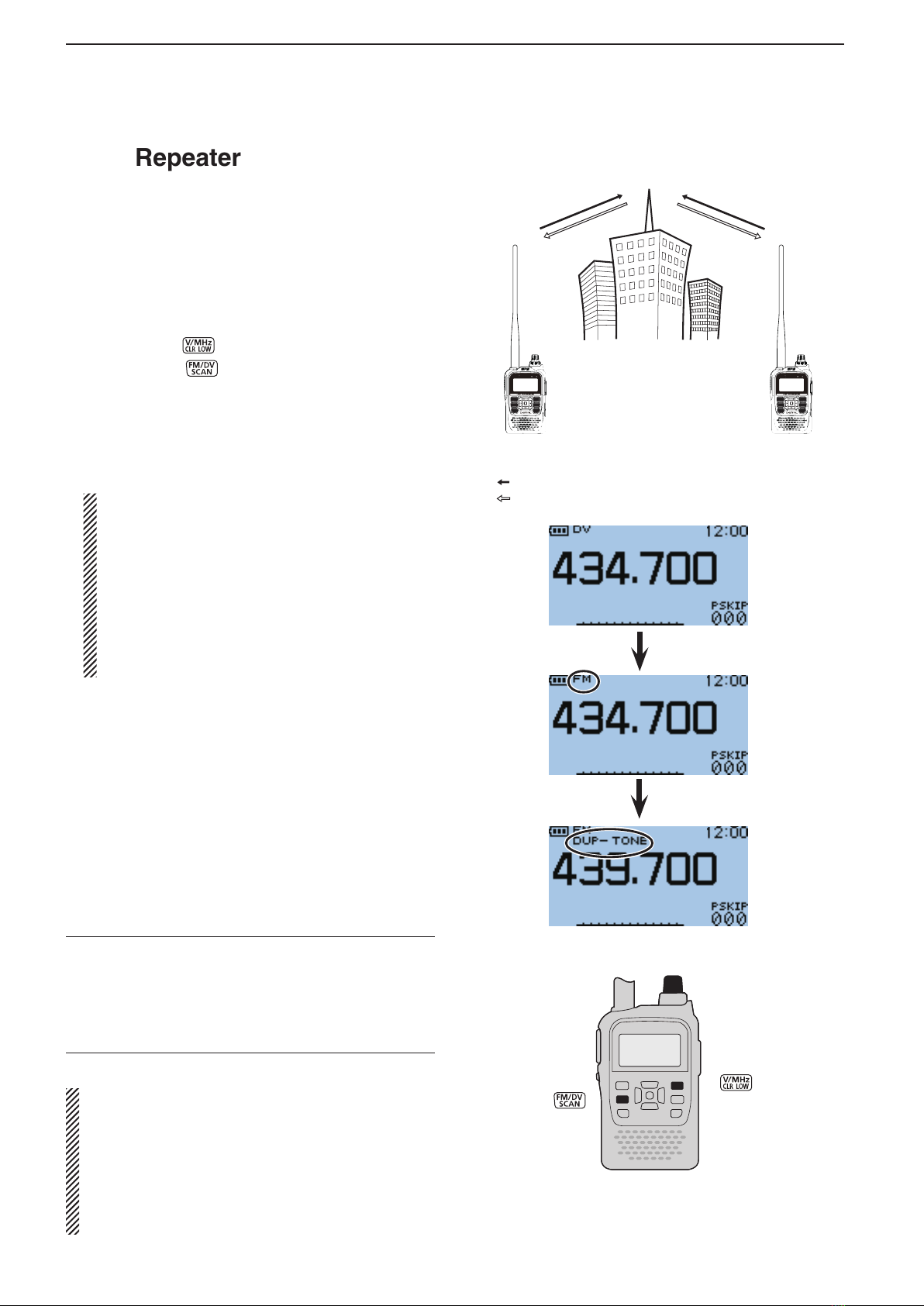
■FM Repeater operation
A repeater receives transmitted signals and retrans-
mits them on a different frequency. The transmit fre-
quency is shifted from the receive frequency by a pre-
set frequency offset.
In duplex operation, the transceiver’s frequency offset
is set to the same as that of the repeater. (p. 10-12)
DRepeater frequency setting
Push [V/MHz]qto select the VFO mode.
Push [FM/DV]wseveral times to select the FM
mode.
Rotate [DIAL] to set the receive frequency (repeatere
output frequency).
• The frequency changes according to the preset tuning
steps. See the page 23 on the printed manual for de-
tails.
Only USA and Korean versions have an Auto
Repeater function:
When the function is turned ON, steps rand t
are not necessary.*
(Default for USA version : ON (DUP))
(Default for Korean version : ON)
The Auto Repeater function can be turned OFF in
“Auto Repeater” on the MENU screen.
(MENU > Function > Auto Repeater)
See page 10-52 for details.
Set the duplex offset direction. (p. 1-5)r
• “DUP–” or “DUP+” appears.
Turn ON the repeater tone.t(See page 30 on the print-
ed manual.)
• “TONE” appears.
• The tone frequency can be set in the “REPEATER TONE”
screen. 88.5 Hz is set by default. (p. 10-12)
Communicate in the normal way.y
*For USA version, the Auto repeater function turns ON the
duplex operation only. To turn ON the repeater tone, you
should manually set as step t, or select “ON (DUP, TONE)”
in “Auto Repeater” on the MENU screen. (p. 10-52)
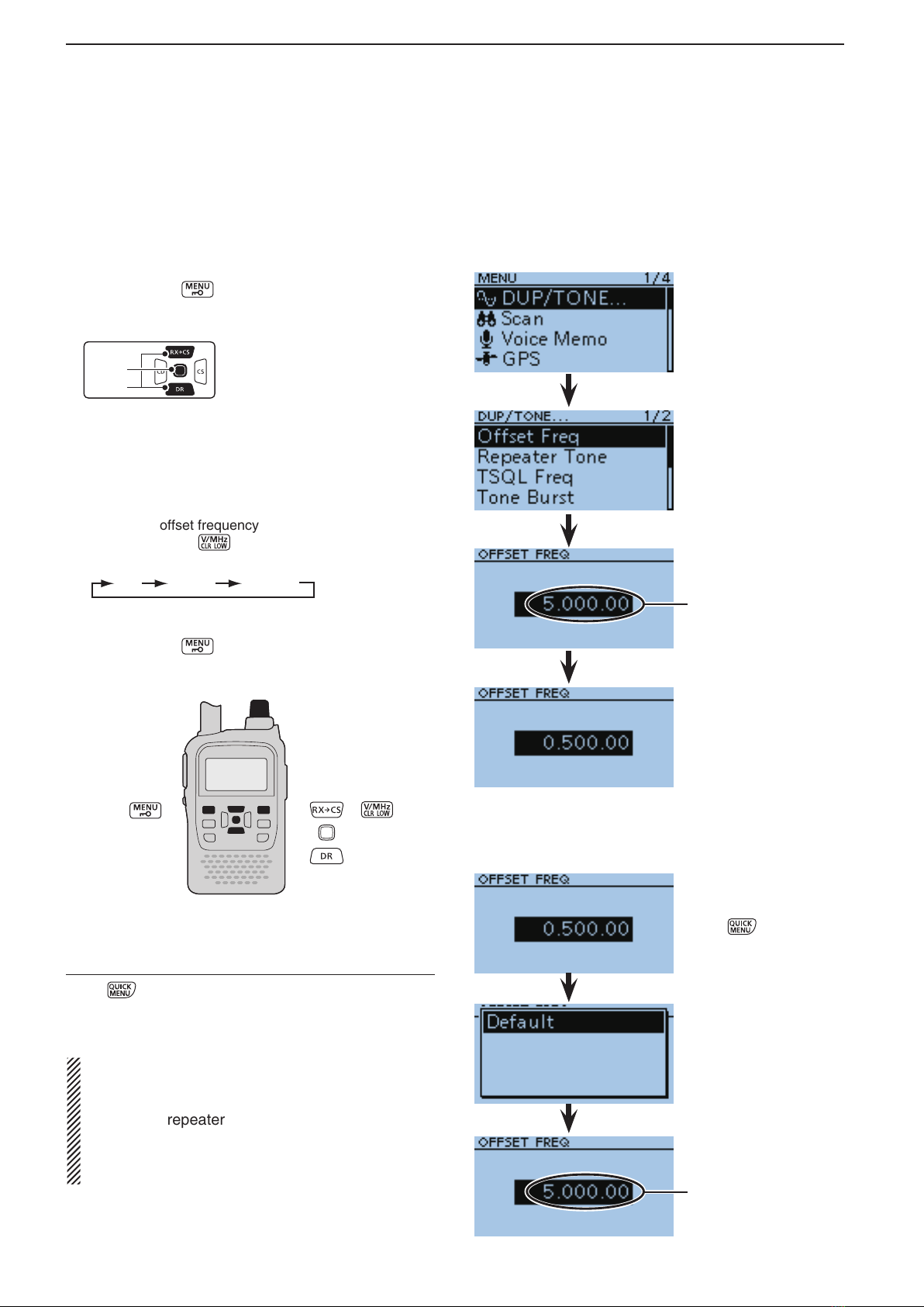
Information✓
The frequency offset (amount of shift) and the repeater
tone frequency are set in “Offset Freq” and “Repeater
Tone” of the MENU screen. (p. 10-12)
(MENU > DUP/TONE... > Repeater Tone)
(MENU > DUP/TONE... > Offset Freq)
Station A Station B
Repeater
439.700 MHz
434.700 MHz 434.700 MHz
439.700 MHz
Transmit frequency
Receive frequency
[DIAL]
NOTE:
• The Auto repeater function uses the preset repeat-
er tone frequency and frequency offset. Depending
on the frequency offset value, the off band indica-
tion, “OFF,” appears on the display when [PTT] is
pushed, and transmit is inhibited. (p. 1-5)
• See section 3 for details on accessing a D-STAR®
repeater.
Previous view

1
REPEATER AND DUPLEX OPERATIONS
1
2
3
4
5
6
7
8
9
10
11
12
13
14
15
16
17
18
19
20
21
1-3
DChecking the repeater input signal
You can check whether the other station’s transmit sig-
nal can be received directly or not, by listening on the
repeater input frequency.
Hold down [SQL] to listen on the repeater input fre-➥
quency.
• While monitoring, the TX/RX indicator lights green, and
an S/RF meter dot blinks.
• While monitoring, the displayed frequency automatically
changes to the transmit frequency (repeater input fre-
quency).
• When the other station’s signal can be directly received,
move to a non-repeater frequency and use simplex. (du-
plex OFF)
While monitoring
Hold
down
[SQL]
Blinks
Previous view

1REPEATER AND DUPLEX OPERATIONS
1-4
■Duplex operation
The Duplex operation shifts the transmit frequency
up or down from the receive frequency by an offset
amount.
DSetting the frequency offset
Push [MENU]q.
Push D-pad(w) to select the root item (“DUP/
TONE...”), and then push D-pad(Ent).
D-pad
(�)
(Ent)
Push D-pad(e) to select the “Offset Freq,” and then
push D-pad(Ent).
Rotate [DIAL] to set the frequency offset to betweenr
0.000.00 and 59.995.00 MHz, and then push D-
pad(Ent). (Setting example: 5.000.00)
• The selected tuning step in the VFO mode is used when
setting the offset frequency.
• Pushing [V/MHz] toggles the tuning digit, as shown
below.
TS* 1 MHz 10 MHz
*The frequency changes according to the preset tuning
steps. See page 23 on the printed manual for details.
Push [MENU]tto exit the [MENU] screen.
To reset to the default value.
Push in step ras described above, then push
D-pad(Ent) to reset to the default value.
NOTE:
• The frequency offset cannot be changed in the DR
mode.
• The Auto repeater function uses the preset fre-
quency offset. Depending on the frequency offset
value, the off band indication, “OFF,” appears on
the display when [PTT] is pushed. (p. 1-5)
The current frequency
offset
Rotate [DIAL], then
push D-pad(Ent).
Push
Push D-pad(Ent)
Default value
[DIAL]
Previous view

1
REPEATER AND DUPLEX OPERATIONS
1
2
3
4
5
6
7
8
9
10
11
12
13
14
15
16
17
18
19
20
21
1-5
DSetting the duplex direction
Push [V/MHz]qto select the VFO mode.
Push [FM/DV]wseveral times to select the FM
mode.
Rotate [DIAL] to set the operating frequency.e
Pushr.
Push D-pad(t) to select “DUP,” and then push D-
pad(Ent).
Push D-pad(y) to select “DUP–” (negative offset) or
“DUP+” (positive offset), and then push D-pad(Ent).
• OFF : For simplex operation (the receive and transmit
frequencies are the same).
• –DUP : The transmit frequency shifts down from the re-
ceive frequency by the offset amount.
• +DUP : The transmit frequency shifts up from the receive
frequency by the offset amount
■Off band indication
If the transmit frequency is out of the amateur band,
the off band indication, “OFF,” appears on the display
when [PTT] is pushed. Check the frequency offset (p.
1-4) or duplex direction (see above) in this case.
D-pad
(�)
(Ent)
Previous view

1REPEATER AND DUPLEX OPERATIONS
1-6
■Auto repeater function
When the operating frequency falls within the repeater
output frequency range, the Auto Repeater function
can automatically sets the repeater settings (duplex
ON/OFF, duplex direction, tone encoder ON/OFF).
The Auto repeater function uses the preset repeater
tone frequency and frequency offset. See page 10-2
for details of the setting.
DFrequency range and offset direction
• U.S.A. version
FREQUENCY RANGE SHIFT DIRECTION
442.000–444.995 MHz “DUP+” is set
447.000–449.995 MHz “DUP–” is set
• Korean version
FREQUENCY RANGE SHIFT DIRECTION
439.000–440.000 MHz “DUP–” is set
Push D-pad(q) to select the root item (“Function”),
and then push D-pad(Ent).
D-pad
(�)
(Ent)
Push D-pad(w) to select “Auto Repeater,” and then
push D-pad(Ent).
Rotate [DIAL] to select the Auto repeater setting.e
U.S.A. version:
• OFF : The Auto repeater function is OFF.
• ON (DUP) : Turns ON only the duplex operation.
(Default)
• ON (DUP, TONE) : Turns ON the duplex operation and
tone encoder
Korean version:
• OFF : The Auto repeater function is OFF.
• ON : Turns ON the duplex operation and
tone encoder. (Default)
Push [MENU]rto save and exit the [MENU]
screen.
NOTE:
When turned ON, the Auto repeater function uses
the preset repeater tone frequency and frequency
offset. See page 10-2 for details of the setting.
For the U.S.A. and Korean versions:
When turned ON, the Auto repeater function has pri-
ority over the manual duplex setting. If the transmit
frequency changes after setting, the Auto repeater
function may have changed the duplex setting.
[DIAL]
Previous view

1
REPEATER AND DUPLEX OPERATIONS
1
2
3
4
5
6
7
8
9
10
11
12
13
14
15
16
17
18
19
20
21
1-7
■1750 Hz tone
To access most European repeaters, the transceiver
must transmit a 1750 Hz tone. For such European re-
peaters, perform the following.
• This tone can also be used as a ‘Call signal.’
For only the ID-31E:
Push [PTT] briefly, then hold down [PTT] to transmit
a 1750 Hz tone burst signal.
Push D-pad(q) to select the root item (“DTMF/T-
CALL”), and then push D-pad(Ent).
D-pad
(�)
(Ent)
Push D-pad(w) to select “DTMF Memory,” and then
push D-pad(Ent).
Rotate [DIAL] to select “T-CALL,” and then pushe
D-pad(Ent) to set.
Push [MENU]rto exit the MENU screen.
Rotate [DIAL] to set the receive frequency (repeatert
output frequency).
Set the duplex offset direction. (p. 1-5)y
• “DUP–” or “DUP+” appears.
While holding down [PTT], push [SQL] to transmit au
1750 Hz tone signal.
• If “OFF BAND” appears, check the offset frequency or
shift direction. (pp. 1-4, 1-5)
• While transmitting, the displayed frequency automati-
cally changes to the transmit frequency (repeater input
frequency).
Hold down [SQL] to check whether the other sta-i
tion’s transmit signal can be received directly or not,
by listening on the repeater input frequency.
• While monitoring, the TX/RX indicator lights green, and
the S/RF meter dot blinks.
• While monitoring, the displayed frequency automatically
changes to the transmit frequency (repeater input fre-
quency).
• If you can hear the other station, you may want to change
to the Simplex mode and contact directly.
Push [PTT] to transmit.o
!0 Release [PTT] to receive.
[DIAL]
[PTT]
[SQL]
Previous view


1
2
3
4
5
6
7
8
9
10
11
12
13
14
15
16
17
18
19
20
21
2-1
Section 2
DR MODE <PREPARATION>
To begin the digital mode communication except for
the DR mode, you can use the VFO mode, Memory
mode and Call channel mode.
This manual describes focusing on the DR mode op-
eration which can be set up easily, and if you want to
use other mode, see the procedures as described to
the right.
For a Local area call or Gateway call:
Set the access repeater’s frequency. (p. 23 on theq
printed manual)
Set the frequency offset. (p. 1-4)w
Set the Duplex direction. (p. 1-5)e
Set the call signs. (p. 3-22)r
For a Simplex call:
Set the operating frequency.q
Set the call sign. (p. 3-21)w
To begin the digital mode communication except for the DR mode
IMPORTANT!
• The repeater list, described in this manual, may differ from your transceiver’s preset contents.
• Although the Japanese repeaters are used in the setting examples, the Japanese repeater node (port) letters
are different from other country’s.
Be sure to add a repeater node letter as the 8th digit in the call sign field after a repeater call sign, according to
the repeater frequency band, as shown below.
1200 MHz : A (B in Japan)
430 MHz : B (A in Japan)
144 MHz : C (no D-STAR®repeaters in Japan)
D-STAR■®INTRODUCTION ........................................... 2-2
About the DR (D-STAR■®Repeater) mode..................... 2-2
Communication Form■.................................................... 2-3
DR mode operation flow chart■....................................... 2-4
About Sections 3 and 4D.............................................. 2-4
“MY” (Your own call sign) programming■......................... 2-5

2DR MODE <PREPARATION>
2-2
■D-STAR®INTRODUCTION
• In the original D-STAR®(Digital Smart Technologies
for Amateur Radio) plan, JARL envisioned a system
of repeaters grouped together into Zones.
• The transceiver can be operated in the digital voice
mode, including low-speed data operation, for both
transmit and receive. It can also be connected to a
GPS receiver* to transmit and receive position data.
* Compatible with an RS-232 output/NMEA format/
4800bps/9600 bps
• The transceiver has a Time-Out Timer function for
digital repeater operation. The timer limits a con-
tinuous transmission to approximately 10 minutes.
Warning beeps will sound approximately 30 seconds
before time-out and then again immediately before
time-out.
■About the DR (D-STAR® Repeater) mode
The DR (D-STAR®Repeater) mode is one mode you
can use for D-STAR®repeater operation. In this mode,
you can select the preprogrammed repeater or fre-
quency in “FROM” (the access repeater or simplex),
and UR call sign in “TO” (destination), as shown to the
right.
NOTE: If the repeater, set to “FROM” (Access Re-
peater) has no Gateway call sign, you cannot make
a gateway call.
Destination
(Repeater/Station)
Access repeater
or Simplex
In the DR mode
Previous view

2
DR MODE <PREPARATION>
1
2
3
4
5
6
7
8
9
10
11
12
13
14
15
16
17
18
19
20
21
2-3
■Communication Form
In the DR mode, the transceiver has three communica-
tion forms as shown below.
• Local area call : To call a station through your local
area (access) repeater.
• Gateway call : To call through your local area (ac-
cess) repeater, repeater gateway,
and the internet to your destination
repeater or individual station’s last
used repeater, using call sign rout-
ing.
• Simplex call : To call a station through no repeater.
D局C局
レピータA
レピータD
430MHz
レピータC
10GHz
B局A局
レピータB
10GHz
430MHz
430MHz
430MHz
インターネット
回線
インターネット
回線
ゾーン
エリア
電波
インターネット
アンテナID-RP2L
D-
STAR
POWER
10BESE-T SERVICE1 SERVICE 2
ASSIST1 ASSIST2
ID-RP2C
RepeaterController
D-
ST
AR
SERVICE
POWER
ID-RP2D
RepeaterController
L/H
D-
ST
AR
SERVICETSERVICER
POWER
ID-RP2V
RepeaterController
ID-RP2C
ID-RP2V ID-RP2D
IC-2820G/DG
CQCQCQこちらJA3YUA
大阪平野430のレピータから
東京浜町430のレピータに
アクセスしております・・・
CQCQCQこちら
JA3YUA
大阪平野430の
レピータから
東京浜町430の
レピータにアクセス
しております・・・
大阪平野大阪平野
東京浜町東京浜町
D-STAR対応
無線機
■D-STARレピータの運用イメージ (大阪平野のレピータから 東京浜町のレピータに電波を出す場合)
アクセスレピータ
呼び出し先レピータ
インターネット網
INTERNET
NOTE:
• Programming the repeater list is required for DR mode operation. (pp. 4-21 to 4-28)
• You cannot make an Internet contact if your access repeater has no gateway.
• Before operating in the DV mode, be sure to check whether the repeater is busy, or not. If the repeater is busy,
wait until it is clear, or ask for a “break” using a method acceptable to your local procedures.
Access repeater
Local area call
Gateway call
Simplex call
Hamacho430
repeater
Hamacho area
Hirano area Sapporo area
Hirano430
repeater
Sapporo430
repeater
Previous view

2DR MODE <PREPARATION>
2-4
About Sections 3 and 4D
In sections 3 [DR mode <Basic>], and 4 [DR mode <Advance>], the following themes are described.
Convenient information and settings for using D-STAR®are described on each item.
Click the title as shown below to jump to the detail page.
■DR mode operation flow chart
Programming your “MY” call sign
STEP 2
PREPARATION
OPERATION
Registering your call sign
STEP 1
Selecting your “FROM” repeater
STEP 3
Selecting your “TO” repeater
STEP 4
Calling
STEP 5
To use a repeater gateway, you must register
your call sign with a gateway repeater, usually
one near your home location.
Ask your nearest repeater’s administrator for
details.
Your own call sign must be programmed for both
digital voice and low-speed data communica-
tions, including GPS transmission.
For Local area calls or Gateway calls, select
your access repeater.
For Simplex calls, select a preset frequency.
NOTE: If the repeater has no Gateway call
sign, you cannot make a gateway call.
Select the destination repeater or the destina-
tion call sign.
For a Local area call
For a Simplex call
For a Gateway call
(p. 3-2)
(p. 3-20)
(p. 3-3)
Push [PTT] to transmit.
Reply to a call
Other settings
Repeater list information
Repeater programming
Troubleshooting
Describes how to quickly and easily reply to a call. (p.
3-4)
Describes convenient functions (pp. 4-10 to 4-18)
(e.g. Auto reply function, Speech function, Low-speed
data communication, and so on)
Describes the preset repeater list information (p.
4-39)
Describes how to program new repeater information
(pp. 4-21 to 4-28)
Describes troubleshooting in using D-STAR® (See
’TROUBLESHOOTING’)
Previous view

2
DR MODE <PREPARATION>
1
2
3
4
5
6
7
8
9
10
11
12
13
14
15
16
17
18
19
20
21
2-5
Your own call sign must be programmed for both digital
voice and low-speed data communications (including
GPS transmission).
You can store up to 6 “MY” call signs, [MY1]–[MY6].
If necessary, enter a note of up to 4 characters, such
as the model of the transceiver, name, area indication,
and so on, after your call sign.
Example: Program “JA3YUA/ID31” into the call sign
memory channel [MY1].
Push [MENU]q.
Push D-pad(w) to select the root item (“My Sta-
tion”), and then push D-pad(Ent).
D-pad
(�)
(Ent)
Push D-pad(e) to select “My Call Sign,” and then
push D-pad(Ent).
Push D-pad(r) to select the call sign memory chan-
nel “1” ([MY1]).
Pusht.
Push D-pad(y) to select “Edit.”
Push D-pad(Ent) to enter the call sign programmingu
mode.
• A cursor appears and blinks.
Rotate [DIAL] to select the first digit. (Example: J)i
• A to Z, 0 to 9, / and (Space) can be selected.
• If you make a mistake, push [CLR] to delete the
selected character, symbol or number.
• Push D-pad(") to enter a space.
• Push D-pad() to move the cursor backward or forward.
Push D-pad(o") to move the cursor to second digit.
!0 Repeat steps iand oto enter your own call sign
of up to 8 characters, including spaces.
(For example: First, J, then A, then 3, then Y, then U,
then A)
To program a note (up to 4 characters, for operat-
ing radio type, area, and so on.), go to step !1,
otherwise go to step !3.
!1 Push D-pad(") several times to move the cursor to
the right of “/”.
!2 Repeat steps iand oto program the desired 4
character note.
(Example: ID31)
!3 Push D-pad(Ent) to set the programmed call sign
and note.
!4 Push D-pad(Ent) again to save and return to the MY
CALL SIGN screen.
• Two beeps sound.
!5 Push [MENU] to exit the MENU screen.
■“MY” (Your own call sign) programming
MY1
MY2
NOTE: If you have some D-STAR®transceiver, ask
your gateway repeater administrator for details.
Previous view


1
2
3
4
5
6
7
8
9
10
11
12
13
14
15
16
17
18
19
20
21
3-1
Section 3
DR MODE <BASIC>
Making a Local area call■.............................................................................. 3-2
D
Making a CQ call through your local area (access) repeater (Local Area CQ)
.. 3-2
Making a Gateway call■................................................................................. 3-3
Making a CQ call through a gateway repeater (Gateway CQ)D................. 3-3
One-touch reply after receiving a call■.......................................................... 3-4
“UR” (Destination call sign) programming using the RX History■.................. 3-5
“FROM” (Access repeater) setting■............................................................... 3-7
“DFROM” (Access repeater) setting using the preloaded repeater list ....... 3-8
“DFROM” (Access repeater) setting using the Repeater Search function .. 3-9
“DFROM” (Access repeater) setting using the TX History ........................ 3-11
“DFROM” (Access repeater) setting using the DR mode scan ................. 3-12
“TO” (Destination) setting■........................................................................... 3-13
“TO”D(Destination) setting using the “Your Call Sign”.............................. 3-14
“TO”D(Destination) setting using the RX History ..................................... 3-15
“DTO” (Destination) setting using the TX History...................................... 3-16
“DTO” (Destination) setting using the [Direct Input (UR)].......................... 3-17
“DTO” (Destination) setting using the [Direct Input (RPT)]........................ 3-18
About “UR?” and “RPT?” error messages■.................................................. 3-19
Shows “DUR?” .......................................................................................... 3-19
Shows “RPT?” or “RX”D............................................................................ 3-19
Shows “L”D................................................................................................ 3-19
Making a Simplex call■................................................................................ 3-20
Making a CQ call through no repeater (Simplex CQ)D............................. 3-20
For your reference■.................................................................................... 3-21
Making a Simplex call in the VFO modeD................................................. 3-21
Making a Local Area call or a Gateway call in the VFO modeD................ 3-22
IMPORTANT!
• The repeater list, described in this manual, may differ from your transceiver’s preset contents.
• Although the Japanese repeaters are used in the setting examples, the Japanese repeater node (port) letters
are different from other country’s.
Be sure to add a repeater node letter as the 8th digit in the call sign field after a repeater call sign, according to
the repeater frequency band, as shown below.
1200 MHz : A (B in Japan)
430 MHz : B (A in Japan)
144 MHz : C (no D-STAR®repeaters in Japan)

3DR MODE <BASIC>
3-2
■Making a Local area call
To call a station through your local area (access) repeater.
DMaking a CQ call through your local area
(access) repeater (Local Area CQ)
This section describes how to make a call through your
local area (access) repeater.
Example: Making a local CQ call by accessing the
“Hamacho430” repeater.
Hold downqfor 1 second.
• The DR mode is selected.
Push D-pad(w) to select “FROM” (Access repeater).
Rotate [DIAL] to select “Hamacho430.”e
Push D-pad(r) to select “TO” (Destination), and then
push D-pad(Ent).
Push D-pad(t) to select “Local CQ,” and then push
D-pad(Ent).
• “CQCQCQ” is displayed on “TO.”
While holding down [PTT], speak into the micro-y
phone at your normal voice level.
• The TX/RX indicator lights red.
• The S/RF meter shows the transmit output power level.
Release [PTT] to receive.u
JM1ZLK listening on
JP1YIU port A*...
‘JM1ZLK listening on
JP1YIU port A*...’
[DIAL]
[PTT]
Means this repeat-
er is programmed
as the 3rd of 635
repeaters in the
repeater list.
Shows the transmit
output power level
To maximize the readability of your signal, hold the
microphone 5 to 10 cm (2 to 4 inches) from your
mouth, then speak at a normal voice level.
Hamacho430
repeater
Hamacho area (Tokyo)
Settings are
complete
Caller:
JM1ZLK
Called
*Set the repeater node
to ‘B’ for 430 MHz band,
when you use in other
than Japan. See page
3-1 for details.
“CQCQCQ” select-
ed in “TO” scrolls.
Previous view

3
DR MODE <BASIC>
1
2
3
4
5
6
7
8
9
10
11
12
13
14
15
16
17
18
19
20
21
3-3
■Making a Gateway call
To call a station through your local area (access) repeater, gateway repeater, the internet and then to your destina-
tion repeater.
DMaking a CQ call through a gateway re-
peater (Gateway CQ)
This section describes how to make a CQ call through
a gateway repeater.
Example: Making a gateway CQ call to (Japan; Hi-
rano430) from the “Hamacho430” repeater.
Hold downqfor 1 second.
• The DR mode is selected.
Push D-pad(w) to select “FROM.”
Rotate [DIAL] to select “Hamacho430.”e
r
Push D-pad(
) to select “TO,” and then push D-pad(Ent).
Push D-pad(t) to select “Gateway CQ,” and then
push D-pad(Ent).
• The REPEATER GROUP screen is displayed.
Push D-pad(y) to select “11: Japan” (the repeater
group where your destination repeater is listed), and
then push D-pad(Ent).
Push D-pad(u) to select “Hirano430,” and then push
D-pad(Ent).
• “Hirano430” is displayed on “TO.”
While holding down [PTT], speak into the micro-i
phone at your normal voice level.
• The TX/RX indicator lights red.
• The S/RF meter shows the transmit output power level.
Release [PTT] to receive.o
JM1ZLK calling
through JP1YIU
Port A*...
‘JM1ZLK calling
through JP1YIU
Port A*...’
INTERNET
[DIAL]
[PTT]
To maximize the readability of your signal, hold the
microphone 5 to 10 cm (2 to 4 inches) from your
mouth, then speak at a normal voice level.
Hamacho430
repeater
Hirano430
repeater
Hamacho area
(Tokyo)
Hirano area (Osaka)
Caller:
JM1ZLK
Called
Means this repeat-
er is programmed
as the 3rd of the
635 repeaters on
the repeater list.
Shows the transmit
output power level Hirano430 call sign
scrolls with “/.”
Settings are
complete
Shows the high-
lighted name’s
call sign
Select “11: Japan”
where “Hirano430”
repeater is listed.
Shows it is a re-
peater for Gate-
way call
* Set the repeater node to ‘B’ for 430 MHz band, when you
use in other than Japan. See page 3-1 for details.
Previous view
Other manuals for D-STAR ID-31A; D-STAR ID-31E
3
This manual suits for next models
1
Table of contents
Other Icom Transceiver manuals

Icom
Icom IC-F61M User manual

Icom
Icom IC-F3230D User manual

Icom
Icom IC-718 Instruction manual

Icom
Icom IC-3210A User manual

Icom
Icom IC-746 User manual

Icom
Icom IC-F9020 SERIES User manual

Icom
Icom IC-V3500 Setup guide

Icom
Icom IC-7000 User manual

Icom
Icom IC-F3262DT User manual

Icom
Icom IC-F22SR User manual