PRESIDENT JOHNSON II USA 12/24 V User manual

Owner’s manual / Manual del usuario
Manuel d’utilisation / Manual do usuário
12/24 V

Votre PRESIDENT JOHNSON II USA 12/24 V en un coup d’œil Uma olhada no seu PRESIDENT JOHNSON II USA 12/24 V
Un vistazo a vuestro PRESIDENT JOHNSON II USA 12/24 VYour PRESIDENT JOHNSON II USA 12/24 V at a glance

3
SUMÁRIO
INSTALAÇÃO 46
UTILIZAÇÃO 48
CARACTERÍSTICAS TÉCNICAS 54
GUIA DE PROBLEMAS 55
COMO TRANSMITIR OU RECEBER UMA MENSAGEM 55
GLOSSÁRIO 55
GARANTIA 58
TABELAS DE FREQUÊNCIAS 59
SUMMARY
INSTALLATION 5
HOW TO USE YOUR CB 7
TECHNICAL CHARACTERISTICS 13
TROUBLE SHOOTING 13
HOW TO TRANSMIT OR RECEIVE A MESSAGE 14
GLOSSARY 14
WARRANTY 16
FREQUENCY TABLES 59
English
SOMMAIRE
INSTALLATION 32
UTILISATION 35
CARACTÉRISTIQUES TECHNIQUES 40
GUIDE DE DÉPANNAGE 41
COMMENT ÉMETTRE OU RECEVOIR UN MESSAGE 41
GLOSSAIRE 42
GARANTIE 44
TABLEAUX DES FRÉQUENCES 59
Français
Português
SUMARIO
INSTALACIÓN 18
UTILIZACIÓN 21
CARACTERÍSTICAS TÉCNICAS 26
GUÍA DE PROBLEMAS 27
COMO EMITIR O RECIBIR UN MENSAJE 27
LÉXICO 28
GARANTÍA 30
TABLAS DE FRECUENCIAS 59
Español

4
WARNING !
Before using, be careful never to transmit without first
havingconnectedtheantenna(connection“B”situated
on the back panel of the equipment) or without having
set the SWR (Standing Wave Ratio) ! Failure to do so may
result in destruction of the power amplifier, which is not
covered by the warranty.
The warranty of this transceiver is valid only in the country of purchase.
English
WARNING: This product can expose you to chemicals including Lead, which is known to the State of California to cause cancer and birth defects or other repro-
ductive harm. For more information go to www.P65Warnings.ca.gov.
AVERTISSEMENT : Ce produit peut vous exposer à des agents chimiques, y compris le plomb, identifiés par l’État de Californie comme pouvant causer le cancer et
des malformations congénitales ou autres effets nocifs sur la reproduction. Pour de plus amples informations, prière de consulter le site www.P65Warnings.ca.gov.

5
English
Welcome to the world of the new generation of CB ra-
dios. The new PRESIDENT range gives you access to top
performance CB equipment. With theuseofup-to-date
technology,which guarantees unprecedentedquality,
your PRESIDENT JOHNSON II USA 12/24 V is a new step
in personal communication and is the surest choice for
the most demanding of professional CB radio users. To
ensure that you make the most of all its capacities, we
adviseyou to readcarefully this manual before installing
and using your PRESIDENT JOHNSON II USA 12/24 V.
A) INSTALLATION
1) WHERE AND HOW TO MOUNT YOUR MOBILE CB RADIO
a) You should choose the most appropriate setting from a
simple and practical point of view.
b) Your CB radio should not interfere with the driver or the
passengers.
c) Remember to provide for the passing and protection of
different wires (e.g. power, antenna, accessory cabling)
so that they do not in any way interfere with the driving of
the vehicle.
d) Toinstallyour equipment,usethe cradle(1) andtheself-tap-
ping screws (2) provided (drilling diameter 3.2 mm). Take
care not to damage the vehicle’s electrical system while
drilling the dash board.
e) Do not forget to insert the rubber joints (3) between the
CB and its support as these have a shock-absorbing effect
which permits gentle orientation and tightening of the set.
f) Choose where to place the microphone support and
remember that the microphone cord must stretch to the
driver without interfering with the controls of the vehicle.
- N.B. : As the transceiver has a frontal microphone socket, it
can be set into the dash board. In this case, you will need
to add an external loud speaker to improve the sound
quality of communications (connector EXT.SP. situated on
thebackpanel:C).Askyourdealerforadviceonmounting
your CB radio.
MOUNTING DIAGRAM

6
2) ANTENNA INSTALLATION
a) Choosing your antenna
- For CB radios, the longer the antenna, the better its results.
Your dealer will be able to help you with your choice of
antenna.
b) Mobile antenna
- Must be fixed to the vehicle where there is a maximum of
metallic surface (ground plane), away from windscreen
mountings.
- If you already have a radio-telephone antenna installed,
the CB antenna should be higher than this.
- There are two types of antenna: pre-regulated which
should be used on a good ground plane (e.g. car roof or
lid of the boot), and adjustable which offer a much larger
range and can be used on a smaller ground plane (see §
ADJUSTMENT OF SWR page 7).
- Foran antenna whichmustbefixed by drilling,youwillneed
a good contact between the antenna and the ground
plane. To obtain this, you should lightly scratch the surface
where the screw and tightening star are to be placed.
- Be careful not to pinch or flatten the coaxial cable (as this
runs the risk of break down and/or short-circuiting).
- Connect the antenna (B).
c) Fixed antenna
- A fixed antenna should be installed in a clear a space as
possible. If it is fixed to a mast, it will perhaps be necessary
to stay it, according to the laws in force (you should seek
professional advice). All PRESIDENT antennas and acces-
sories are designed to give maximum efficiency to each
CB radio within the range.
3) POWER CONNECTION
Your PRESIDENTJOHNSONII USA12/24Visprotected against
aninversionofpolarities.However,beforeswitching iton,you
are advised to check all the connections. Your equipment
must be supplied with a continued current of 12 or 24 volts
(A). Today, most cars and lorries are negative earth. You
can check this by making sure that the negative terminal
of the battery is connected either to the engine block or
to the chassis. If this is not the case, you should consult your
dealer.
a) Check that the battery is of 12 or 24 volts.
b) Locate the positive and negative terminals of the battery
(+is red and -is black). Should it be necessary to lengthen
the power cable, you should use the same or a superior
type of cable.
OUTPUT
RADIUS
PATTERN
English

7
c) It is necessary to connect your CB to a permanent (+) and
(-). We advise you to connect the power cable directly to
thebattery(as the connection of the CBcabletothewiring
of the car-radio or other parts of the electrical circuit may,
in some cases, increase the likelihood of interference).
d) Connect the red wire (+) to the positive terminal of the
battery and the black (-) wire to the negative terminal of
the battery.
e) Connect the power cable to your CB radio.
WARNING: Never replace the original fuse (2 A) by one of
a different value.
4) BASICOPERATIONSTOBE CARRIEDOUTBEFOREUSING
YOUR SET FOR THE FIRST TIME (without transmitting
and without using the “push-to-talk” switch on the
microphone)
a) Connect the microphone
b) Check the antenna connections
c) Turn the set on by turning the volume knob (1) clockwise.
d) Turn the squelch SQ knob (2) to minimum (Mposition).
e) Adjust the volume to a comfortable level.
f) Go to channel 20 by using s, t, UP or DN keys (4, 5, 15,
14).
5) ADJUSTMENT OF SWR (Standing wave ratio)
WARNING: This must be carried out when you use your
CB radio for the first time (and whenever you re-position
your antenna). The adjustment must be carried out in an
obstacle-free area.
Adjustmentwith external SWR-meter(e.g.TOS-1PRESIDENT)
a) To connect the SWR meter :
- Connect the SWR meter between the CB radio and the
antenna as close as possible to the CB (use a maximum
of 15.75 inches (40 cm) cable, type President CA 2C).
b) To adjust the SWR meter:
- Set the CB to channel 20.
- Put the switch on the SWR-meter to position FWD (calibra-
tion).
- Press the “push-to-talk” switch on the microphone to trans-
mit.
- Bring the index needle to tby using the calibration key.
- Changetheswitchto positionREF(readingoftheSWRlevel).
The reading on the Meter should be as near as possible to
1. If this is not the case, re-adjust your antenna to obtain a
reading as close as possible to 1. (A SWR reading between
1 and 1.8 is acceptable).
- It will be necessary to re-calibrate the SWR meter after
each adjustment of the antenna.
WARNING: In order to avoid any losses and attenuations
in cables used for connection between the radio and its
accessories, PRESIDENT recommends to use a cable with
a length inferior to 118.11 inches (3 m).
Adjustment with internal SWR-meter
Shortpress•F/MEMkey (6) and s(4) or UP (14)keytoswitch
on (/off) the SWR function (see § •SWR page 8). SWR
level is displayed. When finished, switch off the function.
Your CB is now ready for use.
B) HOW TO USE YOUR CB
1) ON/OFF – VOLUME
a) To turn the set on, turn the VOL knob (1) clockwise.
b) To increase the sound level, turn the same knob further
clockwise.
English

8
2) ASC (Automatic Squelch Control) / SQUELCH
Suppresses undesirable background noises when there
is no communication. Squelch does not affect neither
sound nor transmission power, but allows a considerable
improvement in listening comfort.
a) ASC: AUTOMATIC SQUELCH CONTROL
Worldwide patent, a PRESIDENT exclusivity.
Turn the SQ knob (2) anti-clockwise into ASC position.
appears on the display. No repetitive manual adjustment
and a permanent improvement between the sensitivity
and the listening comfort when ASC is active. This function
can be disconnected by turning the switch clockwise. In
this case the squelch adjustment becomes manual again.
disappears from the display.
b) MANUAL SQUELCH
Turn the SQ knob clockwise to the exact point where all
background noise disappears. This adjustment should be
done with precision as, if set to maximum (fully clockwise),
only the strongest signals will be received.
3) DISPLAY
It shows all functions:
The BARGRAPH shows the reception level and the output
power level.
4) CHANNEL SELECTOR s~ TALKBACK LEVEL s~ •SWR
CHANNEL SELECTOR son unit (short press)
skey (4) allows increasing a channel. A beep sounds
each time the channel changes if the KEY BEEP function
is activated. (See KEY BEEP function page 12).
You can also use UP key (14) on the microphone.
TALKBACK LEVEL s(PTT + short press)
TALKBACK function lets you monitor yourself when trans-
mitting. Setting the level active automatically the function.
See page 13.
Press first PTT switch (12) and then skey (4) to increase
TALKBACK level from actual level to 9 (max.). The level is
displayed for 3 seconds if the PTT switch (12) is not released.
•SWR (•F/MEM + short press)
Short press •F/MEM key (6) and skey (4) to switch on/off
the SWR function. SWR level is displayed when function is
on.
5) CHANNELSELECTORt~TALKBACKLEVELt~•LOCAL
CHANNEL SELECTOR ton unit (short press)
tkey (5) allows decreasing a channel. A beep sounds
each time the channel changes if the KEY BEEP function
is activated. See KEY BEEP function page 12.
You can also use the DN key (15) on the microphone.
TALKBACK LEVEL t(PTT + short press)
TALKBACK function lets you monitor yourself when trans-
mitting. Setting the level active automatically the function.
See page 13.
English

9
Press first PTT switch (12) and then tkey (5) to decrease
TALKBACK level from actual level to 1 (min.). The level is
displayed for 3 seconds if the PTT switch (12) is not released.
•LOCAL (•F/MEM + short press)
Press •F/MEM (6) and tkey (5)to activate/deactivate.
“LOCAL” is displayed when the function is on.
This feature allows a better listening through close contact.
When your partner is close, active this function to avoid
distortion.
6) •F/MEM ~ DW ~ •COLOR
•F/MEM (short press)
Short press this key to enter in mode FUNCTION. blinks
when the function is on. automatically disappears after
10 seconds without pressing any key.
For memories, see § MEMORY page 12.
DW (long press)
Press and hold the DW key (6) for 1 second to activate/
deactivate the DUAL WATCH function. When function in
on, “DW” is displayed. This function lets you watch over
channel 9 or 19 and the channel you are using. The first
long press activates the DW function between channel 9
and the busy channel. A new press activates the function
between channel 19 and the busy channel. The number
of the selected channel, the memorized channel includ-
ed, and channel 9 or 19 are alternately displayed. “EMG”
is also displayed at the same time as channel 9 or 19. The
selected channel can be modified during the dual watch.
A new long press on DW key (6) disables the DW function.
•COLOR (•F/MEM + long press)
Press one time the •F/MEM key (6) and press and hold the
•COLORkey (6) for 1 second to alternate between 3 colors:
Green -> Blue -> Orange
7) 9/19 ~ HI-CUT ~ •M3
9/19 (short press)
Channels 9 and 19 are automatically selected by pressing
this key. A push activates channel 9, “EMG” is displayed. A
second push activates channel 19 “EMG” is displayed. A
newpushreturnstothepreviouschannel,“EMG”disappears.
HI-CUT (long press)
HI-CUT eliminates high frequency interferences. Has to be
usedinaccordancewiththereceptionconditions.“HI-CUT”
appears on the display when the HI-CUT filter is activated.
•M3
See § MEMORY page 12.
8) ANL/NB ~ SCAN ~ •M2
ANL/NB (short press)
ANL/Automatic Noise Limiter filter reduces back ground
noises and some reception interferences.
NB/Noise Blanker filter suppress an ignition noise in the
reception.
Short press ANL/NB key (8) key to alternate the 4 positions
switch: • ANL and NB off • ANL on / NB off • ANL off /NB
on • ANL and NB on.
When a filter is active, it name “ANL” or/and “NB”,is dis-
played on the LCD.
SCAN (long press)
CB MODE
Press and hold SCAN key (8) for 1 second to activate SCAN
function (for CB channels) in an increasing way. “SCAN”
English

10
is displayed. The scanning stops as soon as there is a busy
channel. The scanning automatically starts 3 seconds
after the end of the transmission and no key is activated
during 3 s. The scanning starts again in an increasing way
by pressing s(4) or UP (14) key, or in a decreasing way
by pressing t(5) or DN (15) key.
Whilescanning, press •F/MEMkey(6)to alternate between
All Channel Scan and Memory Channel Scan.
In Memory Scan Channel mode, channel 9, channel 19
and the memorised channels are scanned.
Press PTT switch (12), 9/19 key (7) , DW key (6) or long press
SCAN key (8) again to exit SCAN function.
WX MODE
Press and hold the SCAN key (8) for 1 second to activate
the SCAN function (for WEATHER channels) in an increas-
ing way. “SCAN” is displayed. The scanning stops as soon
as there is a busy channel. The scanning automatically
starts 3 seconds after the end of the transmission and no
key is activated during 3 s. The scanning starts again in
an increasing way by pressing s(4) or UP (14) key, or in a
decreasing way by pressing t(5) or DN (15) key.
Note: If the ALERT function is activated, the SIREN tone
sounds (see § ALERT below) when a tone is detected in the
selected WEATHER channel only. Use first SCAN function in
WX mode to detect tones in all the WEATHER channels.
A new long press on SCAN disables the SCAN function.
•M2
See § MEMORY page 12.
9) WX ~ ALERT ~ •M1
WX (WEATHER MODE) (short press)
CB functions are not allowed in WX mode. If user presses
a not allowed key and KEY BEEP function is activated, the
radio sounds error tone.
Press WX key (9) in order to activate the WX mode. “WX”
appears on the display. A new short press on WX key (9)
disables the WX mode “WX” disappears.
The WX mode allows to hear weather information. When
the mode is activated, use s/tkey (4/5) or UP/DN key
(14/15) on the microphone to move through the 7 weather
channels to find the active channel in your local area.
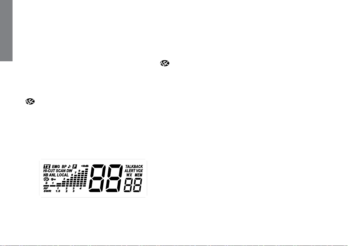
The display shows the selected weather channel and if the
unit receives a signal, “WX” and “ALERT” icons blink.
ALERT (long press)
The SIREN tone only sounds in CB and PA mode. It does not
sound in WX mode.
Press and hold the ALERT key (9) for 1 second to activate/
deactivatethe ALERT function.When the function is on and
a tone is detected at the selected weather channel, then
the unit sounds SIREN tone. “ALERT” and the “WX channel”
blink on the display. The unit cancel CB or PA mode and
go to WX mode.
During a SIREN tone sound, press any key to stop the sound,
“ALERT” and the “WX channel” stop blinking on the display.
Note: The SIREN tone sounds when ALERT is detected in the
selected WEATHER channel only. Use first SCAN function in
WX mode (see § WX MODE above) to detect tones in all
the WEATHER channels.
•M1
See § MEMORY page 12.
10) CB/PA ~ LOCK ~ •VOX ~ •VOX SET
CB/PA (short press)
Short press CB/PA key (10) to alternate between CB and
PA mode.
English

11
PA MODE
An external loud speaker can be connected to the unit by
the PA jack plug situated on the back panel PA.SP. (D). The
PA volume is regulated by VOL knob (1). “PA” is displayed.
ROGER,SCAN,MEM, VOX are not allowed in PA mode. Ifthe
user set on PA mode while SCAN function, instant channel
9/19 mode or WX mode, these are canceled.
The CB message received will be directed towards the PA
speaker and be amplified.
The message transmitted into the microphone will be di-
rected towards the PA speaker and be amplified. “PAon”
is displayed, Meter numbers indicate signal level.
LOCK (long press)
Allows to lock all the keys on the front panel. if the KEY BEEP
function is on, an error beep sounds when a key is used.
A long press on LOCK key (10) activates/deactivates the
LOCKfunction. appears onthedisplay when thefunction
is activated.
Transmission (microphone or vox) and reception remain
active.
•VOX (•F/MEM + short press)
The VOX function allows transmitting by speaking into the
original microphone (or in the optional vox microphone)
without pressing the PTT switch (12). The use of an optional
vox microphone connected to the rear panel of the trans-
ceiver (E) disables the original microphone.
Press one time •F/MEM key (6) and short press •VOX key
(10) in order to activate the VOX function. “VOX” appears
on the display. Repeat the key combination to disable the
function. “VOX” disappears.
•VOX SET (•F/MEM + long press)
Pressonetimethe •F/MEMkey(6)and pressduring1second
•VOXkey(10)inordertoactivatethefunctionVOXSETTING.
Three adjustments are possible: Sensitivity / Anti-vox level
/ Vox delay time . Press shortly •VOX (10) in order to go
to the following adjustment (looping , , ).
The display shows the type of adjustment followed by its
level.
- Sensitivity : allows the adjustment of the microphone
(original one or optional vox) for an optimum transmission
quality. Adjustable level from 1 (high level) to 9 (low level)
bypressings/t(4/5)orUP/DN(14/15) keys . corresponds
to the Sensitivity Level.
- Anti-Vox : allows disabling the transmission generated by
the surrounding noise. The level is adjustable from 0 (Off) to
9 (low level) by pressing s/t(4/5) or UP/DN (14/15) keys.
corresponds to Anti-vox Level.
- Delay time : allows avoiding the sudden cut of the trans-
mission by adding a delay at the end of speaking. The
level is adjustable from 1 (short delay) to 9 (long delay) by
pressing s/t(4/5) or UP/DN (14/15) keys. corresponds
to Delay Time.
Once the adjustments are done, short press •F/MEM key
(6) key in order to quit the Vox Adjustment mode.
When VOX SETTING is done the VOX function is automati-
cally ON. “VOX” appears on the display.
11) 6 PIN MICROPHONE PLUG
Theplug is located onthefrontpanel of thetransceiverand
makes the setting of the equipment into the dashboard
easier.
See cabling diagram page 60.
English

12
12) PTT
Transmissionkey,presstotransmita message, isdisplayed
and release to listen to an incoming communication.
14) CHANNEL SELECTOR UP on microphone
UP key (14) allows increasing a channel. A beep sounds
each time the channel changes if the KEY BEEP function
is activated (see KEY BEEP function below).
You can also use skey (4) on the unit.
15) CHANNEL SELECTOR DN on microphone
DN key (15) allows decreasing a channel. A beep sounds
each time the channel changes if the KEY BEEP function
is activated (see KEY BEEP function below).
You can also use tkey (5) on the unit.
ROGER BEEP
Start the unit while pressing s(4) or UP (14) key to activate
theROGERBEEPfunction.A beepsoundsifKEYBEEP function
is on.
The icon “ ” appears on the display when the function is
active. The Roger Beep sounds when the PTT switch (12) of
the microphone is released in order to let your correspond-
ent speak. Historically as CB is a “simplex” communication
mode, it is not possible to speak and to listen at the same
time (as it is the case with a telephone). Once someone
had finished talking, he said “Roger” in order to prevent his
correspondent that it was his turn to talk. The word “Roger”
has been replaced by a significant beep. There comes
“Roger beep” from.
Note: the Roger beep also sounds in the loudspeaker if the
KEY BEEP function is active. If the KEY BEEP function is not
active, only the correspondent can hear the Roger Beep.
In PA mode the function is not allowed.
KEY BEEP
Beep on changing the channel, keys etc...
Start the unit while pressing t(5) or DN (15) key to activate
the KEY BEEP function. A beep sounds. “BP” is displayed.
Start again the unit while pressing t(5) or DN (15) key to
deactivate the KEY BEEP function. “BP” disappears.
MEMORY
This CB radio allows to memorize 3 channels with following
parameters: ANL (on/off), NB (on/off), HI-CUT (on/off).
To recall amemory: (short press)
- Short press •F/MEM key (6). If the KEY BEEP function is acti-
vated a beep sounds.
- Short press •M1 (9), •M2 (8) or •M3 (7) key to recall the
selected memory.
“MEM” and the number of the memory (1, 2or 3) appears
on the display
To memorize: (long press)
- Select the channel and parameters to be memorized.
- Short press •F/MEM key (6). If the KEY BEEP function is acti-
vated a beep sounds.
- Press •M1 (9), •M2 (8) or •M3 (7) key during 1 second to
store the selected channel into memory. “MEM” appears.
- If the KEY BEEP function is activated a long beep confirms
the saving.
To delete amemory:
- Switch off the transceiver.
- Keep the memory key •M1 (9), •M2 (8) or •M3 (7) pressed
and switch on the transceiver.
- The selected memory is deleted. “MEM” disappears.
English

13
TALKBACK FUNCTION (PTT + •F/MEM )
Press first PTT switch (12) and then •F/MEM key (6) to acti-
vate/deactivate TALKBACK function. When the function is
on, “TALKBACK” is displayed.
TOT (Time Out Timer)
If the transmission (using the PTT (12) key or VOX) is more
than 5 minutes, CHANNEL and starts blinking, the trans-
mission ends.
The time-out tone will sound until the PTT key is released.
A) DC-POWER TERMINAL (13,8 V / 27,6 V)
B) ANTENNA CONNECTOR (SO-239)
C) EXTERNAL SPEAKER JACK (8 Ω, Ø 3,5 mm)
D) PA SPEAKER JACK (
8 Ω, Ø 3,5 mm)
E) JACK FOR OPTIONAL VOX MIKE (Ø 2.5 mm)
C) TECHNICAL CHARACTERISTICS
1) GENERAL
- Channels : 40
- Modulation modes : AM
- Frequency ranges : from 26.965 MHz to 27.405 MHz
- Weather channels : from 162.400 MHz to 162.550 MHz
- Antenna impedance : 50 ohms
- Power supply : 13.8 V / 27.6 V
- Dimensions (W x D x H) : 6.69 x 5.91 x 2.05 inches
170 x 150 x 52 mm
- Weight : 2.20 lbs / 1 kg
- Accessories supplied : Ultra light electret microphone with
support, mounting cradle, screws
2) TRANSMISSION
- Frequency allowance : +/- 200 Hz
- Carrier power : 4 W (constant)
- Transmission interference : inferior to -60 dBc
- Audio response : 300 Hz to 3 KHz
- Emitted power in the adj.
channel : inferior to 20 µW
- Microphone sensitivity : 3 mV
- Drain : 2 A (with modulation)
- Modulated signal distortion : 1.8 %
3) RECEPTION
- Maxi. sensitivity at
10 dB (S+N)/N : 0.6 µV - 111 dBm
- Frequency response : 300 Hz to 3 kHz
- Adjacent channel selectivity : > 60 dB
- Maximum audio power : 2 W
- Squelch sensitivity : minimum 0.2 µV - 120 dBm
maximum 1 mV - 47 dBm
- Frequency image rejection
rate : 60 dB
- Intermediate frequency
rejection rate : 70 dB
- Drain : 300mA nominal/1000 mAmaximum
D) TROUBLE SHOOTING
1) YOUR CB RADIO WILL NOT TRANSMIT OR YOUR
TRANSMISSION IS OF POOR QUALITY
- Check that the antenna is correctly connected and that
the SWR is properly adjusted.
- Check that the microphone is properly plugged in.
English

14
2) YOUR CB RADIO WILL NOT RECEIVE OR RECEPTION IS
POOR
- Check that LOCAL function is off.
- Check that the squelch level is properly adjusted.
- Check that the volume is set to a comfortable listening
level.
- Check that the antenna is correctly connected and that
the SWR is properly adjusted.
3) YOUR CB WILL NOT LIGHT UP
- Check the power supply.
- Check the connection wiring.
- Check the fuse.
E) HOW TO TRANSMIT OR RECEIVE A
MESSAGE
Now that you have read the manual, make sure that your
CB Radio is ready for use (i.e. check that your antenna is
connected).
Pressthe“push-to-talk”switchandannounceyourmessage
“Attention stations, transmission testing” which will allow
you to check the clearness and the power of your signal.
Release the switch and wait for a reply. You should receive
a reply like, “Strong and clear”.
If you use a calling channel (19) and you have established
communication with someone, it is common practice to
choose another available channel so as not to block the
calling channel.
F) GLOSSARY
BelowyouwillfindsomeofthemostfrequentlyusedCBradio
expressions. Remember this is meant for fun and that you
are by no means obliged to use them. In an emergency,
you should be as clear as possible.
INTERNATIONAL PHONETIC ALPHABET
AAlpha HHotel OOscar VVictor
BBravo IIndia PPapa WWhiskey
CCharlie JJuliett QQuebec X-ray
DDelta KKilo RRomeo YYankee
EEcho LLima SSierra ZZulu
FFoxtrott MMike TTango
GGolf NNovember UUniform
TECHNICAL VOCABULARY
AM : Amplitude Modulation
CB : Citizen’s Band
CH : Channel
CW : Continuous Wave
DX : Long Distance Liaison
DW : Dual Watch
FM : Frequency Modulation
GMT : Greenwich Meantime
HF : High Frequency
LF : Low Frequency
LSB : Lower Side Band
RX : Receiver
SSB : Single Side Band
SWR : Standing Wave Ratio
SWL : Short Wave Listening
SW : Short Wave
TX : CB Transceiver
English

15
UHF : Ultra High Frequency
USB : Upper Side Band
VHF : Very High Frequency
CB LANGUAGE
Advertising : Flashing lights of police car
Back off : Slow down
Basement : Channel 1
Base station : A CB set in fixed location
Bear : Policeman
Bear bite : Speeding fine
Bear cage : Police station
Big slab : Motorway
Big 10-4 : Absolutely
Bleeding : Signal from an adjacent channel
interfering with the
transmission
Blocking the channel : Pressingthe PTTswitchwithout talking
Blue boys : Police
Break : Used to ask permission to join a
conversation
Breaker : A CBer wishing to join a channel
Clean and green : Clear of police
Cleaner channel : Channel with less interference
Coming in loud and
proud : Good reception
Doughnut : Tyre
Down and gone : Turning CB off
Down one : Go to a lower channel
Do you copy? : Understand?
DX : Long distance
Eighty eights : Love and kisses
Eye ball : CBers meeting together
Good buddy : Fellow CBer
Hammer : Accelerator
Handle : CBer’s nickname
Harvey wall banger : Dangerous driver
How am I hitting you? : How are you receiving me?
Keying the mike : Pressing thePTT switchwithouttalking
Kojac with a kodak : Police radar
Land line : Telephone
Lunch box : CB set
Man with a gun : Police radar
Mayday : SOS
Meat wagon : Ambulance
Midnight shopper : Thief
Modulation : Conversation
Negative copy : No reply
Over your shoulder : Right behind you
Part your hair : Behave yourself - police ahead
Pull your hammer back : Slow down
Rat race : Congested traffic
Rubberbander : New CBer
Sail boat fuel : Wind
Smokey dozing : Parked police car
Smokey with a camera : Police radar
Spaghetti bowl : Interchange
Stinger : Antenna
Turkey : Dumb CBer
Up one : Go up one channel
Wall to wall : All over/everywhere
What am I putting to
you? : Please give me an S-meter reading
English

16
• Transceivers which have been modified. The warranty application is excluded
in case of modification or poor maintenance done by a third party not approved
by PRESIDENT ELECTRONICS.
If you note a malfunction:
• Check the power supply of your device and the quality of the fuse.
• Check that the antenna, the microphone are correctly connected.
• Check that the squelch level is properly adjusted; the programmed configuration
is the correct one.
• In the event of a real malfunction, please contact your dealer first. He will decide
what action should be taken.
In case of an intervention not covered by warranty, an estimate will be established
before any repair.
Thank you for your confidence in the PRESIDENT quality and experience. We
recommend that you read this manual carefully so that you are completely satisfied
with your purchase.
Technical Manager
and
Quality Manager
This device is guaranteed 2 years parts and labour in its country of purchase
against any manufacturing defects validated by our technical department. PRES-
IDENTAfter Sales Service department reserves the right not to apply the warranty
in the event a breakdown is caused by an antenna other than those distributed by
PRESIDENT. An extension of 3 years warranty is proposed systematically for the
simultaneous purchase of a device and a PRESIDENT antenna, bringing the total
duration of the warranty to 5 years. In order to be valid, the warranty registration
must be completed and submitted within a period of 30 days after the purchase
date to PRESIDENT ELECTRONICS online at
www.president-electronics.
us/warranty-registration
. You can also access this warranty registration page
by using your smartphone to read (application must be available) the QR code.
You will receive a confirmation email if the registration is successfully completed.
Please keep a copy of this email for your records.
Any repair under warranty will be without charge and the return delivery costs will
be borne by PRESIDENT. A proof of purchase sales receipt must be included with
the device to be repaired. The dates listed on the warranty registration and proof
of purchase must match. In case the device is not under warranty, the repair and
return of the device will be charged.
No spare parts will be sent nor exchanged by PRESIDENT under warranty. Do
not proceed with the installation of the device without reading the user manual.
The warranty is only valid in the country of purchase.
Exclusions (not covered by Warranty):
• Damages caused by accident, shock or inadequate packaging.
• Power transistors, microphones, lights, fuses and the disrespect of the instal-
lation and use of specifications (including but not limited to antenna used with
too high power, final output power transistors (SWR), inversion of polarities, bad
connections, over voltage…).
• The warranty cannot be extended due to the non-availability of the device while
it is being serviced at PRESIDENT After Sales Service department, nor by a
change of one or more components or spare parts.
GENERAL WARRANTY CONDITIONS
English
Warranty Registration

17
Español
¡ ATENCIÓN !
Antes de la utilización tengan cuidado de nunca emitir
sin haber previamente conectado la antena (conector
“B”situado en la parte trasera de su equipo), ajustada la
ROE (Relación de Ondas Estacionarias)! Sino, se expone
a dañar el amplificador de potencia, no cubierto por
la garantía.
La garantía de este artículo sólo es válida en el país de compra.
WARNING: This product can expose you to chemicals including Lead, which is known to the State of California to cause cancer and birth defects or other repro-
ductive harm. For more information go to www.P65Warnings.ca.gov.
AVERTISSEMENT : Ce produit peut vous exposer à des agents chimiques, y compris le plomb, identifiés par l’État de Californie comme pouvant causer le cancer et
des malformations congénitales ou autres effets nocifs sur la reproduction. Pour de plus amples informations, prière de consulter le site www.P65Warnings.ca.gov.

18
Español
Bienvenido al mundo de los emisores-receptores CB de
última generación. Esta nueva gama de estaciones le
permite acceder a la comunicación electrónica más
competitiva. Gracias a la utilización de tecnología
punta que garantiza una calidad sin precedentes, su
PRESIDENTJOHNSON II USA12/24 V representaun nuevo
hito en la facilidad de uso y la solución por excelencia
para el pro más exigente de CB. Para sacar el máximo
partido de todas sus posibilidades, le aconsejamos leer
atentamenteestasinstruccionesdeusoantesde instalar
y utilizar su CB PRESIDENT JOHNSON II USA 12/24 V.
A) INSTALACIÓN
1) ELEGIR EL EMPLAZAMIENTO Y MONTAJE DEL PUESTO
MÓVIL
a) Escoja el emplazamiento más apropiado para una utiliza-
ción simple y práctica de su estación móvil.
b) Procure que no moleste ni al conductor ni a los pasajeros
del vehículo.
c) Prevea el paso y la protección de los diferentes cables,
(alimentación, antena, accesorios) con el fin de que en
ningún caso perturben la conducción del vehículo.
d) Utilice para el montaje el soporte (1) entregado con el
aparato, fíjelo sólidamente con ayuda de los tornillos au-
to-roscantes (2) proporcionados (diámetro de agujero de
3,2 mm). Tenga cuidado de no dañar el sistema eléctrico
del vehículo en el momento del taladro del salpicadero.
e) En el momento del montaje, no se olvide de insertar las
arandelas de caucho (3) entre la estación y su soporte.
Éstas tienen, en efecto, un papel “amortiguador” y per-
miten una orientación y presión suaves de la estación.
f) Escoja un emplazamiento para el soporte del micro y
prevea el paso de su cable.
- NOTA: Su estación móvil que posee una toma de micro en
la parte anterior puede ser empotrada en el cuadro de
mandos. En ese caso, se recomienda añadirle un altavoz
externo para una mejor escucha de las comunicaciones
(conector EXT.SP situado en la cara posterior del aparato:
C). Infórmese con su vendedor más próximo para el mon-
taje en su aparato.
ESQUEMA GENERAL
DE MONTAJE

19
2) INSTALACIÓN DE LA ANTENA
a) Elección de la antena
- En CB, cuanto más grande es una antena, mejor es su
rendimiento. Su Centro de Asesoramiento sabrá orientarle
en su elección.
b) Antena móvil
- Hay que instalarla en un lugar del vehículo donde haya
un máximo de superficie metálica (plano de masa), ale-
jándose de los montantes del parabrisas y de la luneta
trasera.
- En caso de que se haya instalado una antena de radio-te-
léfono, la antena CB debe estar por encima de ésta.
- Existen2tiposdeantenas:laspreajustadasy las regulables.
- Las preajustadas se utilizan preferentemente con un buen
plano de masa (en el techo o en el maletero).
- Las regulables ofrecen un campo de uso mucho más an-
cho y permiten sacar partido de planos de masa menos
importantes (véase § 5 AJUSTE DE LA ROE).
- Para una antena de fijación por taladro, es necesario
tener un contacto excelente entre la antena y el plano
de masa; para ello, rasque ligeramente la chapa al nivel
del tornillo y de la estrella de presión.
- En el momento del paso del cable coaxial, tenga cuidado
de no pellizcarlo ni aplastarlo (riesgo de rotura o cortocir-
cuito).
- Conecte la
antena (B).
c) Antena fija
- Procure abrirla al máximo. En caso de fijación sobre un
poste, habrá que sostenerla eventualmente conforme a
las normas vigentes (infórmese con un profesional). Las
antenas y los accesorios PRESIDENT han sido especialmen-
te concebidos para un rendimiento óptimo de todos los
aparatos de la gama.
3) CONEXIÓN DEL ALIMENTADOR
Su PRESIDENT JOHNSON II USA 12/24 V está provista de una
protección contra las inversiones de polaridad.
Vuestra emisora debe estar alimentada por una fuente de
corriente continua de 12 o 24 voltios (A). En este momento,
la mayor parte de los coches y camiones funcionan con
unatomadetierranegativa,sepuedeasegurarverificando
que el terminal (-) de la batería esté bien conectado al
bloque del motor o bastidor. En el caso contrario, consulte
con su suministrador.
Todas las operaciones de conexión siguientes, deben
efectuarse con el cable de alimentación no conectado
a la emisora:
a) Asegúrense que el alimentador sea de 12 o 24 Voltios.
b) Identifique los polos (+) y (-) de la batería (+= rojo, -=
negro). En el caso que sea necesario alargar el cable de
alimentación utilice un cable de sección equivalente o
superior.
LÓBULO DE
RADIACIÓN
Español

20
c) Es necesario conectar sobre un (+) y (-) permanentes.
Les aconsejamos enchufar directamente el cable de
alimentación en la batería (el enchufe sobre el cable del
auto-radio o sobre otras partes del circuito electrónico
podrán en ciertos casos favorecer la recepción de las
señales parásitas).
d) Conecten el hilo rojo (+) al borne positivo de la batería y
el hilo negro (-) al borne negativo de la batería.
e) Conectar el cable de alimentación a la emisora.
ATENCIÓN: ¡No reemplace jamás el fusible de origen (2 A)
por un modelo de un valor diferente!
4) OPERACIONESDEBASEQUE HAYQUEEFECTUARANTES
DE LA PRIMERA UTILIZACIÓN, SIN PASAR POR EMISIÓN
(sin apretar la palanca del micro)
a) Conecte el micro,
b) Verifique la conexión de la antena,
c) Puesta en marcha del aparato: gire el botón del volumen
VOL (1) en el sentido de las agujas del reloj hasta oír un
“clic”.
d) Gire el botón del squelch SQ (2) al mínimo (posición M).
e) Ajuste el botón del volumen (1) a un nivel conveniente.
f) Dirija la estación al canal 20 con ayuda de las teclas s/t
(4/5) o UP/DN (14/15) del micrófono.
5) AJUSTE DE LA ROE (Relación de Ondas Estacionarias)
ATENCIÓN:Esta operacióndebeefectuarsenecesariamen-
te en el momento de la primera utilización del aparato o
en el momento de un cambio de antena. Este ajuste debe
se realizar en un lugar abierto, al aire libre.
Ajustes con el medidor de ROE externo (tipo TOS-1
PRESIDENT):
a) Empalme del medidor de ROE:
- Conecte el medidor de ROE entre la estación y la antena,
lo más cerca posible de la estación (utilice para ello un
cable de 40 cm máximo tipo CA-2C PRESIDENT).
b) Ajuste de la ROE:
- Posicione la estación hacia el canal 20,
- Sitúe el conmutador del medidor de ROE en posición FWD
(calibración),
- Apriete la palanca del micro para pasar a emisión,
- Dirija la aguja al índice ▼con ayuda del botón de cali-
bración,
- Ponga el conmutador en posición REF (lectura del valor de la
ROE). El valor leído en el indicador debe estar muy cerca de 1.
En caso contrario, reajuste su antena hasta obtener un valor lo
más cerca posible a 1 (puede aceptarse un valor de la ROE
comprendido entre 1 y 1,8),
- Es necesario recalibrar el medidor de ROE entre cada
operación de ajuste de la antena.
Observación: Con el fin de evitar las pérdidas y las ate-
nuaciones en los cables de conexión entre la radio y sus
accesorios, PRESIDENT recomienda una longitud de cable
inferior a 3m.
Ajustes con el medidor de ROE interno
Presione la tecla •F/MEM (6) y la tecla s(4) o UP (14) del
micrófono para activar/desactivarla función SWR (ver
§ •SWR página 21). El nivel de la ROE aparece en la
pantalla. Cuando termine, desactive la función SWR.
Ahora, su estación está preparada para funcionar.
Español
This manual suits for next models
1
Table of contents
Languages:
Other PRESIDENT Car Receiver manuals