Primex Verge MDE P2100 User manual

Fit everything. Together.
FOR MORE INFORMATION CONTACT:
T
1.604.881.7875 F1.604.881.7835
www.primex.com
STEP 1
STEP 3
Install horizontal joist and gang box
To ensure a comfortable working height it is recommended that the
top of the gang box be installed 36” from the ground using a level.
Note: Leave at least a 2” buffer zone around base to keep clear from
perpendicular walls.
Remove knock outs
Prior to installation, remove the knockouts for the conduit and
electrical box using a flush cutter tool.
STEP 2
STEP 4
Connect power and install electrical outlet faceplate
At this stage, connect conduit for outgoing and incoming services and
secure with Primex conduit adapters.
Install base over top of the gang box using No. 8 flat
head screws
Install single screw in corner flange, level, then secure with
additional screws.
The Primex Verge WiFi transparent Media Distribution
Enclosures bring fiber inside and forms the center piece of
the connected home. Its flexible design provides a convenient,
lockable and centralized location for easy installation and
distribution of multi-play and smart home services within
residential and commercial premises.
VERGE MDE INSTALLATION (P3000 SHOWN)
PRIMEX
MDE Installation Instructions Verge MDE
P2100, P3000, P4200, P6300
• DO NOT stretch enclosure walls or lid won’t seat properly.
• DO NOT overtighten mounting screws.
• DO NOT use mounting screws larger than #8.
WARNING
1
4
3
2
Note: Adhere to your local electrical code when installing all cabling.
452-3113

Fit everything. Together.
FOR MORE INFORMATION CONTACT:
T
1.604.881.7875 F1.604.881.7835
www.primex.com
STEP 5
STEP 7
STEP 6
STEP 8
Finish installation
Remove paintshield and
install accessories for
equipment mounting.
Paint drywall and affix enclosure lid
Place paintshield, paint drywall, and install lid and frame.
Enclosure options: •Standard with wide lip to cover drywall cut imperfections
•Standard deep (frame extender) retrofit to add 1” more depth
•Narrow for shared stud side-by-side mounting and tight corners
•Narrow deep for shared stud, tight corners and 1” additional depth
Measure, mark, cut and mount drywall
Use measurements from step 5 to mark out drywall. Cut out marked
area of drywall. Fit drywall over top of the installed enclosure base
and secure.
PRIMEX
MDE Installation Instructions
Measure installation position
Measure distances from edges of enclosure to outside of adjacent
studs, floor and ceiling.
Verge MDE
P2100, P3000, P4200, P6300
452-3113
Narrow Narrow Deep
Standard DeepStandard

Fit everything. Together.
FOR MORE INFORMATION CONTACT:
T
1.604.881.7875 F1.604.881.7835
www.primex.com
Shelf Mounting System (SMS)
*Installation Videos can be found at www.primex.com.
Universal Mounting System (UMS)
Rail Mounting System (RMS)
PRIMEX
MDE Accessory Installation Instructions
Pre-insert up to six pushpins into
UMP before placement.
Determine placement of RMP and
press pushpins to lock in place.
*Max mounted component
thickness of 3.3”
*Recommended load
5lbs (2.27kg)
Optional mounting tape to secure
hardware. (not included)
Determine placement location of
component, cut tape, and thread.
Place component and press
bracket arm to hold securely.
Recommended load 5lbs (2.27kg)
Place in heavier equipment first.
Mount shelf into place and
secure.
Insert push pins to affix SMS to the
Media Distribution Enclosure.
Can be installed side by side and
act as a service divider.
Install cylinder lock. Thread on mounting
nut.
Install lock cam.
Determine placement of UMP and
depress pushpins to lock in place.
Slide brackets into place from the
side of the mounting plate.
Pull tape and affix to hold and
ensure component is secure.
1
1
1
34
3
3
2
2
4
2
4
Verge MDE
P2100, P3000, P4200, P6300
452-3113
Verge MDE Hex Lock
Verge MDE Key Lock
Insert hex lock with cam facing
upwards.
Press in.
(P/N: 125-1678)
(P/N: 125-1073)
1
132
2

Fit everything. Together.
FOR MORE INFORMATION CONTACT:
T
1.604.881.7875 F1.604.881.7835
www.primex.com
PRIMEX
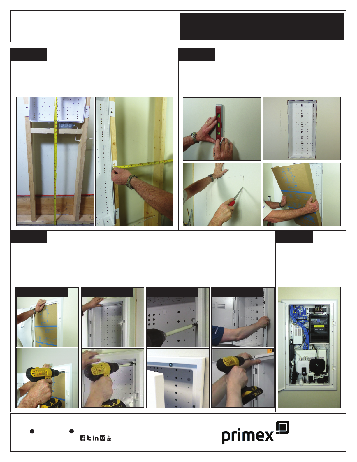
MDE Accessories Verge MDE
P2100, P3000, P4200, P6300
452-3113
Product Description Part #
Cat5e, 110 IDC, 90° HD
Cat5e, 110 IDC, 180° HD
Cat6, 110 IDC, 90° HD
Cat6, 110 IDC, 180° HD
Cat6A, 180°, Unshielded
Cat6A, 180°, Shielded
125-0949-WT
125-0948-WT
125-0947-WT
125-0946-WT
125-1628-WT
125-1629-W T
3-Line RJ12 Voice Jack 125-0959-WT
SC/APC Fiber Keystone w/Shutter 125-0908
Cat5e coupler, HD
Cat6 coupler, HD
RG12 coupler, HD
125-1266-WT
125-1267-WT
125-1268-WT
F-Connector Keystone 125-0961
Blank keystone 125-0960-WT
Customer Premise Outlet (CPO4), 4-Port 125-0911
Single-Gang Wall Plate, 1-Port
Single-Gang Wall Plate, 2-Port
Single-Gang Wall Plate, 3-Port
Single-Gang Wall Plate, 4-Port
125-0957-WT
125-0958-WT
125-0955-WT
125-0956-W T
Decorative Wall Jack, 1-Port
Decorative Wall Jack, 2-Port
Decorative Wall Jack, 3-Port
Decorative Wall Jack, 4-Port
Decorative Wall Plate
125-0951-WT
125-0952-WT
125-0953-WT
125-0954-WT
125-0950-WT
Oversize Wall Plate, 1-Port, Glossy
Oversize Wall Plate, 2-Port, Glossy
Oversize Wall Plate, 3-Port, Glossy
Oversize Wall Plate, 4-Port, Glossy
Oversize Wall Plate, 6-Port, Glossy
125-1241-WT
125-1236-WT
125-1242-WT
125-1243-WT
125-1244-WT
Oversize Wall Plate, 2-Port, W/Cat6 &
Coax, Glossy
Oversize Wall Plate, 2-Port, W/Cat6 &
Coax, Textured
125-1288-WT
125-1237-WT
Single-Gang Angled Wall Plate, 2-Port 125-0984-WT
Fiber Transition Case (FTC)
FTC - w/Screw Cap
FTC - w/Single SC/APC Adapter
FTC - w/ext. Adapter Mount
125-0945
125-0873
125-0849
Fiber Transition Outlet (FTO)
FTO-w/1 SC/APC Adapter
FTO-w/Integrated Splice Tray
125-0889
125-0879
Hurricane Clip (12/pk) 125-0239
3/4”-1/2” Reducer
1”-3/4” Reducer
125-1022
125-0936
Product Description Part #
MDE Key Lock (1pc) 125-1073
MDE Hex Lock (1pc) 125-1678
Retrofit Frame Extender, P2100 (20/box)
Retrofit Frame Extender, P3000 (12/box)
Retrofit Frame Extender, P4200 (12/box)
125-1532
125-1533
125-1534
Rail Mounting System (RMS)
7” RMP w/RMB2(x2), pushpins (x10)
7” RMP w/RMB(x2), pushpins (x10)
7” RMP w/RMK(x2), pushpins (x10)
10” RMP w/RMB2(x4), pushpins (x10)
10” RMP w/RMB(x4), pushpins (x10)
10” RMP w/RMB2(x2)/RMK(x2), pushpins
(x10)
125-1655
125-1656
125-1657
125-1658
125-1659
125-16 6 0
Universal Mounting System (UMS)
Universal Mounting Plate (UMP)
10” UMP w/5’ tape, pushpins (x10)
125-0770
125-1623
Shelf Mounting System (SMS)
SMS Shelf (single), 2’ mounting tape, 10x
pushpins
SMS Shelf (single), 10x pushpins
SMS ‘Service Divider’ Kit (dual), 10x pushpins
SMS Shelf (bulk/18), 5’ mounting tape,
10x pushpins
125-1729
125-1541
125-1542
125-1522
33’ Roll Of Mounting Tape
10’ Roll Of Mounting Tape
125-0779
125-1274
Mounting Plate Pushpins (100/bag)
Mounting Plate Pushpins (10/bag)
125-0829
125-1535
8-Port Cat5e Data Module
8-Port Cat6 Data Module
8-Port Voice RJ31x Module
6-Port Cat6a Data Module
8-Port Voice Cat6 w/RJ45 Module
1x8 Port 4 Line w/RJ45 Voice Module
125-0986
125-1035
125-0987
125-0975
125-0977
125-0976
Cat6/Coax Combo Module
Cat6A/Coax Combo Module
Triple Play Combo Module (Cat6/Voice/Data)
1X8 RJ45 w/1X8 Splitter Combo Module
125-16 65
125-1666
125-16 67
125-1750
2-Way Coax Splitter (horizontal)
4-Way Coax Splitter (vert/horiz)
6-Way Coax Splitter (vert/horiz)
8-Way Coax Splitter (vert/horiz)
125-16 61
125-1574
125-1575
125-1576
Electrical Installation Kit
360° Electrical Rotating Outlet
125-1355
125-1547
This manual suits for next models
3
Other Primex Enclosure manuals