Princip VETRONICS 760 User manual

Installation guide for telematic unit
VETRONICS
760
Princip a.s.
Member of W.A.G. payment solutions, a.s.
Hvězdova 1689/2a |140 00 Prague |Czech Republic
Tel.: +420 236 089 900
e-mail: servis@princip.cz
www.princip.cz

-2-
1. INTRODUCTION
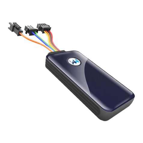
Telematic unit Vetronics 760 is an electronic device designed for fixed installation into vehicles. It is attached to
the vehicle's power, external GPS antenna and optionally vehicle's CAN bus. The unit is designed for use in cars,
trucks and commercial vehicles, with standard 12V or 24V power system. This manual provides information necessary
for the installation of mobile units in vehicles.
The installation of the mobile units should be done by trained personnel, preferably by an authorized automotive
service. It is possible to book a mounting training at the Princip company.
Warning: Vetronics 760 is not fully backwards compatible with older generations of the telematic unit from
Princip. If you are replacing an older unit for Vetronics 760, you need to check the original cable harness very
carefully. See chapter 3.7.
2. SAFETY INSTRUCTIONS
In order to prevent fire, electric shock, injury to the user or other people and damage to the telematic unit or
vehicle, please obey following safety precautions:
·Never place the unit in locations where it is likely to cover the driver's field of vision, or where unit can
cause injury to the driver, accident or where it can affect driving.
·Do not place the unit in an area outside the cabin of the vehicle (e.g. In the engine compartment) where
the temperature range, vibration, humidity or dust can exceeds permitted levels.
·When fitting, ensure that the power supply meets the requirements of the manufacturer (12V-24V) and /
or standards for on-board network for motor vehicles according to ECE. Observe the polarity of the supply
voltage. Power wires must be connected through a fuse (max. 3A) to avoid short-circuit.
·Warranty does not apply to cases when a power supply does not meet the requirements of the
manufacturer or the unit is connected reversing the polarity of the power supply.
·During installation, make sure to avoid accidentally touching the wires not connected to ground, live parts
of the power system or any part of the electric vehicle. Such accident can cause not only destruction of
the mobile unit, but also damage to the vehicle's systems. Manufacturer bears no responsibility for such
damages.
·Installation must not interfere with other systems of the car (alarm, radio, airbags, tachograph etc.) e.g.
electromagnetic radiation of GSM transmission or mechanical damage wires.
·We recommend to disconnect the car battery from the electrical system that before installation
(especially when connecting the CAN bus).
·The unit is not user serviceable. In case of malfunction contact the service centre. Warranty doesn't cover
any unauthorized intervention.
·The unit is intended for firm installation in a vehicle. Frequent reinstallation may cause damage to the unit
and wear antenna connector. Thus caused damage is not subject to manufacturer's warranty.
·When choosing the location of the unit, make sure that the surface, on which it consolidates, is strong
enough with regard to the weight of the unit. When choosing the location of the unit is also important to
take into account the length of the GPS antenna lead.
·GPS Antenna lead (3m) may be extended, but it may have an adverse effect on signal quality. Do not
extend the antenna lead unofficial extension cords. If necessary, use an antenna with longer cable (5m).

Vetronics 760
-3-
3. UNIT MOUNTING
The unit can be fastened by tightening straps using four mounting points on the unit. A solid "velcro" or double-
sided adhesive tape can be also used to secure the unit. Before bonding, it is important to clean the contact surfaces
from dust, grease, water and other dirt.
Warning: Due to the nature of some unit functions (eg. Driver’s Style Rating), it is essential that the unit is
installed in the vehicle firmly.
3.1. Description of basic parts
The following figure shows the unit from the side and from the top.
3.2. micro SIM card (3FF)
For the proper function of the GSM module in the unit, it
is necessary that the inserted micro SIM card has a deactivated
PIN. You can do this on your mobile phone before inserting a
micro SIM card into the unit.
Open the rear plastic cover of the unit and insert the
micro SIM card into the holder as shown in the illustration.
SIM card contacts must point to the drive. The contact pads on
the SIM card and on the SIM card holder in the unit must be
clean. The correct orientation of the SIM card defines the cut
corner of the card.
Warning: Insert the micro SIM card when the unit is powered off.
3.3. Seal
The rear plastic cover of the unit can be sealed with a special self-adhesive seal depending on the agreement
with customer. The purpose is to avoid any unauthorized interference with the unit.
MCX connector for
GPS antenna
Slot for SIM card is
located under the
bottom lid
Mounting points
Cable harness
connector
Type and serial
number label
Status LED’s

-4-
3.4. Connecting of the cable harness
The power supply must be connected to the three power points:
Clamp „31“–Brown wire to the vehicle ground.
Clamp „30“–The red wire to the supply voltage before the key (supply voltage is permanently present) in the
range of 12-24V via fuse 2A.
Clamp „15“–Black-gray wire to the supply voltage behind the key (supply voltage is present only when the
switch box is on) in the range of 12-24V via fuse 2A.
3.5. Connecting to the 24V power system
Vetronics units can also be mounted on trucks and vehicles with 24V supply. In this case, certain demands are
placed on the quality of the onboard power network to which the unit is connected. There are a number of specific
problems for vehicles, such as the use of disconnectors in both the positive and negative branches, various high-
interference devices, the use of welding kits and starter carts. Unfortunately, the condition of the on-board network
is often underestimated.
In cases of obvious damage to the unit by overvoltage or discharge, the guarantee cannot be accepted.
3.6. Connecting a vehicle with 24V supply with disconnector and 12V branch
If the vehicle is equipped with a battery disconnector or with a 12V branch, consult an appropriate connection
with the mobile unit manufacturer.
Warning: In case of improper installation the unit or the vehicle may be damaged.
3.7. Connecting and checking VW AMP connector
The standard cable harness is supplied with 30 wires and is 1m
long with the VW AMP connector ending. It provides mobile unit
connection to power supply from the vehicle's on-board network and
the connection of other peripherals. The length of the cable can be
adjusted for installation. Unused wires must be insulated. In any case,
do not insert the VW AMP connector into the unit before checking the
power connection.
To check the connections, turn on the key and check the
presence of voltage on all VW AMP pins with a voltmeter.
After checking, set the connector lock to "unlocked" position and
plug the connector into the mobile unit with the harness pointing
towards the antenna connector. Finally, switch the lock to "locked" position. The locked connector can be sealed with
wire loop through sealing eyes or with a sticker.
AMP connector pin numbering (contacts point of view) Locking system of AMP connector

Vetronics 760
-5-
3.8. Table of signals and wire colors
číslo pinu na
konektoru AMP signál zkratka signálu barva
vodiče
doplňková
barva vodiče
1 Power supply “KL30”PWR_IN red
2 Power supply for external devices, adjustable 3.3V / 5V PWR_ADJ -
3
Ground
“KL31“
GND
brown
4 Ground “KL31“GND brown white
5 Input for Business/Private switch IN1 white
6
-
-
-
7 - - -
8 - - -
9
Wiegand
D1
/ USL
input
WIE / U
SL
_IN
violet
blue
10 - - -
11 Digital input (wake up function) IN5 -
12
Ignition input
”KL15”
IGN
black
grey
13 Dallas input / Wiegand D0 DALLAS1 violet green
14 Power supply for private/business switch LED LED_S red white
15
Service
RS232 RX
RSI1
-
16
Service
RS232 TX
RSO1
-
17 Power supply for Dallas chip reader LED (anode) LED_D red green
18 Output for Dallas reader LED (cathode) OUT1/IN7 green
19
Output for buzzer
OUT2/IN8
green
yellow
20 - - -
21 - - -
22
Universal bus input
UAR
-
23 - - -
24 Ground ”KL31”GND brown green
25
RS232 TX
(trm)
RSO2
-
26 RS232 RX (trm) RSI2 -
27 USL output USL_OUT -
28
-
-
-
29 - - -
30 - - -
31
CAN
bu
s c0 (low)
CAN0_L
orange
brown
32
CAN
bus
c
0 (high)
CAN0_H
orange
black
Warning: The older version of connecting cables may vary. If your harness contains a different colour scheme or
a different number of wires, or if you need to use the optional signals that are not available at wiring harness, contact
the manufacturer.
Incorrect connection may result in injury or damage for which the manufacturer is not liable!
4. Placing antennas in the vehicle
The unit contains internal GSM antenna and external GPS antenna. If there is insufficient reception of GSM signal
after installation try to change the location of the unit. Do not place the unit in a closed metal compartment.
The GPS antenna is designed for hidden mounting in the vehicle cabin. Place the antenna so that the signal can
be received from the largest part of the sky. The antenna should lie horizontally, with the bulging part of the plastic
cover facing upright with a direct view to the sky. In practice, this cannot usually be ensured, and therefore a
compromise solution is often chosen. The antenna may be placed on or below the dashboard as close as possible to
the windscreen, near the longitudinal axis of the car, as shown on the picture. The lower part of the antenna is
provided with a magnet for mounting on the metal parts of the vehicle. A velcro or double-sided sticker can be used
for fastening the antenna. The antenna is waterproof, but not intended for mounting outside the vehicle.
The metal bottom of the antenna is conductively connected to the ground of the unit. If the antenna touches the
metal parts of the vehicle body with a grounded negative pole, then the unit must not be plugged in before the
disconnector on the negative pole!

-6-
GPS and GSM signals penetrate glass, plastics and other non-conductive materials. The GPS antenna must not be
covered with conductive material in the direction of reception of the signal.
Warning: Some vehicles have metal-plated windscreen. These glasses do not allow electromagnetic wave
propagation. In these cases, use a roof antenna or consult the location of the antenna with the manufacturer. There
are areas without the metallization in some metalized windscreens which can be used for antennas.
5. Installation of optional peripherals
5.1. Business/private journey switch
User can use this switch to select the journey type. If the LED lights up, it is a private journey.
pin
harness
signal
switch
14
red
-
white
power
LED
anod
e
5 white input IN1 LED cathode, swith
4 brown-white ground switch
5.2. DALLAS chip reader (driver identification)
Dallas chip reader is used to identify the driver in the vehicle. When the unit is activated the LED in the center of
the sensor is permanently lit. The driver is identified by attaching the Dallas chip to the reader. The unit records the
chip code and the sensor light goes out. Logging out can be done by reattaching the same chip or turning off the
ignition. The sensor has five wires but only four are used. Usually, select the red light and therefore connect the
brown sensor wire. For green light connect the green wire. Some sensors from other manufacturers may have
different color marking on the wires
pin harness reader signal
13
violet
-
green
white
DATA
24 brown-green grey GND
18 green yellow OUT1, LED cathode
17
red
-
green
brown
red
LED
anode
- - green green LED anode
5.3. Buzzer (driver identification)
Acoustic signal for Dallas chip reader. When the unit is activated, the buzzer start to beep for reminding the
driver to use the Dallas chip for identification. The beep signal continues until the chip is attached to the reader.
pin harness buzzer signal
12 black-grey red IGN
19
green
-
yellow
black
output
OUT2

Vetronics 760
-7-
5.4. RFID readers (driver identification)
Vetronics unit supports variety of RFID readers with several types of communication interfaces including RS232,
UART, Dallas and Wiegand.
There are a large number of wireless RFID readers on the market. If you need to connect another type of sensor,
contact the manufacturer. If the reader is hidden beneath the dashboard, you can lead the LED on the dashboard.
The external LED should be connected so that the cathode is connected to green and the anode to the red-green (or
red-white) wire.
5.5. Other peripherals
The specific connection of optional peripherals, e.g. analogoue inputs, tachograph, Dallas sensors, fuel gauges
etc. must be consulted with the manufacturer of the unit
6. Connection to the OBDII service connector
The unit can be connected to the CAN bus in private car via OBDII connector. Then, the unit can read important
data (mileage status, fuel level, diagnostic trouble codes...) directly from CAN bus.
OBDII connector with CAN bus is mandatory for vehicles in European Union since 2000 for gasoline, respectively
since 2003 for diesel vehicles. Standard 16-pin socket must be placed in a location accessible to the driver no more
than 50 cm from the steering wheel. Unit must be configured for specific vehicle manufacturer and type in order to
read this data.
16 pole OBDII socket, driver’s point of view
6.1. Wiring
ARD2 reader with Dallas communication HID reader with Wiegand communication
pin
harness
unit
reader
pin
harness
unit
reader
12
black
-
grey
IGN
power
12
black
-
grey
IGN
power
12 black-grey IGN reader enable 9 violet-blue D1 data 1
13 violet-green Dallas data 13 violet-green D0 data 0
24
brown
-
green
GND
GND
24
brown
-
green
GND
GND
18 green OUT1 LED cathode 18 green OUT1 LED cathode
19 green-yellow OUT2 buzzer 19 green-yellow OUT2 buzzer
AMP connector OBDII connector
signal
pin
harness
connection
OBDII
signal
CAN-L 31 orange-brown OBD basic 14 CAN-L
CAN-H 32 orange-black OBD basic 6 CAN-H
UIN
1
red
optional
16
vehicle power
(“KL30”)
GND 3 brown optional 4 or 5 ground (“KL31“)

-8-
6.2. Connection description
Connect the twisted pair of wires in harness to the OBDII diagnostic connector according to the table above, ie.
orange-brown wire to the OBDII connector pin No. 14 and the orange-black wire to pin 6 of the OBDII connector. The
OBDII connector itself must remain free for connection of diagnostic tools.
On the OBDII connector there is also a permanent on-board voltage ("KL30") on contact 16 and a ground ("KL31")
on contact number 4. These can be used to power the unit. Therefore, the part of the standard unit connection can
be made directly on the OBDII connector.
In the vehicles, where the unit cannot be connected to the OBD connector for various reasons is possible to
connect the unit to another CAN bus or use DLC for older FORD vehicles. Such involvement should be consulted with
the manufacturer.
7. Checking and diagnostics of mobile unit
All mobile units manufactured by Princip are double checked before delivery to the customer. It is very unlikely
that new unit is malfunctional. Follow these instructions if the unit does not operate properly.
7.1. Check connections of basic signals
Ensure that the correct voltage values are present on the connector and that the wires are properly grounded.
All voltages are measured against the vehicle's ground point.
·At least one of pins No. 3, 4 or 24 must be connected to the ground,
·if the ignition is turned off, the on-board voltage must be presented on pin No. 1 only,
·if the ignition is turned on, the on-board voltage must be presented on pin No. 1 and 12.
If the wiring is not correct, fix the wiring and check again. After that, plug the connector into the unit and verify
that the AMP connector is properly inserted in the socket and the lock is securely closed.
Note: If all the signals are correctly connected but the unit still does not indicate the activity by red LED, contact the
manufacturer.
7.2. Verifying basic functions with diagnostic LEDs
Diagnostic LEDs are used to verify the basic functions of the unit. Each of the three LEDs (green, orange, red) can
either light, blink or remain off. Meanings of the LED states are described in the table below. Follow this procedure:
·Place the vehicle outside garage, so that GPS signals can be received from satellites.
·Turn the ignition key on to activate the unit.
·Check the three indication LEDs on the unit.
·The status can change. The final status is reached in max. 2 minutes.
Each of the three LEDs (green, orange, red) can either be lit, flash or remain off. The status of each LED is
described in the table below.
The red LED can also blink for a few seconds after the ignition is switched off.
Diagnostic LED status
color function off flash on
green GSM not logged to the operator
(SIM error or low GSM signal)
Logged to the operator, no
GPRS connection GPRS connection
orange GPS no GPS signal received signal from at least
one satellite 3D postition
red other ignition not detected
ignition detected, no CAN
messages receiving
ignition detected, receiving CAN
messages

Vetronics 760
-9-
7.3. Checking Business/Private switch
With the ignition key turned on and switched to the "private journey" position, the built-in LED on the switch
lights on. If the LED does not light up, check the wiring of the switch. In the "private journey" position, there must be
a zero voltage on the brown-white and white wires and the voltage 1 - 2.5 V must be on the contact marked "+".
When switching to the "business journey" position, the white wire must have a voltage greater than 5 V And "+"
contact approx. 4 V.
7.4. Checking Dallas chip/RFID reader
There are several variants of the chip readers. It is necessary to select the proper variant and to connect the
reader according to the table in the Chapter 5. After the ignition key is switched on, the red light in the center of the
reader lights up and after a few seconds a beeping starts. By attaching the identification chip, the LED goes off and
the beeping stops.
If the indicator light does not light up when the power is turned on, verify that the voltage on the red-green wire
is about 3.8 V. Check the LED in the sensor by connecting the green wire and cathode diode to the ground for a
moment. The functional LED should light up. When the LED does not go out after the chip is attached, check the
reader connection.
The RFID reader works in terms of LED and audio signals in the same way as Dallas chip reader.
Note: The Dallas chip reader or RFID reader is activated based on customer requirements when ordering. If the
sensor does not work, even if the wiring is correct, the unit may be defective. Contact your supplier if necessary.
7.5. Checking unit systems via web interface
You can easily diagnose the drive through the web interface, which can be found at http://diag.princip.cz
7.6. Checking unit systems using diagnostic SMS
Diagnostic SMS checking is used to verify the basic functions after mounting the unit. The check can be made
according to the following procedure:
•From the mobile phone, send an SMS to the phone number of the unit with the letter "S" or "s" (status).
•For SMS card units with 898823900000xxxxxxxx ICCID form, you can send an SMS in the form Axxxxxxxx, where
xxxxxxxx is the ICCID ending number on the SIM card or the SMS containing SN of the unit in the form S7xxAxxxxx, on
the phone number +420602229317. E.g. For ICCID 89882390000001234567 the SMS is: A1234567
If the unit does not respond, it is necessary to check the GSM system. The response format for the diagnostic
message is as follows:
OK/ERR/OFF GPS=ss u=xA=aengprs=galive=tt aux=app(t) trm=app(t) SN=nnnnnnnn HW=h.hh FW=f.f.f.f ccc ……..
Individual groups of SMS information mean:
OK/ERR/OFF
It is assumed that for testing the GPS function you must wake up the unit by turning on the ignition key.
Therefore, the first item is whether the unit detects a voltage signal behind the key and whether it has any
information from GPS.
value meaning
OK
ignition is detected, GPS module has enough signal from satellites
ERR
ignition is detected
, GPS modul
e
has not determined the position yet
OFF ignition is not detected
GPS
Item “GPS=xxx“, where xxx is a number of receiving GPS satellites. Signal from at least four satellites is sufficient
for the satisfactory operation. There are usually 8-12 satellites in place with good views of the sky. The low number of
signals in such a location may be related to the improper installation of the GPS antenna.

-10-
u
Item “u=x“indicates the presence of the UIN1 main power supply and the UIN2 "voltage behind the key" signal
according to the table:
value
UIN1
UIN2
u=0 off off
u=1 on off
u=2
off
on
u=3 on on
A
Item “A=a“indicates the status of the business/private switch. It can only have two values, either "A = 0" (private
journey) or "A = 3" (business journey).
engprs
If "engprs = g" has a value "engprs = 1", it indicates that the GPRS feature is enabled in the configuration (but
does not say anything about whether the APN is set or whether the service is enabled by the SIM card). "engprs = 0"
means that GPRS configuration is disabled.
alive
Item ”alive=tt“shows the set time from switching off the ignition until the unit starts sleeping (transition to low-
power mode). The time interval can be expressed in minutes (eg. "alive = 30m") or hours (eg. "alive = 8h"), "alive =
none" means prohibited sleeping.
aux
Item ”aux=app“indicates the function (application) setting on the service line. An item is listed only when this
function is set. If the correct activity on this line is detected, the brackets are expanded, indicating the time of this
activity in seconds, minutes or hours (eg. (5s), (99m), (24h)). If activity has not been detected (from restart or within
99 hours), "(-)" is displayed. The activity means detecting of data on the line. In case of formatted data, the format
and the checksum of the received message are also checked. For some features the activity is not checked.
trm
Item ”trm=app“indicates same information as ”aux=app“just for terminal line.
id
Item ”id=src(t)“contains information about the driver's log-in source with the most recent login information.
SN, HW a FW
These items indicate the following unit information:
"SN=nnnnnnnnnn" –serial number of the unit
"HW=h.hh" –hardware type of the unit
"FW=f.f.f.f" –firmware version of the unit
fms/obd/vwm/off
This items indicate CAN bus mode settings and examples of recognized information from this bus. The first two
parameters separated by the "/" character include the type of the bus or the application that is set in the
configuration. Behind this item, the information you see is different by the settings. There may be information about
mileage, tank fuel, mileage and time for service, etc.

Vetronics 760
-11-
7.7. What to do if the fault failed to remove?
If you have done all of the previous checks and the unit is still not fully functional, try to connect another unit
that you know it works. If this unit does not communicate it will probably be a connection error and try repeating the
tests. If the reference unit is fully functional there is no error in the connection but in the checked unit. Do not open
or perform any other interference with the internal system in any way. There are no components in the unit that
could be repaired without other specific tools so send it to the vendor for complaint procedure. The product waives
all warranties if it has been mechanically damaged or the warranty seal has been violated.
Before sending the unit to repair you can use the telephone consultation with the technician from the service
department. In many cases a malfunction can be removed remotely without the need to send the unit. Our service
department is able to remotely diagnose and reconfigure or change the firmware.
7.8. Quality
We pay great attention to the quality of production. Each unit undergoes many tests in production and the
results are recorded. The final inspection is performed prior to distribution. However, the unit may not function after
mounting. Usually, there is a problem with the installation of the unit. However, the supplied unit may not work.
These cases are addressed responsibly, and due to ISO quality management, each case is evaluated and serves to
improve individual processes for the future. Thank you for your possible comments.
We wish you many mileage with our product.

-12-
Princip a.s.
Member of W.A.G. payment solutions, a.s.
Hvězdova 1689/2a |140 00 Prague |Czech Republic
Tel.: +420 236 089 900
E-mail: servis@princip.cz
www.princip.cz
Rev 4, september 2018
Table of contents
