Bosch Truvo User manual

| 3
Bosch Power Tools 1 609 92A 3FC | (4.8.16)
Truvo
Truvo
2
1
1
7
6
1
4
5
3
45
OBJ_BUCH-2841-002.book Page 3 Thursday, August 4, 2016 6:22 PM

16 | English
1 609 92A 3FC | (4.8.16) Bosch Power Tools
Nur für EU-Länder:
Gemäß der europäischen Richtlinie 2012/19/EU müs-
sen nicht mehr gebrauchsfähige Messwerkzeuge und
gemäß der europäischen Richtlinie 2006/66/EG müs-
sen defekte oder verbrauchte Akkus/Batterien getrennt
gesammelt und einer umweltgerechten Wiederverwen-
dung zugeführt werden.
Nicht mehr gebrauchsfähige Akkus/Batterien können direkt abgegeben
werden bei:
Deutschland
Recyclingzentrum Elektrowerkzeuge
Osteroder Landstraße 3
37589 Kalefeld
Schweiz
Batrec AG
3752 Wimmis BE
Änderungen vorbehalten.
English
Safety Notes
Read and observe all instructions. The integrated pro-
tections in the measuring tool may be compromised if the
measuring tool is not used in accordance with the instruc-
tionsprovided.SAVETHESEINSTRUCTIONSFORFUTURE
REFERENCE.
Have the measuring tool repaired only through qualified special-
ists using original spare parts. This ensures that the safety of the
measuring tool is maintained.
Do not operate the measuring tool in explosive environments,
such as in the presence of flammable liquids, gases or dusts.
Sparks can be created in the measuring tool which may ignite the dust
or fumes.
OBJ_BUCH-2841-002.book Page 16 Thursday, August 4, 2016 6:22 PM

English | 17
Bosch Power Tools 1 609 92A 3FC | (4.8.16)
The measuring tool may not be 100% accurate for technological
reasons. For this reason and to eliminate hazards, familiarise
yourself with the area using other sources of information, such as
building plans and photographs taken during construction, etc.
before carrying out any drilling, sawing or milling work on walls,
ceilings or floors. The accuracy of the measuring tool may be affected
by environmental influences, such the level of humidity or there being
otherelectronicdevicesnearby. The structure and conditionofthewalls
(e.g. damp, building materials containing metal, electrically conductive
wallpaper, insulating materials, tiles) and the number, type, size and po-
sition of the objects may distort the measurement results. Inaccurate
readings may be caused, for example, by the building materials (espe-
cially plaster and tiles) being made damp through high humidity.
These influences may result in the indicator LED lighting up green de-
spite there being an object within range of the sensor, or in the indica-
tor LED lighting up red despite there not being an object within range
of the sensor.
Make sure that you are properly earthed when taking measure-
ments. If you are not properly earthed (e.g. by wearing insulating foot-
wear or by standing on a ladder), it will not be possible to locate live
cables.
Product Description and Specifications
Intended Use
The measuring tool is intended for the detection of ferrous metals
(e.g. reinforced steel), non-ferrous metals (e.g. copper pipes) as well as
“live” wires/conductors in walls, ceilings and floors.
Product Features
The numbering of the product features shown refers to the illustration of
the measuring tool on the graphic page.
1Marking aid
2Signal LED
3On/Off switch
4Latch of battery lid
5Battery lid
6Serial number
7Sensor area
OBJ_BUCH-2841-002.book Page 17 Thursday, August 4, 2016 6:22 PM

18 | English
1 609 92A 3FC | (4.8.16) Bosch Power Tools
Technical Data
Assembly
Inserting/Replacing the Batteries
Alkali-manganese batteries are recommended for the operation of the
measuring tool.
To open the battery lid 5, press on the latch 4and fold the battery lid up.
Insert the batteries. When inserting, pay attention to the correct polarity
accordingtothe representation on the inside ofthebattery compartment.
Remove the batteries from the measuring tool when not using it
for extended periods. When storing for extended periods, the batter-
ies can corrode and self-discharge.
Digital Detector Truvo
Article number 3 603 F68 2..
Maximum scanning depth*:
– Ferrous metals
– Non-ferrous metals (copper pipe)
– Copper conductors (live)**
70 mm
60 mm
50 mm
Calibration automatic
Automatic switch-off after approx. 10 min
Operating temperature 0°C...+40°C
Storage temperature –20 °C...+70 °C
Relative humidity 30 ... 80 %
Batteries 3 x 1.5 V LR3 (AAA)
Operating lifetime (alkali-manganese batteries)
approx. 5h
Weight according to EPTA-Procedure 01:2014 0.15 kg
* depending on material and size of the objects as well as material and condition of the
base material (walls, ceilings, floors)
** less scanning depth for wires/conductors that are not “live”
In terms of accuracy and scanning depth, the measurement result can be infe-
rior in case of unfavourable surface quality of the base material.
The measuring tool can be clearly identified with the serial number 6on the type plate.
OBJ_BUCH-2841-002.book Page 18 Thursday, August 4, 2016 6:22 PM

English | 19
Bosch Power Tools 1 609 92A 3FC | (4.8.16)
Operation
Initial Operation
Protect the measuring tool against moisture and direct sun light.
Do not subject the measuring tool to extreme temperatures or var-
iations in temperature. As an example, do not leave it in vehicles for
a long time. In case of large variations in temperature, allow the meas-
uring tool to adjust to the ambient temperature before putting it into
operation. In case of extreme temperatures or variations in tempera-
ture, the accuracy of the measuring tool can be impaired.
Avoid heavy impact to or falling down of the measuring tool.
Switching On and Off
Before switching the measuring tool on, make sure that the sensor
area 7 is notmoist. Ifrequired,drythemeasuringtool using a softcloth.
To switch on the measuring tool, slide the On/Off switch 3
downwards.
Afterashort self-test, the tool isreadyfor use. The readiness ofuseis indi-
cated when the signal LED 2illuminates. If the signal LED 2fails to illumi-
nate after switching on the tool, you must replace the batteries.
To switch off the measuring tool, slide the On/Off switch 3
upwards.
When no measurements are carried out for approx. 10 minutes, the
measuring tool switches off automatically in order to extend the service
life of the batteries.
Note: The on/off switch 3will remain in the “on” position when the
measuring tool switches itself off automatically. To switch the measuring
tool back on, switch it off first before switching it on again.
OBJ_BUCH-2841-002.book Page 19 Thursday, August 4, 2016 6:22 PM

20 | English
1 609 92A 3FC | (4.8.16) Bosch Power Tools
Operating Modes
The measuring tool detects objects below the sensor area 7.
Detecting Metal Objects
After switching on, the signal LED 2lights up green.
Position the measuring tool on/against the surface being detected and
move it sideways.
– If no metal object is visible in the base material, then the signal LED 2
continues to illuminate green and no signal tone sounds.
– When the measuring tool comes closer to a metal object, the signal LED
2firstlightsupyellowandchangestored the closer it comestothemetal
object. As soon as the signal LED lights up red, a signal tone is also emit-
ted, the pitch of which rises the closer it comes to the metal object.
– Over a metal object, the signal LED 2illuminates red and a signal tone
is emitted at maximum pitch.
Even with a yellow signal LED 2, a metal object may be located be-
low the sensor area. Small or low-lying metal objects are located in
the vicinity of the sensor or the wall material impairs the measurement
results.
Signal LED Explanation
green no object detected
yellow – metal object in the vicinity of the sensor
– small or low-lying metal object within
the sensor area or
– impairment of the sensor due to unfa-
vourable wall material
red and continuous tone metal object detected in the sensor area
red flashing (fast) and
intermittent sound “live” wire/conductor detected
OBJ_BUCH-2841-002.book Page 20 Thursday, August 4, 2016 6:22 PM

English | 21
Bosch Power Tools 1 609 92A 3FC | (4.8.16)
After moving over the surface the first time, the posi-
tionof the metal object is only roughly indicated. If you
move the measuring tool over the metal object several
times, the object detection will become increasingly
precise. After moving over the metal object several
times (without lifting the measuring tool from the base
material), its position can be indicated very accu-
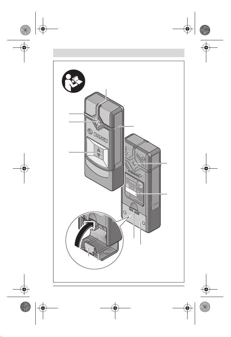
rately: if the signal LED 2illuminates red and the signal
tone sounds, the metal object is below the sensor area. When the pitch of
the signal tone is highest, the metal object is located below the centre of
the sensor.
Scanning for “Live” Wires
The measuring tool indicates wires, which carry voltage between 110 V
and 240 V and a frequency corresponding to the widely used standard
(AC with 50 or 60 Hz). Other wires (carrying DC, higher/lower frequency
or voltage) as well as non-“live” wires/conductors cannot be found relia-
bly, but are possibly indicated as metal objects.
The detection for “live” wires/conductors takes place automatically with
every measurement. When a “live” wire/conductor is detected, the signal
LED 2flashes red and an intermittent signal tone sounds with rapid tone
sequence. Move the measuring tool repeatedly over the surface to locate
the “live” wire/conductor more precisely. After moving over the surface
several times, the position of the “live” wire/conductor can be indicated
very accurately.
Itiseasiertofindlivecables if electricity consumers(e.g.lights,appliances)
are connected to the cable being searched for and are switched on. Switch
off electricity consumers before drilling, sawing or milling into the wall.
Note: Always ensure that you hold the measuring tool firmly without
gloves to enable a good grounding. Also ensure that ladders/scaffolding
must be grounded. Avoid ladders/scaffolding whose supports have plas-
tic caps underneath them. Do not wear insulating footwear.
It may not be possible to find live cables in certain conditions (e.g. behind
metal surfaces, behind surfaces that are very dry or very damp). If the in-
dicator LED 2lights up yellow or red over a large area, the material is elec-
trically shielded and you will not be able to find live cables accurately.
OBJ_BUCH-2841-002.book Page 21 Thursday, August 4, 2016 6:22 PM

22 | English
1 609 92A 3FC | (4.8.16) Bosch Power Tools
Working Advice
To avoid affecting the measurement, do not hold the measuring tool within
range of the sensor. This will enable you to obtain more accurate measure-
ment results.
Marking Objects
Detectedobjectscanbe marked as required. Theouteredgesofanobject
are indicated by the colour change of the signal LED 2from yellow to red.
The centre of the metal object can be determined by the pitch. Using a
pen, mark the sought after location at the top and the side marker aids 1.
Continuous Flashing Green/Yellow/Red
Ifthe signal LED 2flashesalternately green, yellow and red,even when no
metal object or no “live” cable is in the vicinity, the measuring devicemust
be sent in for service.
Maintenance and Service
Manual Calibration
If the signal LED 2illuminates red or yellow, even when no metal is in the
vicinity of the measuring tool, the tool must be recalibrated.
– To do this, switch the measuring device on using the On/Off switch 3.
– Remove a battery from the switched on measuring device.
– While the battery is removed, switch the measuring device off using
the On/Off switch 3.
– Reinsert the batteries into the measuring device (pay attention to the
polarity!).
– Now remove all objects in the vicinity of the measuring device (includ-
ing wrist watches or rings of metal) and hold the measuring tool up in
the air.
– SwitchthemeasuringdeviceonusingtheOn/Offswitch 3and off again
within 3 seconds. The signal LED 2of the measuring device will flash
red in slow succession during the 3 seconds to indicate that it is ready
to calibrate.
– Switch the measuring device back on within 0.5 seconds. The calibra-
tion is initiated and takes about 6 seconds. The signal LED 2will flash
green for 6 seconds in quick succession, the calibration is being per-
formed. Now the device is once more ready for operation and the
signal LED 2illuminates solid green.
OBJ_BUCH-2841-002.book Page 22 Thursday, August 4, 2016 6:22 PM

English | 23
Bosch Power Tools 1 609 92A 3FC | (4.8.16)
Note:Ifthe sequence of switchingoff then on againis not followed, nocal-
ibration is performed. The signal LED 2remainseither yellow or red, even
though no metal is located within the vicinity. In this case, repeat the cal-
ibration.
Troubleshooting – Causes and Corrective Measures
Cause Corrective Measure
Signal LED 2 does not illuminate.
Measuring tool is not
switched on Switch the measuring tool on.
Measuring tool has
switched itself off Switch the measuring tool off and then on again.
Batteries have not
been inserted or been
inserted incorrectly
Insert batteries. Pay attention to the polarity.
Flat or rechargeable
batteries inserted Replace batteries. Do not use rechargeable bat-
teries.
Signal LED 2 illuminates yellow or red, even though no metal is
located within the vicinity (warning of metal objects).
Ambient temperature
is too high/too low Only use the measuring tool within the specific
temperature range of 0 °C–40 °C.
Severe temperature
change Wait until the measuring tool acclimates to the
ambient temperature.
Auto calibration not
successful
Perform a manual calibration.
* Therefore, please also observe other information sources (e.g. construction plans)
before drilling, sawing or routing into walls, ceilings or floors.
OBJ_BUCH-2841-002.book Page 23 Thursday, August 4, 2016 6:22 PM

24 | English
1 609 92A 3FC | (4.8.16) Bosch Power Tools
Signal LED 2 lights yellow or red over large measuring area on the
wall (warning of metal objects).
Many, closely spaced
metal objects Pay attention to the pitch of the signal sound to
differentiate between individual metal objects.
Metalobjectsthatare toocloselyspaced,cannot
be detected separately.*
Building materials
containing metal or
reinforcing steel in
the concrete
A reliable detection is not possible with metallic
building materials (e.g. foil-laminated insulation
materials, heat sinks).*
Solid metal objects on
the back of the wall Detection will not be accurate in the presence of
solid metal objects (e.g. radiators).*
Auto calibration not
successful Perform a manual calibration.
Signal LED 2 flashes red over a large measuring area on the wall
(warning of “live” cables).
Improper grounding
of the wall With your free hand, touch the wall at a distance
of 20–30 cm from the measuring tool to ground
the wall.
Cause Corrective Measure
* Therefore, please also observe other information sources (e.g. construction plans)
before drilling, sawing or routing into walls, ceilings or floors.
OBJ_BUCH-2841-002.book Page 24 Thursday, August 4, 2016 6:22 PM

English | 25
Bosch Power Tools 1 609 92A 3FC | (4.8.16)
“Live” cable is not found.
No/atypicalvoltage on
the cable Add voltage to the cable, for example by turning
on light switches assigned to it. The detection of
cables with AC voltages outside of the range
110–240 V, 50–60 Hz isnot reliablypossible.*
Cable is located too
deep. Thescanningdepthisdependentonthebuilding
material and may be less than the maximum
scanning depth.*
Cable runs in
grounded metal pipe. Use the measuring tool to locate the metal pipe.
Measuring tool is not
grounded. Hold the measuring tool firmly without gloves.
Donotstandoninsulatingladdersorscaffolding.
Do not wear insulating footwear.
Shielding building
material or humidity
too low/too high
Detection will not be accurate in the presence of
metallic building materials or building materials
that are too dry or too damp (e.g. if the humidity
is too low or too high).*
Metal object is not located.
Metalobject is located
too deep. Thescanningdepthisdependentonthebuilding
material and may be less than the maximum
scanning depth.*
Metal object is too
small. Thescanningdepthisdependentonthebuilding
material and may be less than the maximum
scanning depth.*
Uncoordinated flashing in colours green, yellow, red
Interference caused
byelectricormagnetic
fields
Keepyour distance from devicesemitting strong
electric or magnetic fields (e.g. computers,
switch mode power supplies).
Cause Corrective Measure
* Therefore, please also observe other information sources (e.g. construction plans)
before drilling, sawing or routing into walls, ceilings or floors.
OBJ_BUCH-2841-002.book Page 25 Thursday, August 4, 2016 6:22 PM

26 | English
1 609 92A 3FC | (4.8.16) Bosch Power Tools
Maintenance and Cleaning
Wipe away debris or contamination with a dry, soft cloth. Do not use
cleaning agents or solvents.
In order not to affect the measuring function, decals/stickers or name
plates,especially metal ones, may not be attached in thesensor area 7on
the front or back side of the measuring tool.
After-sales Service and Application Service
Our after-sales service responds to your questions concerning mainte-
nance and repair of your product as well as spare parts. Exploded views
and information on spare parts can also be found under:
www.bosch-pt.com
Bosch’s application service team will gladly answer questions concerning
our products and their accessories.
In all correspondence and spare parts orders, please always include the
10-digit article number given on the nameplate of the product.
Measurement results inaccurate/implausible
Interfering metal ob-
jects in the area of the
sensor
Removeallinterferingmetalobjects(e.g.watches,
bracelets, rings, etc.) from within range of the
sensor. Do not hold the measuring tool close to
the sensor.
Auto calibration not
successful Perform a manual calibration.
Continuous flashing green/yellow/red,
even when no metal or “live” cable is in the vicinity.
Measuring tool is
defective. Send the measuring tool in for service.
Cause Corrective Measure
* Therefore, please also observe other information sources (e.g. construction plans)
before drilling, sawing or routing into walls, ceilings or floors.
OBJ_BUCH-2841-002.book Page 26 Thursday, August 4, 2016 6:22 PM

English | 27
Bosch Power Tools 1 609 92A 3FC | (4.8.16)
Great Britain
Robert Bosch Ltd. (B.S.C.)
P.O. Box 98
Broadwater Park
North Orbital Road
Denham
Uxbridge
UB 9 5HJ
At www.bosch-pt.co.uk you can order spare parts or arrange the
collection of a product in need of servicing or repair.
Tel. Service: (0344) 7360109
E-Mail: [email protected]
Ireland
Origo Ltd.
Unit 23 Magna Drive
Magna Business Park
City West
Dublin 24
Tel. Service: (01) 4666700
Fax: (01) 4666888
Australia, New Zealand and Pacific Islands
Robert Bosch Australia Pty. Ltd.
Power Tools
Locked Bag 66
Clayton South VIC 3169
Customer Contact Center
Inside Australia:
Phone: (01300) 307044
Fax: (01300) 307045
Inside New Zealand:
Phone: (0800) 543353
Fax: (0800) 428570
Outside AU and NZ:
Phone: +61 3 95415555
www.bosch.com.au
OBJ_BUCH-2841-002.book Page 27 Thursday, August 4, 2016 6:22 PM

28 | English
1 609 92A 3FC | (4.8.16) Bosch Power Tools
Republic of South Africa
Customer service
Hotline: (011) 6519600
Gauteng – BSC Service Centre
35 Roper Street, New Centre
Johannesburg
Tel.: (011) 4939375
Fax: (011) 4930126
E-Mail: [email protected]
KZN – BSC Service Centre
Unit E, Almar Centre
143 Crompton Street
Pinetown
Tel.: (031) 7012120
Fax: (031) 7012446
E-Mail: [email protected]
Western Cape – BSC Service Centre
Democracy Way, Prosperity Park
Milnerton
Tel.: (021) 5512577
Fax: (021) 5513223
E-Mail: [email protected]
Bosch Headquarters
Midrand, Gauteng
Tel.: (011) 6519600
Fax: (011) 6519880
E-Mail: [email protected]
Disposal
Measuring tools, accessories and packaging should be sorted for environ-
mental-friendly recycling.
Do not dispose of measuring tools and batteries/rechargeable batteries
into household waste!
OBJ_BUCH-2841-002.book Page 28 Thursday, August 4, 2016 6:22 PM
Other manuals for Truvo
3
Table of contents
Other Bosch GPS manuals