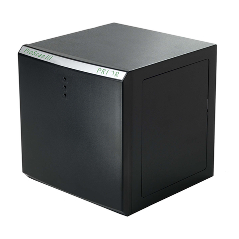
Prior Scientific ProScan III User manual

1
ProScan® III Manual
Visit Prior on the web at
p
r
io
r
.
c
o
m
ProScan®III
Universal Microscope Automation Controller
Manual Version 1.12
Prior Scientific,
Ltd
Prior Scientific, Inc Prior Scientific, GmbH Prior Scientific KK
Cambridge, UK Rockland, MA. USA Jena, Germany Tokyo, Japan
T. +44 (0) 1223 881711 T. +1 781-878-8442 T. +49 (0) 3641 675 650 T. +81-3-5652-8831
E. uksales@prior
.com
Visit Prior on the web at
p
r
io
r
.
c
o
m
Worldwide distribution


© Prior Scientific Instruments Ltd Version 1.12 June 2017 Page 1
ProScan® III Manual
Contents
SECTION 1 IMPORTANT SAFETY INFORMATION 3
SECTION 2 IDENTIFYING AND CONNECTING YOUR SYSTEM 6
2.1 Identifying the parts of the ProScan III controller 6
2.2 Connections 7
2.3 Installing accessories and indicators 8
2.31 Installing stages 8
2.32 Installing focus 9
2.33 Installing filter wheels and shutters 11
2.34 Fourth Axis or Auxiliary Axis equipment 12
2.35 Connecting the Interactive Control Centre 12
2.36 Installing a Lumen 200Pro 12
2.4 Expanding the ProScan III 13
SECTION 3 INSTALLING AND USING THE SOFTWARE 18
3.1 Installing software 18
3.2 Using the program 19
SECTION 4 SOFTWARE COMMANDS 41
4.1 ASCII Commands for RS232 or Virtual COM port 41
4.2 General Commands 44
4.3 Stage Commands 47
4.4 Z Axis Commands 51
4.5 Filter Wheel Commands 53
4.6 Shutter Commands 54
4.7 Lumen Pro Commands 55
4.8 Pattern Commands 56
4.9 Stage Mapping Commands 58
4.10 OEM Commands 59
4.11 Error Codes and Error Tracking Commands 60
4.12 CS152 (Joystick Backwards Compatibility) 61
4.13 Examples for the CS152 Joystick buttons 63
4.14 Add on trigger board commands 64
4.15 Encoders 65
4.16 TTL input/output symbols 68
4.17 TTL Command Set 69
4.18 TTL Programming Advanced Features 70

© Prior Scientific Instruments Ltd Version 1.12 June 2017 Page 2
ProScan® III Manual
SECTION 5 GLOSSARY 73
SECTION 6 RETURNS AND REPAIRS 76
APPENDICES 77
Appendix A: How to use Prior Terminal 77
Appendix B: Principles of Operation ` 80
Appendix C: VLD Connections 86
Appendix D: V31F Connections 87
Appendix E: FTDI speed adjustments 88
Appendix F: Fourth Axis Commands 89
Appendix G: Product Compatibility with the ProScan III 90
Appendix H: Information for customers in China 91
Appendix I: ProScan III FTDI USB Field Issues and Solution 92
Thank you for purchasing a ProScan III system –we hope and expect that it will be a
reliable and useful part of your microscopy set up. Please take the time to thoroughly read
this manual before installing and using the ProScan III as it contains both important safety
information and how to use the device effectively. Do not hesitate to contact Prior
Scientific if you have any questions or comments.

© Prior Scientific Instruments Ltd Version 1.12 June 2017 Page 3
ProScan® III Manual
IMPORTANT INFORMATION
SECTION 1
1.1 Important safety information
Save this manual as it contains important safety information and operating instructions.
Use only as specified by these operating instructions or the intrinsic protection
provided by the unit may be impaired.
Before using the stage system, please follow and adhere to all warnings, safety and
operating instructions located on the product and in this user manual.
It is safe for use in an ambient temperature from 5 to 40°C with relative humidity to
80% up to 31°C decreasing linearly to 50% RH at 40°C.
Do not expose the product to water or moisture while switched on.
Do not expose the product to extreme hot or cold temperatures.
Do not expose the product to open flames.
Do not allow objects to fall on or liquids to spill on the product.
Connect the AC power cord only to designated power sources as marked on the
product.
Make sure the electrical cord is located so that it will not be subject to damage.
Make sure the system in installed so that the front panel power switch is easily
accessible.
For use in a manner not specified in this manual contact Prior before any work is done.
To reduce the risk of damage, unplug the product from the power source before
connecting the components together.
!

© Prior Scientific Instruments Ltd Version 1.12 June 2017 Page 4
ProScan® III Manual
DANGER –Never alter the AC cord or plug. The power cord set must be
an appropriately rated and approved cord set in accordance in the
regulations of the country it is used in. If the supplied plug adapter is not
the correct fitting for your geographic area or if you are unsure about the
relevant regulations, please contact your supplier for advice
The ProScan III is class 1 and must be only connected to a power outlet which
provides a protective earth (ground).
Do not attempt to disassemble the product. Doing so will void the warranty. This
product does not contain consumer serviceable components. Servicing should only be
performed by Prior or a Prior approved agent.
Only the exterior of this product should be cleaned using a damp lint-free cloth.
This warning symbol indicates that there is a high voltage danger.
This warning symbol indicates that there is a strong magnetic field
This sign indicates that there is a risk of damage or injury if instructions
are not followed correctly.
In accordance with The Waste Electrical and
Electronic Equipment Regulations, this symbol
indicates that the product must not be disposed of
as unsorted municipal waste but should be
collected separately.
Refer to your local authority in the EU for return
and/or collection systems available in your country.
!

© Prior Scientific Instruments Ltd Version 1.12 June 2017 Page 5
ProScan® III Manual
1.2 What does this manual cover?
FOR A FULL LIST OF PRODUCTS COVERED BY THIS MANUAL PLEASE SEE
APPENDIX G.
This manual covers all varieties of the ProScan III controller produced by Prior Scientific.
It also covers the control, via the ProScan III, of any Prior product which is compatible
with the ProScan III, including the control joystick, filters, shutters, focus motors, the ProZ
stand, the Brightfield LED, the linear stage, the Z-Deck and the stepper motor stage, will
be covered by this manual.
Note that in some cases, these products may also have their own installation
manuals, installation guides, or quick start guides. In that case, all relevant
literature should be read and understood before use.

© Prior Scientific Instruments Ltd Version 1.12 June 2017 Page 6
ProScan® III Manual
IDENTIFYING AND CONNECTING YOUR SYSTEM
SECTION 2
2.1 Identifying the parts of the ProScan III controller
The ProScan III is a control system designed to control Prior products, including stages,
focus motors, shutters, filter wheels and illumination. The modular design of the ProScan
III controller allows the functionality of the system to be altered to match your
requirements. The same modular approach allows an easy upgrade path should additional
functionality be required.
The controller consists of:
1 controller box.
1 RS232 Cable.
1 USB cable.
1 Power cable, supplied suitable for your geographical area.
Quick Start Guide for your specific controller.
Contact Prior Scientific immediately if any parts are making.
It is likely that you will also receive a PS3J100 Interactive Control Centre (sometimes
called the ‘joystick’) allowing control of the system. The operation of this device is not
covered in this manual so please consult the PS3J100 Interactive Control Centre manual
for advice and support.
The controller box will be one of two variants, either the vertical stacking (left) option or
the horizontal stacking (right) option. For the purposes of this manual we will use the
vertical version in pictures and instructions below; however the instructions apply equally
to the horizontal version. The large, square box is the main ProScan III unit, whilst the
smaller box is an ancillary box for added functionality.

© Prior Scientific Instruments Ltd Version 1.12 June 2017 Page 7
ProScan® III Manual
2.2 Connections and Indicators
The rear of the box has the connections to integrate the control box with power supplies,
accessories and a controlling computer. All connections on the box are labelled on the
box itself.
The controller front face has 3 LEDs.
1. POWER: Green illuminated: Power On
2. TX/RX: Two Colour LED communications
a. RX (Receive) Amber illuminated
b. TX (Transmit) Green illuminated
3. STATUS: Red illuminated: Fault in system.
Contact Prior Scientific.

© Prior Scientific Instruments Ltd Version 1.12 June 2017 Page 8
ProScan® III Manual
2.3 Installing accessories.
ENSURE THAT THE POWER IS OFF BEFORE DECONNECTING OR
CONNECTING ANYTHING TO THE CONTROL BOX.
All connectors on the rear of the box are labelled. See the included ‘Quick Start Guide’
(also available on the Prior UK website) for further details regarding connections. In the
Appendices you will find connection diagrams for the V31F and the linear stage
controllers.
2.31 Installing stages
Installing the stages on specific microscopes is not covered in this manual. If unsure how
to proceed please contact Prior Scientific.
TO AVOID DAMAGE TO THE OPTICS WHEN REMOVING AN EXISTING
STAGE, ENSURE THAT THE DISTANCE BETWEEN THE OBJECTIVES
AND STAGE IS MAXIMISED, AND THAT THE CONDENSER IS CLEAR OF
THE STAGE.
All stepper motor stages connect to the 25 way connector labelled “STAGE”. The linear
motor stages use a 26 way HD connector. Switch off the power using the power switch.
Connect and firmly and screw in the cable both at the controller and stage. The ProScan
will now auto detect the stage and setup the features associated with that stage in its
software.
If you have an encoded stage, plug and screw in the encoder cables, these are labelled X
and Y. Ensure the X cable is plugged into the connector on the ProScan III labelled X and
ensure the Y cable is plugged into the Y labelled connector. Power on the ProScan III. The
ProScan III will now auto detect the stage and setup the features associated with that
stage in its software.
If you have a linear stage, the same process as for encoded stages applies.
Linear stages contain an Eeprom with tuning information for that stage. When a new linear
stage is connected to the PS3 the tuning parameters are uploaded from the stage to the
controller. This may take a few minutes, during which time the green and red status LEDs
will be flashing alternately on the controller. When completed the red led will be left
flashing on its own, the controller must be power cycled to finish the upgrade after which
normal control is resumed.
!
!

© Prior Scientific Instruments Ltd Version 1.12 June 2017 Page 9
ProScan® III Manual
2.32 Installing focus
All stepper motor based focus systems connect to the 15 way connector labelled
“FOCUS”. Switch off the power using the power switch. Connect and firmly screw in
the cable to the controller.
The following instructions refer to the standard split sleeve mounting standard PS3H122
focus motor with the appropriate microscope specific focus sleeve adapter. For specific
microscopes, contact Prior Scientific, or enter the ‘Download Centre’ on the Prior
Scientific website and open the ‘Help Sheets and Installation Instructions’ section, which
provides instructions for a range of microscopes.
1. Loosen the clamp screw on the focus motor assembly and remove the focus motor
from the focus adapter.

© Prior Scientific Instruments Ltd Version 1.12 June 2017 Page 10
ProScan® III Manual
2. Loosen the 3 socket grub screws around the periphery of the focus adapter using a
2mm hex key until the focus sleeve is able to fit inside the adapter. Note that it is
important to insert the sleeve in the correct orientation with the lip furthest inside
the adapter (the chamfered edge of the sleeve will be inserted first). Note the
orientation of the sleeve as it has a recess around its outer surface, which will hold
the sleeve in when the setscrews are tightened. This recess must line up with the
tips of the socket set screws.
3. With the sleeve in place, tighten the 3 socket set screws in sequence until they all
just touch the sleeve, ensuring that the split in the sleeve does not line up with any
of the set screw positions. DO NOT TIGHTEN UP ANY OF THE
SETSCREWS AT THIS STAGE.
4. Push the adapter onto the preferred coarse knob of the microscope as far as it will
go.
5. The inside fitting diameter of the sleeve is designed to be slightly larger than the
coarse knob, provided the setscrews have not been tightened and are compressing
the sleeve.
6. While holding the adapter in place, tighten the set screws in sequence only enough
to secure the unit onto the coarse focus knob. The focus knob will have to be
rotated to gain access to all of the screws.
7. Check that the unit has been tightened sufficiently by taking hold of it and turning it.
If the adapter is correctly fitted it will stay attached to the coarse knob.
8. Slide the focus motor into the adapter as far as it will go and while applying gentle
pressure to the motor tighten the clamp screw. This will hold the motor in place.
The rubber drive bush on the end of the motor spindle should now be pressing
against the end surface of the fine focus control knob. This can be confirmed by
manually rotating the exposed fine focus knob on the opposite side of the
microscope and feeling for the resistance caused by the detent positions of the
stepper motor as it rotates. This will not cause any damage to the focus motor.
9. Confirm that the controller is switched off before connecting the 15 way D type
plug on the focus motor lead to the socket on the rear of the controller as shown
on page 10.
On power up the system auto detects the focus motor and the controller configures the
system to drive the focus motor in the correct direction when mounted to the right hand
side of an upright microscope. If the left hand coarse control knob is preferred by the user
or the focus drive is to be mounted on an inverted microscope, the motor direction can
be reversed either in the Interactive Control Centre settings menu or by using Prior
Terminal and changing the settings of the ZD command via RS232 or USB communication.

© Prior Scientific Instruments Ltd Version 1.12 June 2017 Page 11
ProScan® III Manual
2.33 Installing filter wheels and shutters
It is recommended that filters be installed before mounting the filter wheel to a
microscope.
1Select filter position required for loading, by
checking the number displayed in the load position
indicator window.
2Remove the magnetic covers (A) from the load
port.
3Remove lock ring (B) by unscrewing from the
filter holder cell with the tool (C) provided.
4Insert desired filter and replace lock ring.
5Repeat this process for all the desired filter
positions.
6Replace magnetic covers.
All Filter wheels connect to the 15way connector. It can be labelled “FILTER” or “AXIS
A”, you can select FILTER 1, FILTER 2 or Axis A .Switch off the power using the power
switch. Connect and firmly and screw in the cable both at the controller and Filter wheel.
All shutters connect to the round connector labelled “S”. You can select S1, S2 or
S3. Switch off the power using the power switch. Connect and firmly and screw in
the cable to the controller.
Prior Filter Wheels and Shutters are supplied with the correct adapter flanges fitted, for
the specified microscope stand. Therefore the mounting of this equipment uses exactly
the same procedure used when fitting the microscopes lamp-house. All Prior Filter
Wheels and Shutters are manufactured with C mount threads. The addition of a male to
male C mount adapter (Part No. HF207) allows these units to be mounted to a
microscope camera port, if required.
A
B
C

© Prior Scientific Instruments Ltd Version 1.12 June 2017 Page 12
ProScan® III Manual
Note: Shutters should always be installed with the silvered face facing the
lamp-house.
For more information on installation, please refer to the ‘Installation Guides and Help
Sheets’ section on the Prior website.
NOTE: SHUTTERS MUST ONLY BE RUN AT A MAXIMUM OF 10 HZ
2.34 Fourth Axis or Auxiliary Axis equipment.
Fourth Axis or Auxiliary Axis equipment connects to the 15 way connector, labelled
“AXIS A”. Switch off the power using the power switch. Connect and firmly and screw in
the cable both at the controller and the equipment.
The controller will automatically detect Prior accessories and set them up for use. For
non-standard user equipment use the FOURTH commands in the Appendix.
2.35 Connecting the Interactive Control Centre.
Ensure the system is switched off. Plug in the 9 way connector to either the RS232-1
(preferable option) or the RS232-2 connector. Power on the system. The Interactive
Control Centre will detect the ProScan III controller and automatically configure the
internal software. See the Interactive Control Centre manual for further details.
2.36 Installing a Lumen 200Pro
The Lumen 200Pro uses 2 15-way connectors and a round “shutter” connector. The two
15 way connectors should be connected to “FILTER 1” and “FILTER 2”; “AXIS A” can also
be used if necessary. Switch off the power using the power switch. Connect and firmly
screw in the cables for both at the controller and two Lumen 15 way connectors. The
shutter connector is optional and should be connected to the ProScan III “S1, S2 or S3”.
Switch off the power using the power switch. Connect and firmly and screw in the cable
both at the controller and Lumen 200Pro connector. If connected the default for the
Lumen200 Pro is OFF. The system must be activated via software –you cannot just switch
on the device itself.
!

© Prior Scientific Instruments Ltd Version 1.12 June 2017 Page 13
ProScan® III Manual
2.4 Expanding the ProScan III.
Only perform this operation if you have read and understood the instructions.
Note: The following instructions should only be followed by either Prior
trained and authorized personnel, or a qualified electrical engineer. Contact
Prior if you are unsure about any aspect of this procedure.
CAUTION: DISCONNECT ALL POWER SUPPLIES BEFORE STARTING
THIS PROCEDURE
Adding the ancillary box to the ProScan III controller is a relatively simple task that will
substantially increase the versatility of the ProScan system. Generally, the ancillary box
will control filters and shutters whilst the main control box provides the connections such
as USB, power and RS232, in addition to controlling the stage and focus. However, main
boxes which control filter wheels and shutters are also available. Note that the ancillary
box is not a standalone unit. Depending on whether a V- or H- type ProScan III was
purchased, the ancillary box is added to the top or the side respectively of the main box.
In this guide, ‘case’ will mean the cases that cover that circuit boards in the boxes, ‘box’
will mean either the entire main unit or the entire ancillary unit, ‘front’ will refer to the
front of the unit displaying the ProScan logo and ‘back’ will refer to the side with the
connectors. ‘Right’ and ‘left’ refer to the side of the unit when viewed from the back. The
exact procedure detailed here is for attaching an ancillary box to the left of a horizontal
ProScan III, however the procedure is functionally identical for the other configurations.
!

© Prior Scientific Instruments Ltd Version 1.12 June 2017 Page 14
ProScan® III Manual
First remove the screws (circled in green) from the main unit and ancillary unit.
Place the screws in a safe place

© Prior Scientific Instruments Ltd Version 1.12 June 2017 Page 15
ProScan® III Manual
Leave the ancillary box as it is.
Slide the case of the main box
away from the interior which will
expose the inner circuit boards.
Identify where the ancillary box will be controlled. Ensure that the ancillary unit
will be facing in the same direction as the main control box. Remove the
appropriate panel. Slide the case of the ancillary box away from the interior, and
place it next to the main box in the position where it will be installed. You can
ensure that the orientation is correct by noting the position of the slots. If you are
installing it to the LEFT or BOTTOM of the main box, the slots (circled in green)
should be on the side opposite to the main case.
If to the RIGHT or TOP, the slots should be adjacent to the main case. The image
on the next page shows the main and ancillary cases correctly orientated for an
installation on the left. Use the U-clamps provided to fasten the cases together –
note that these may be attached to the ancillary box casing. Then install the panel
you removed from the main casing onto the appropriate open side of the ancillary
casing.

© Prior Scientific Instruments Ltd Version 1.12 June 2017 Page 16
ProScan® III Manual
Connect the two internal components. From the main control box extract a power cable
(red and black) which is attached at one end. Plug the other end into the ancillary board
(see green circles on the next page). It can go into either one of the sockets than will
accept it. On the ancillary board there is a yellow and white cable, connected at both
ends. Undo one of these connectors (it does not matter which) and connect it to the
spare connector next to the white and yellow cable on the main box (see orange circles
on the next page). Ensure that the cables are threaded through the opening between the
two cases; otherwise it will not be possible to place the boards back into their cases.

© Prior Scientific Instruments Ltd Version 1.12 June 2017 Page 17
ProScan® III Manual
The exploded view above shows cable connections.
Slide circuit boards back into their cases –ensure that they go all the way back in
(the prongs at the end should enter the slots at the back of the cases). Then redo
the screws. Your ProScan III is now ready for use.

© Prior Scientific Instruments Ltd Version 1.12 June 2017 Page 18
ProScan® III Manual
INSTALLING AND USING THE SOFTWARE
SECTION 3
3.1 Installing and Opening Software.
Prior supplies free software which can be used to control the ProScan III system. It is
available in either 32 or 64 bit versions. It can be downloaded by going to the ‘Downloads’
section of the Prior website. For more information on the software please see our Quick
Start Guide ‘Installing and Using Prior Software’ which is available on the Prior UK
website.
‘Prior Demo Software’ refers to the whole package downloaded from www.prior.com.
‘Prior Terminal’ is a terminal emulation program into which commands can be entered via
a USB or RS232 connection. Such commands are discussed in Section 5 and guidance is
provided in Appendix A.
‘Controller Demo’ allows control of the ProScan III via a GUI and is discussed in this
section.
‘Prior Demo Software’ is downloaded from www.prior.com in the ‘Downloads’ section.
Open the downloaded file and double click in setup. Ignore any warning messages and
follow the onscreen instructions. The software should install automatically.
To launch the ‘Controller Demo’ go to the Start Menu > Prior Scientific > Visual Basic
> Controller Demo.
You will be asked to enter the correct port number.
Open Windows Device Manager to identify the correct port.
For older ProScan devices, the correct port should be labelled ‘Prior Communications
Port’. For more recent PS3 or ES11 devices equipped with FTDI, or connections via a
RS232 to USB convertor, the port will be labelled as ‘USB Serial Port’. Ensure that this is
the port selected.
Please contact Prior Scientific for further advice or support. See Appendices A, E and I for
further information and help regarding communicating with the ProScan III with your PC.
Other manuals for ProScan III
4
Table of contents
Other Prior Scientific Controllers manuals
