PRIZM Mini4 User manual

Mini4 Dual Sonar Interface Board
(P/N 201630-xxx)
ser’s Manual
And
Troubleshooting Guide
February 23, 2009
Rev B
Moog Components Group
Springfield Operations
750 West Sproul Road
Springfield, PA 190 4
E-Mail: mcg@moog.com URL: www.moog.com/components
Tel: 610-328-4000 Fax 610-605-6216
24/7 Techn cal Customer Support Hotl ne: 610-605-6101

Moog Components Group 201630-xxx M n 4 Dual Sonar Board Manual, Prel m nary 2/23/09
Page 2 of 14
MANUAL REVISION HISTORY
REVISION
NUMBER
DATE BY REASON FOR
REVISION
Prel m nary 10/26/06 GSG ORIGINAL
A 4/19/09 GSG UPDATED
B 2/23/09 IB Updated contact nformat on to reflect
Moog Components Group
TABLE OF CONTENTS
1
MINI4 DUAL SONAR BOARD, P/N: 201630-XXX....................................................................... 3
1.1
MINI4 DUAL SONAR BOARD REVISION HISTORY: ........................................................................... 3
1.2
MINI4 DUAL SONAR BOARD DASH (-) NUMBER DEFINITIONS......................................................... 3
1.3
MINI4 DUAL SONAR BOARD OPERATION: ....................................................................................... 3
1.3.1 Dual Sonar Board Indicators and Controls: .................................................. 4
1.3.2 Mini4 Dual Sonar Board Specifications:...................................................... 11
1.3.3 Mini4 Dual Sonar Board Dimensions: ......................................................... 11
1.3.4 Dual Sonar Board Power Re uirements: ..................................................... 11
1.3.5 Power Section Testing................................................................................... 11
1.3.6 Optical Section Testing ................................................................................. 12
1.3.7 Sonar Testing ................................................................................................ 12
1.4
STACK MINI4 SYSTEM INSTALLATION CHECKOUT PROCEDURE.................................................... 13
1.4.1 Diagnostics Overview ................................................................................... 13
1.4.2 Re uired Communications Hardware for Diagnostics................................. 13

Moog Components Group 201630-xxx M n 4 Dual Sonar Board Manual, Prel m nary 2/23/09
Page 3 of 14
1 Mini4 Dual Sonar Board, P/N: 201630-xxx
The Pr zm M n 4 Dual Sonar Board prov des two ndependent f ber opt c l nks to remote the
Reson 8xxx and S mrad EM3002 s ngle/dual beam sonars. The Dual Sonar Board can be
jumper selected to support both s ngle-ended (s ngle coax) Reson sonars and d fferent al
(dual coax) S mrad sonars. Th s board only prov des for the sonar’s upl nk (subsea to
surface) data l nk, the downl nk (surface to subsea) control l nk must be handled through
another separate mult plexer. The control l nk for the Reson and S mrad sonars may requ re
spec f c electr cal protocols ( .e. RS-232, RS-485, RS-422 or other) and the sonar
manufacturer’s nterface manual should be consulted.
The Dual Sonar Board can be jumper conf gured to operate as e ther a subsea or surface
nterface board, so can be used as spare for e ther locat on. The opt cal modules used on the
board (pluggable small-form-factor (SFP)) are nherently b -d rect onal and care must be
taken to ensure the correct opt cal port (e ther TX or RX) s connected, depend ng on the
board conf gurat on and system locat on. Wh le the opt cal module’s rece ver w ll operate
on all of the 16 CWDM wavelengths (1270 to 1610nm), the module’s transm tter only em ts
at a s ngle wavelength so care must be taken to ensure the correct wavelength s used.
The Dual Sonar Board supports PMON II d agnost cs through the RS-485 d agnost cs cable.
D agnost cs w ll d splay the opt cal parameters from both of the SFP modules and w ll also
show the sonar act v ty (both nto and out of the board) on PMON II. Note: to acqu re
d agnost cs from the remote Dual Sonar Board, the board must be e ther stacked on top of a
M n 4 V deo Input or Output board or have ts 3-p n Phoen x d agnost cs cable connected to
a M n 4 V deo Input or Output board.
1.1 Mini4 Dual Sonar Board Revision History:
The M n 4 Dual Sonar Board has gone through the follow ng pr nted c rcu t board (PCB)
and Assembly rev s ons:
PCB Rev s on A/Assembly Rev s on A Or g nal des gn..
1.2 Mini4 Dual Sonar Board Dash (-) Number Definitions
The M n 4 Dual Sonar Board has a Dash Number appended to the part number. Th s
Dash Number dent f es the spec f c board conf gurat ons:
-001 or g nal conf gurat on.
1.3 Mini4 Dual Sonar Board Operation:
Each ndependent sonar l nk has two 50-ohm SMB coax al connectors. These connectors
w ll be act ve as nputs or outputs depend ng on the jumper sett ngs. For s ngle-ended
(s ngle coax) sonars, only the top SMB connector w ll be act ve (labeled IN/OUT A+ or
IN/OUT B+). For d fferent al (dual coax) sonars, both of the connectors w ll be used.
The sonar f ber l nks are dent f ed as l nk “A” or “B”.
Moog Components Group 201630-xxx M n 4 Dual Sonar Board Manual, Prel m nary 2/23/09
Page 4 of 14
There s s ngle green 2-p n Phoen x connector on the on the r ght s de of the board for
supply ng the board w th +5VDC. P n 1 s the +5VDC nput and p n 2 s the ground.
There s s ngle black 3-p n Phoen x connector on the on the r ght s de of the board for RS-
485 d agnost cs. P n 1 s the RT+ s gnal, p n 2 s the ground/sh eld and p n 3 s the RT-
s gnal. A Pr zm D agnost cs cable can be connected d rectly to th s 3-p n connector or
through a stacked M n 4 V deo Input or Output board.
NOTE: To complete the RS-485 d agnost cs l nk from the surface to the subsea boars, the
Dual Sonar Board must be stacked onto a M n 4 V deo Input or Output board to complete
the l nk over the mult plexer’s f ber.
1.3.1 Dual Sonar Board Indicators and Controls:
LEDS:
There are 4 surface mount vert cal LED nd cators on the top of the board and 4 surface
mount r ght-angle LED nd cators on the bottom of the board.
Top of Board
LED Indication
D1 (Green) Located at the top left of the board serves as an nd cator that +5V DC s ava lable to the
board. Supply voltage 5V to the board s selected v a the placement of fuse F1 (or F2 or F3).
D2 (Green) Located on the top center of the board, labeled ‘FIBR A’, prov des an nd cat on that the
transce ver module has detected the presence of an nput s gnal on the f ber l nk. When ‘ON’
nd cates that th s board has a good level of rece ved opt cal power from the remote un t A.
NOTE: IF BOARD IS CONFIGURED AS AN INPUT, THEN THIS LED WILL BE OFF.
D3(Green) Located on the top center of the board, labeled ‘FIBR B’, prov des an nd cat on that the
transce ver module has detected the presence of an nput s gnal on the f ber l nk. When ‘ON’
nd cates that th s board has a good level of rece ved opt cal power from the remote un t B.
NOTE: IF BOARD IS CONFIGURED AS AN INPUT, THEN THIS LED WILL BE OFF.
D5(Green) Located at the bottom r ght of the board serves as an nd cator that +3.3V DC s operat onal
on the board. 3.3V s generated by the on-board DC-DC converter at U9.
Bottom of Board
LED Indication
D10 (Green) ‘ON’ when sonar data s be ng sent out of the board on l nk A
D15 (Green) ‘ON’ when sonar data s be ng rece ved nto the board on l nk A
D16 (Green) ‘ON’ when sonar data s be ng sent out of the board on l nk B
D19 (Green) ‘ON’ when sonar data s be ng rece ved nto the board on l nk B

Moog Components Group 201630-xxx M n 4 Dual Sonar Board Manual, Prel m nary 2/23/09
Page 5 of 14
F SES:
There are four fuses for th s board, all fuses are the self-resett ng PTC type and w ll not
requ re replacement by the user.
F1: 2.6 Amp PTC, +5VDC nput fuse at J8
F2: 2.6 Amp PTC, +5VDC nput fuse for D ag header at J4 – NOT PLACED
F3: 2.6 Amp PTC, +5VDC nput fuse for Daughterboard header at J3
– NOT PLACED
F4: 0.5 Amp PTC, +5VDC output fuse for LED header – NOT PLACED
SWITCHES:
There are no sw tches on th s board.
CONNECTORS:
The f ber opt c modules are dent f ed as connectors,
J1: Opt cs module “A”
J2: Opt cs module “B”
There are four SMB coax al connectors on the left s de of the board for connect ng the
sonar coax al cables.
J5: “IN/OUT A+”, s ngle-ended nput/output or d fferent al pos t ve nput/output
J7: “IN/OUT A-”, not used f s ngle-ended or d fferent al negat ve nput/output
J9: “IN/OUT B+”, s ngle-ended nput/output or d fferent al pos t ve nput/output
J10: “IN/OUT B-”, not used f s ngle-ended or d fferent al negat ve nput/output
There are two daughterboard stack ng connectors.
J3 Daughterboard Header
VDC Supply 1 o
o
2 VDC Supply
RXD_DB 3 o
o
4 TXD_DB
GND 5 o
o
6 GND
RXC_DB 7 o
o
8 TXC_DB
RCV LINK 9 o
o
10 Future
RXD_DB2 11 o
o
12 TXD_DB2

Moog Components Group 201630-xxx M n 4 Dual Sonar Board Manual, Prel m nary 2/23/09
Page 6 of 14
J4 D agnost cs Header
RT+ 1 o
o
2 RT-
GND 3 o
o
4 GND
GND 5 o
o
6 GND
+5V 7 o
o
8 +5V
+5V 9 o
o
10 +5V
There are two Phoen x pluggable connectors
J6: 3-p n Phoen x, RS-485 D agnost cs
J6 D agnost cs Connector
o
1 RT+
o
2 GND
o
3 RT-
J8: 2-p n Phoen x, +5VDC power entry
J8 +5VDC Power Connector
o
1 +5V
o
2 GND
There s one 16-p n r bbon header for remote LED d agnost cs d splay
J11: 16-p n r bbon, LED d agnost cs
J11 Led Status Connector
GND 1 o
o
2 PTC FUSE w th +5VDC
FIBER_A_LED 3 o
o
4 FIBER_B_LED
* IN_ACT_A_LED 5 o
o
6 IN_ACT_B_LED *
* OUT_ACT_A_LED 7 o
o
8 OUT_ACT_B_LED *
No connect 9 o
o
10 No connect
No connect 11 o
o
12 No connect
No connect 13 o
o
14 No connect
No connect 15 o
o
16 No connect
NOTE 1: J11 header is located at the bottom center side of the board.
Pin 1 is the upper right pin – as identified by a square pad.
NOTE : Signals are active low.
NOTE *: These signals not available on PCB Rev A boards.

Moog Components Group 201630-xxx M n 4 Dual Sonar Board Manual, Prel m nary 2/23/09
Page 7 of 14
There s one header for programm ng the Latt ce programmable dev ce
J12: ISP programm ng header, do not use
J12 ISP Header
+3.3V 1 o
o
2 TMS
TCK 3 o
o
4 TDI
N/C 5 o
o
6 TDO
GND 7 o
o
8
NOTE: J1 to be used only by PRIZM.
J MPER POSTS:
The board conta ns jumper posts to allow the user to conf gure each l nk for nput or output
and for s ngle-ended or d fferent al s gnals. Other jumpers are used for factory
programm ng or test ng and should not be move or changed.
For link “A”,
jumper posts JP1, 2, 7, 8, 10, 12, 21 are selectable.
(PIN 1 DENOTED BY SQUARE PCB PAD)
JP1: Input/Output select for IN/OUT A+ connector (J5)
1 o IN 1 o IN
|
2 o for INPUT 2 o for OUTPUT
|
3 o OUT 3 o OUT
JP2: Output A CD/Mute Select on
3 o 3 o 3 o
|
2 o D sable Mute 2 o for CD Mute 2 o for LSI Mute
|
1 o 1 o 1 o
JP7: S ngle-ended/D fferent al select for l nk A
3 o S 3 o S
|
2 o for S ngle-ended 2 o
|
1 o D 1 o D

Moog Components Group 201630-xxx M n 4 Dual Sonar Board Manual, Prel m nary 2/23/09
Page 8 of 14
JP8: Laser enable/d sable select for l nk A
2 o 2 o
| to enable laser to d sable laser
1 o 1 o
JP10: Input/Output select for IN/OUT A- connector (J7)
3 o OUT 3 o OUT
|
2 o for INPUT 2 o for OUTPUT
|
1 o IN 1 o IN
JP12: Input A CD/Mute Select on
1 o 1 o
D sable Mute | for CD Mute
2 o 2 o
JP21: Input/Output select for l nk A
1 o IN 1 o IN
|
2 o for INPUT 2 o for OUTPUT
|
3 o OUT 3 o OUT
For link “B”,
jumper posts JP9, 13, 15, 17, 18, 19, 20 are selectable.
(PIN 1 DENOTED BY SQUARE PCB PAD)
JP13: Input/Output select for IN/OUT B+ connector (J9)
1 o IN 1 o IN
|
2 o for INPUT 2 o for OUTPUT
|
3 o OUT 3 o OUT

Moog Components Group 201630-xxx M n 4 Dual Sonar Board Manual, Prel m nary 2/23/09
Page 9 of 14
JP15: Output B CD/Mute Select on
3 o 3 o 3 o
|
2 o D sable Mute 2 o for CD Mute 2 o for LSI Mute
|
1 o 1 o 1 o
JP18: S ngle-ended/D fferent al select for l nk B
3 o S 3 o S
|
2 o for S ngle-ended 2 o
|
1 o D 1 o D
JP9: Laser enable/d sable select for l nk B
2 o 2 o
| to enable laser to d sable laser
1 o 1 o
JP17: Input/Output select for IN/OUT B- connector (J10)
3 o OUT 3 o OUT
|
2 o for INPUT 2 o for OUTPUT
|
1 o IN 1 o IN
JP19: Input B CD/Mute Select on
1 o 1 o
D sable Mute | for CD Mute
2 o 2 o

Moog Components Group 201630-xxx M n 4 Dual Sonar Board Manual, Prel m nary 2/23/09
Page 10 of 14
JP20: Input/Output select for l nk B
1 o IN 1 o IN
|
2 o for INPUT 2 o for OUTPUT
|
3 o OUT 3 o OUT
For factory configuration, jumper posts JP3-6, 11, 14, 16 are selectable.
(PIN 1 DENOTED BY SQUARE PCB PAD)
JP3: Cypress “A” m croprocessor programm ng header – do not use
JP4: RS-485 D agnost cs enabl ng header
1 o==o 2 1 o o 2
3 o o 4 To enable “A” Only 3 o== o 4 To enable “B” Only
5 o==o 6 5 o o 6
7 o o 8 7 o== o 8
1 o==o 2
3 o==o 4 To enable both “A” and “B”
5 o==o 6
7 o==o 8
JP5: Cypress “B” m croprocessor programm ng header – do not use
JP6: Eye mon tor, “A” Output
1 o test po nt
2 o GND
JP11: Eye mon tor, “A”Input
1 o test po nt
2 o GND

Moog Components Group 201630-xxx M n 4 Dual Sonar Board Manual, Prel m nary 2/23/09
Page 11 of 14
JP14: Eye mon tor, “B” Output
1 o test po nt
2 o GND
JP16: Eye mon tor, “B” Input
1 o test po nt
2 o GND
1.3.2 Mini4 Dual Sonar Board Specifications:
Number of Sonar l nks: 2 per board
Sonar type supported: Reson 8xxx or S mrad EM3002
Data rates supported: Depends on sonar
Max mum Sonar data rate: 600Mbps
1.3.3 Mini4 Dual Sonar Board Dimensions:
Pr nted c rcu t board (PCB): 3.55 n x 3.775 n x 0.60 n board-to-board
(90.1mm x 95.88 mm x 15.24 mm)
1.3.4 Dual Sonar Board Power Requirements:
The Dual Sonar Board
ut l zes approx mately 650mA @ 5VDC.
1.3.5 Power Section Testing
NOTE: The connectors on the bottom of the Dual Sonar Board have pins that are
connected to +5VDC and ground. If these pins are inadvertently shorted together or to a
common chassis ground, the board fuse (F1) will trip/reset.
If both the +5V Power LED +3.3V Power LED are out:
• Check for cont nu ty of PTC fuse F1 w th an ohmmeter.
• Replace PTC fuse f open.
If only the +5V Power LED s out:
• Ver fy +5V DC s present at the source
• At J8 f powered off of external power
• At J3 or J4 f powered off of the stack ng connectors.
• If +5V s not ava lable replace the board w th a spare.
• If +5V s ava lable check the d splay LED (D1).

Moog Components Group 201630-xxx M n 4 Dual Sonar Board Manual, Prel m nary 2/23/09
Page 12 of 14
If only the +3.3V Power LED s out:
• Ver fy +5VDC at F1 or J8 (replace board f +5VDC s not ava lable)
• Ver fy +3.3VDC across C33 on top of board
• If +3.3V s not ava lable replace the board w th a spare.
• If +3.3V s ava lable check the d splay LED (D5).
1.3.6 Optical Section Testing
For surface boards, f the “FIBR A” or “FIBR B” LED s off or fl cker ng, one or more of
the follow ng cond t ons s l kely:
• The f ber s broken or damaged.
• The opt cal transce ver module s defect ve at e ther the surface or subsea board.
• Excess ve l ght loss (low rece ved opt cal power) s be ng exper enced.
• The M n 4 board (not the opt cal transce ver module) s malfunct on ng.
• There s not enough attenuat on n the opt cal l nk and the rece ver s saturat ng.
If excess ve opt cal loss s be ng exper enced, the follow ng cond t ons may be present:
• May have sonar data errors.
• Check the opt cal level w th an opt cal power meter and nspect all f ber opt c
connect ons nclud ng CWDMs and sl p r ngs.
To determ ne f the f ber s broken, a laser module s out, or the board s malfunct on ng,
f rst:
• Ver fy that the opt cal transce ver s t ght n ts socket.
• Ver fy that shunts (jumpers) are placed per system jumper conf gurat on.
• Check all f ber opt c connect ons nclud ng CWDMs and sl p r ngs to make sure that
they are not caus ng the problem.
• Check that the opt cal f ber cable s stra ght at connectors on board for m n mum
opt c loss.
1.3.7 Sonar Testing
If one or both sonar data channels (l nks) are out or has errors:
• Us ng a s gnal generator set for about 5MHz squarewave w th a ampl tude of about
1Vp-p, nsert th s s gnal nto appropr ate connector (J5 or J9) of the channel be ng
tested. The test s gnal should be nput nto subsea (veh cle) Dual Sonar board.
• On the other end of the l nk, connect an osc lloscope to the correspond ng connector (J5
or J9). Ver fy that there s a 5MHz squarewave be ng output from the surface Dual
Sonar board and that the s gnal s not d storted or has gl tches (no se) n the s gnal.
• If the channel s not operat ng correctly, f rst check the f eld w r ng. If the w r ng
appears correct, then f rst replace the subsea Dual Sonar board w th a spare and check
the sonar l nk aga n. If the problem s st ll there, replace the surface Dual Sonar board,
w th a spare and check the l nk aga n.

Moog Components Group 201630-xxx M n 4 Dual Sonar Board Manual, Prel m nary 2/23/09
Page 13 of 14
• If any of the LEDs are not operat ng correctly check one of the other channels. If the
LEDs operate on that channel, replace the M n 4 board w th a spare board or use the
work ng channels only.
1.4 Stack Mini4 System Installation Checkout Procedure
NOTE: The Dual Sonar Board w ll work n a stand-alone conf gurat on w thout stack ng
the boards above a M n 4 V deo Input or Output board. W thout a M n 4 V deo board,
the subsea d agnost cs w ll not work but the board w ll st ll carry a sonar s gnal.
For th s PC/104 stack M n 4 System nstallat on checkout procedure, t s assumed that the
M n 4 System s composed of a V deo Input board mounted n the veh cle and a V deo
Output board on the surface. +5VDC power for the M n 4 boards s suppl ed by the user’s
DC power supply power ng the PC/104 stack and should be ver f ed to be between
+4.75VDC and +5.25VDC at the 2-p n Phoen x power connector.
1.4.1 Diagnostics Overview
The Dual Sonar Board has been des gned to nclude hardware and f rmware for mon tor ng
var ous parameters of nterest. Th s capab l ty s accessed v a a 3-p n Phoen x connector on
the board that carr es b -d rect onal RS-485 telemetry. The d agnost cs w ll typ cally be
used n conjunct on w th a user-suppl ed PC on the surface, wh ch has been loaded w th
PRIZM Modem Mon tor ng S/W (PMON II).
For the Dual Sonar board, the D agnost cs feature requ res that there be a funct on ng
mult plexer system for connect v ty between the tops de D agnost c PC and the remote
mult plexer. The M n 4 V deo Input and Output board have a transparent l nk for carry ng
the D agnost cs across the f ber l nk and does not requ re a user’s RS-485 channel. If the
Dual Sonar board s stacked on a M n 4 V deo Input or Output board d agnost cs s
automat cally connected.
NOTE: The diagnostics feature in no way interferes with normal operation of the
modem – it is not necessary to be running the diagnostics software for any of the
Mini4 boards to work.
1.4.2 Required Communications Hardware for Diagnostics
The d agnost cs capab l ty s accessed v a the 3-p n Phoen x connector on the M n 4 boards,
wh ch prov des the RS-485 connect v ty to the on-board processor for d agnost cs
commun cat ons. RS-485 was used because of ts mult -drop capab l ty, wh ch n th s case
allows all the M n 4 boards to be commun cated w th v a a s ngle channel. In th s
conf gurat on, no RS-485 mult plexer channel s needed.
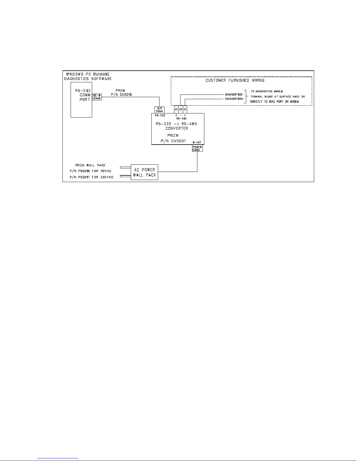
The user s requ red to commun cate w th the M n 4 boards of the system v a RS-485. A
typ cal nstallat on s shown n the follow ng draw ng. Th s deta ls a d agnost c connect on
from a W ndows PC runn ng PMON II to a M n4 board stack.
Moog Components Group 201630-xxx M n 4 Dual Sonar Board Manual, Prel m nary 2/23/09
Page 14 of 14
Figure 1- Typical Cabling/Wiring for Back plane Diagnostics Telemetry
Table of contents


