SALUT
Thank you for purchasing this Xaoc Devices
product. Praga is an expandable
four-channel voltage controlled mixer featur-
ing a stereo mixing bus, two auxiliary sends
with stereo returns, clickless muting, dedicat-
ed modes for unipolar and bipolar voltage
control over volume, DC-coupling, and a su-
per-clean signal path obtained via high-quali-
ty VCA and opamp chips.
control response to achieve what we believe
to be the optimal user experience found in an
eurorack mixer. The design features an elabo-
rate control circuit that combines the internal
voltages generated by the panel potentiom-
eters with external CV over volume and pan
-
sponse that constrains VCA gain to an usable
range while minimizing distortion.
INSTALLATION
The module requires 20hp worth of free
space in the eurorack cabinet. The ribbon
type power cable must be plugged into the
bus board, paying close attention to polar-
ity orientation. The red stripe indicates the
negative 12V rail and should align with the
dot, –12V or red stripe marks on both the
unit and the bus board. The module itself is
protected against reversed power connec-
tion, however reversing the 16-pin header
may cause serious damage to other com-
ponents of your system by short-circuiting
should be fastened by mounting the supplied
screws before powering up. To better under-
stand the device, we strongly advise the user
to read through the entire manual before
using the module.
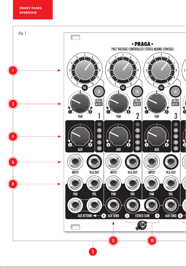
MODULE OVERVIEW
-
sembles a typical mixer with four identical
channels. The vol knobs 1 allow for man-
ual control of each channel's respective lev-
el. Each channel's response depends on the
selected control mode (see: 'Volume Control'
later in this manual). The illuminated ac-
tive|mode button 2 allows the user to mute
the channel or switch between the two control
modes. The pan knob 3 adjusts the channel's
position in the stereo panorama. The bipolar
aux knob 4 adjusts the amount of signal
LED level indicator 5 displays the channel's
post-fader level, while the lower section con-
tains the sockets for signal input 6, direct
vca out 7, CV inputs for pan 8 and vol
control 9. The bottom row of sockets is com-
mon to all four channels and consists of a pair
of stereo sum outputs 10 , two aux send
outputs 11 and two pairs of stereophonic aux
return inputs 12 .
VOLUME CONTROL
Praga offers two modes of combining incom-
ing control voltages with attenuator settings.
The mode is selected individually in each
channel by a long press of the illuminated
active|mode button. Mode switching is
also possible while the channel is muted, con-
2
module
explained