PRO-DESIGN F18E User manual

1
F18E 90mm EDF
High performance Fiberglass F18 for single 90mm electric ducted fan
Specifications are subject to change without notice
Warning !
This model is not a toy and please read the manual carefully before construction and
operating this model aircraft.
Specification
• Flying Weight ~2200g (~4.8 lb)
• Wing span 920mm / 36.2 in.
• Length 1250mm / 49.2 in.
• Rotor diameter 90mm / 3.54 in.

2
Radio system for 4 channels or above
1x Electronic speed controllers for brushless motor
1x 90mm fan-units, EDF shaft adapter diameter 5mm
1x 700-1000W size brushless motors
6-8s Lipo battery for 1600kv brushless motor
4x Servo extension wires
2x Metal gear standard size servo, for elevator
2x 9g servos for ailerons.
5 or 30 minute epoxy, CA Glue
Velcro.
Locktite/ threadlock
Drill , drill bit 2mm, 3mm
Dremel tool
Plier/cutter/ Philip screw driver
2mm , 3mm hex driver
Scissor
Tools needed
Equipment and parts needed
3
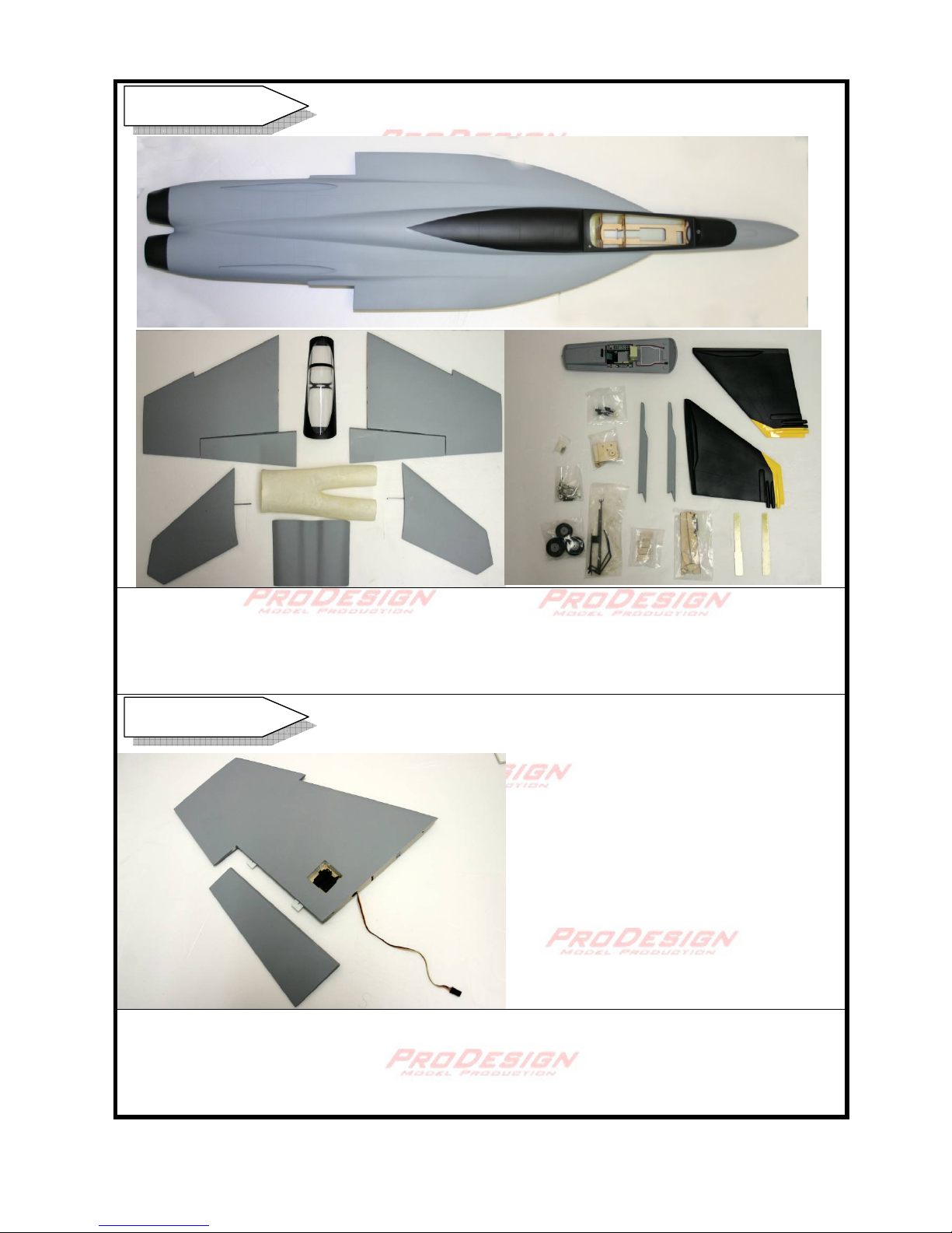
Inside the box : Fuselage, Main wing, Exit ducting, stabilizer, EDF cover, vertical fin, wing
joiner, landing gear and wheel, canopy, cockpit (optional) , hardware bags ( screw, horn,
linkage connector, M3 nut, steering arm, 3mm collar, mounting plate, magnet), Elevator
control hub kit. Waterslide décor. Sidewinder. Pre-painted canopy. Fan unit
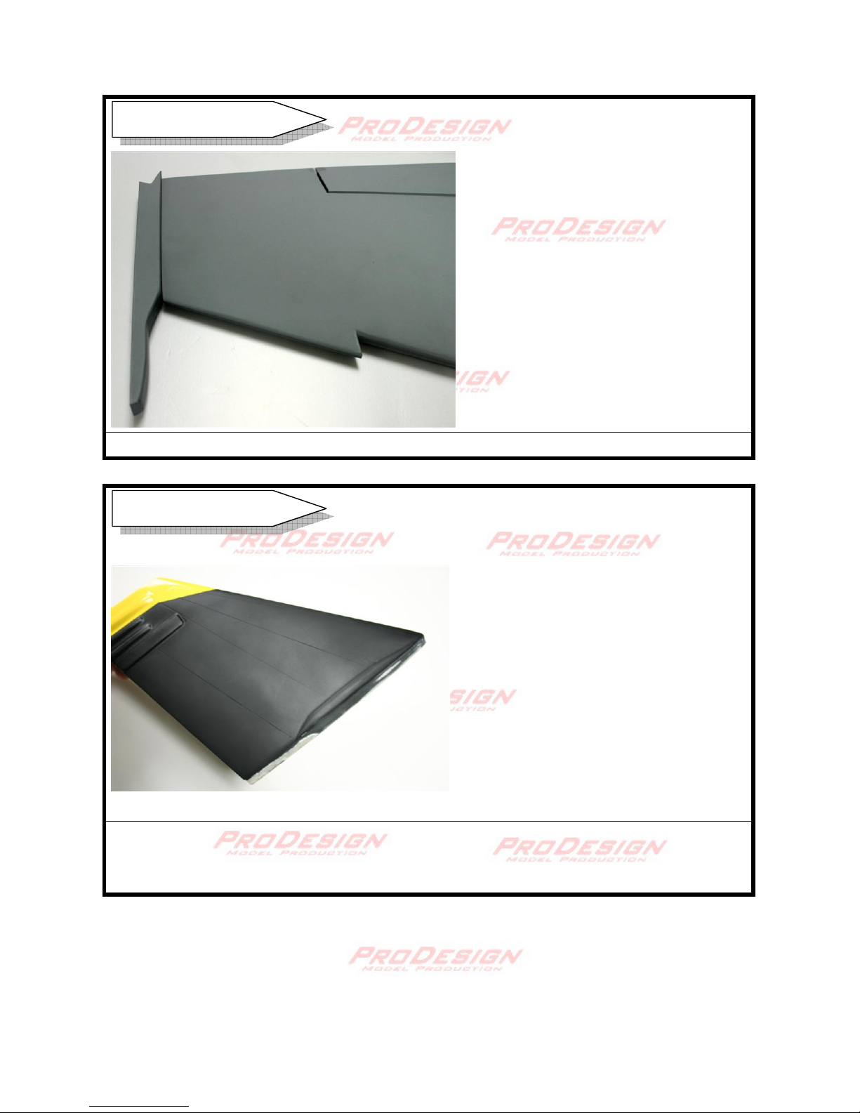
Pay attention the R/L main wings are different. The bottom of each wing is slightly flat in the
airfoil. Remove the aileron control surface. Find a pre-cut slot at the underside of the wing
and cut open the film. Insert the aileron servo and pass the wire through the hole. You may
use servo extension wire.
Inside the Box
Main Wing
4
Do not glue the wing at this point. Try fitting the wings to the fuselage with the wing joiner.
The thinner part of the wing joiner goes into the wing. Adjust and orient the joiner such that
both wings are in perfect position. A 5mm hole can be drilled on the side to pass the wire of
the aileron servos.
The wing joiner is made of fiberglass and this guarantee no risk of wing breakage at high
velocity. Sand the surface of the contact area to maximize bonding strength.
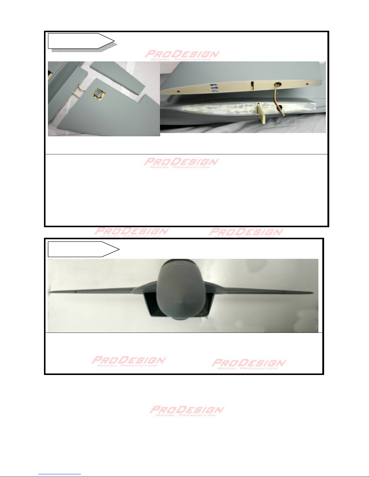
Glue the main wings with epoxy, tape or clamp the wings firmly to the fuselage. Support
the wing with blocks if necessary. Check for horizontal and longitudinal symmetry.
Alignment can be confirmed by putting a pitch meter on top of the wing.
Main Wing
Main Wing
5
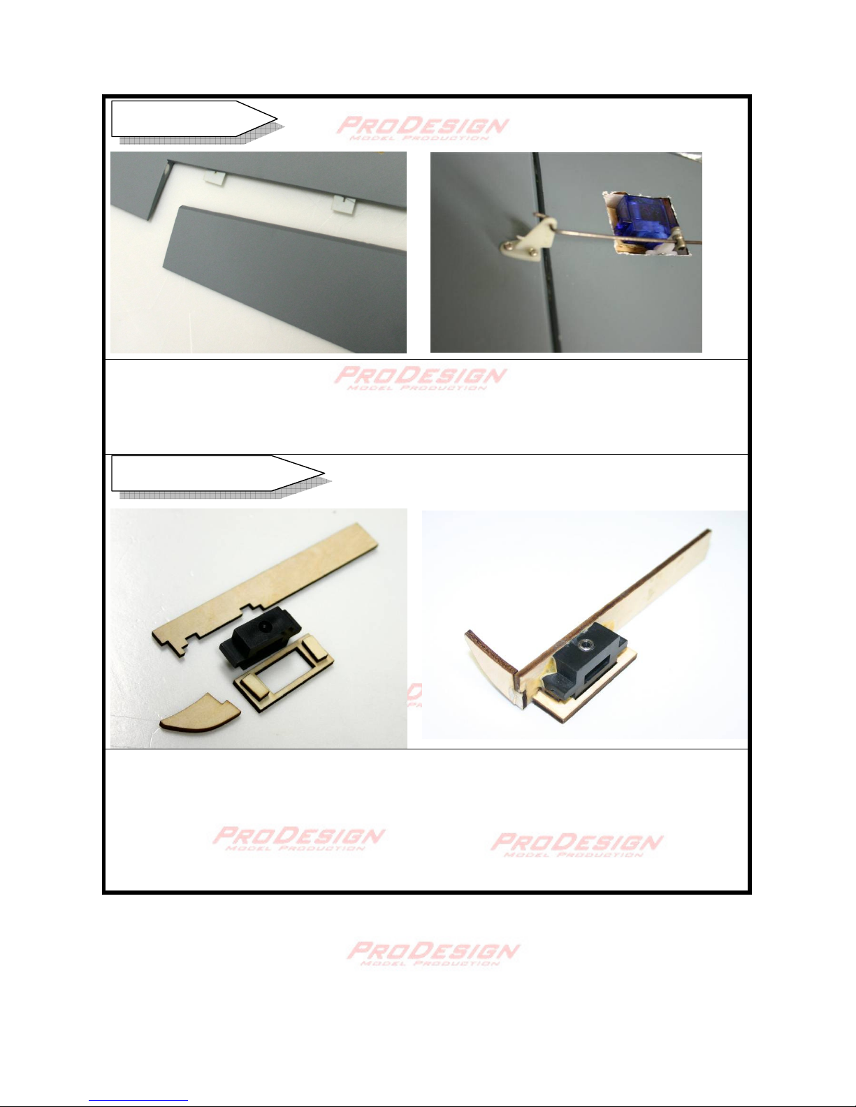
Before gluing the aileron servo, center the servo horn by means of a servo tester or with a
receiver/ transmitter. Install the servo with the balsa wood block provided. Mark the horn
insertion and cut a 5mm slot in the aileron and epoxy the control horn. Use CA to connect
the aileron to the wing. Connect the 9.5cm linkage wire to the servo horn.
The full motion elevator needs attention when assemble. The pro-design kit includes a
special designed bearing hub that renders the elevator movement precise and
maintenance free. Four pieces of 3x6x2.5mm ball bearing is provided. Insert each bearing
into the side of the hub. Very little amount of CA is needed to hold the bearing in place. Be
very careful to spread out a drop of CA inside the hub with a toothpick. Spilling of CA inside
the bearing must be avoided. This shows the right elevator control hub.
Elevator Control Hub
Aileron Servo
6
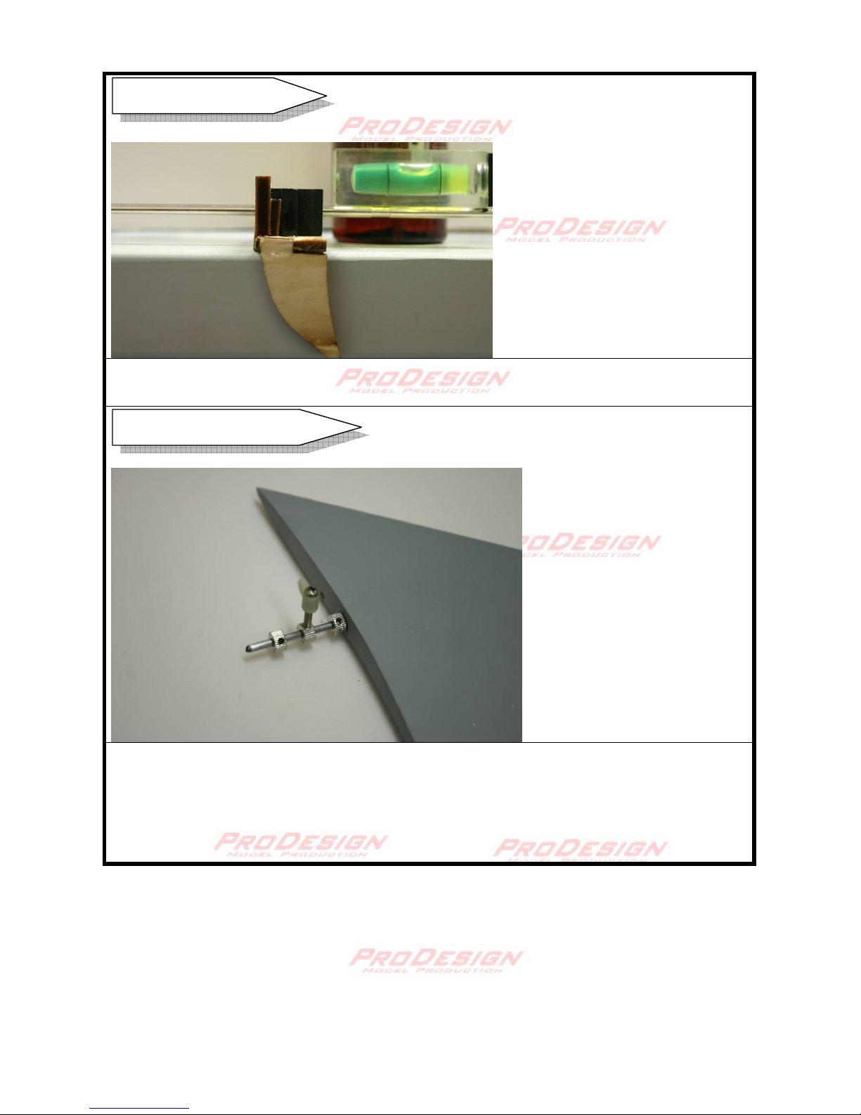
A perfect alignment can be adjusted and measured by inserting a 3mm rod, with a leveler in
place. This is the finish of the left elevator control hub.
Use coarse sandpaper to remove excessive paint on the elevator control rod. Make sure it
can pass through the hub bearing with ease.
Make a slot on the control rod with dremel at a distance ~14.5mm from the base of the
elevator. Try assembling the collar. Make sure the collar with the M3 screw and control horn
can lock the elevator rod without slop.
Elevator Control Hub
Elevator Control Rod

7
Try fitting the elevator into the fuselage and the elevator module. Adjust the best alignment
in different axis. Ensure the elevator have enough clearance from the fuselage. Use a 3mm
collar as a spacer between the elevator and the fuselage. Locktite the collar control arm
through a hole drilled at the fuselage.
Make sure both elevators are in the same level on both sides and with the main wing.
Finally apply epoxy into the module and support the elevator with appropriate blocks and
clamp if necessary. You may first apply small amount of 5 mins epoxy to ensure perfect
alignment. Then apply sufficient 30 min. epoxy.
Elevator
Elevator

8
Connect the 15cm control link to the control arm. Install standard size metal gear servo.
Connect the linkage. Install the linkage connector and center the servo horn.
Cut a hole for wiring of the brushless motor. Cut a 1.5cmx 1cm slot on the side to adapt the
EDF housing. Insertion of the ducting can be made easier with the aid of a long smooth
spatula, or a soft propeller.
Exit Ducting
Elevator Servos

9
Attach double sided adhersive tape around both end of the EDF housing. This is to make a
better seal to enhance the EDF efficiency. Assemble the ducted fan unit and anchor the
ESC.
Check the inflow duct clearance. Test run the EDF and ensure air is blow backward. Check
for any excessive vibration.
Apply sufficient glue so that there is no air leakage.
Drill holes and epoxy the magnets in the canopy and the EDF compartment cover.
EDF cover
Ducted Fan Unit

10
Main landing gear assembly. Connect the wheel collar. Use 2mm screw to connect to the
fuselage retractable gear base. This design allows you to upgrade to retractable gears
without any modification.
Assemble the front gear as shown. Use a 3mm collar at the base. Tighten the steering
control arm. Connect the linkage connector to the steering servo (Rudder Channel)
The height of the front gear is adjusted by the 3mm at the bottom. This is critical for runway
take off. The Wing incidence, the attack angle of the main wing to the runway path, will be
one of the factors for the take off distance. It should be slightly positive when the aircraft is
battery loaded.
Main Landing gear
Front Landing gear
11
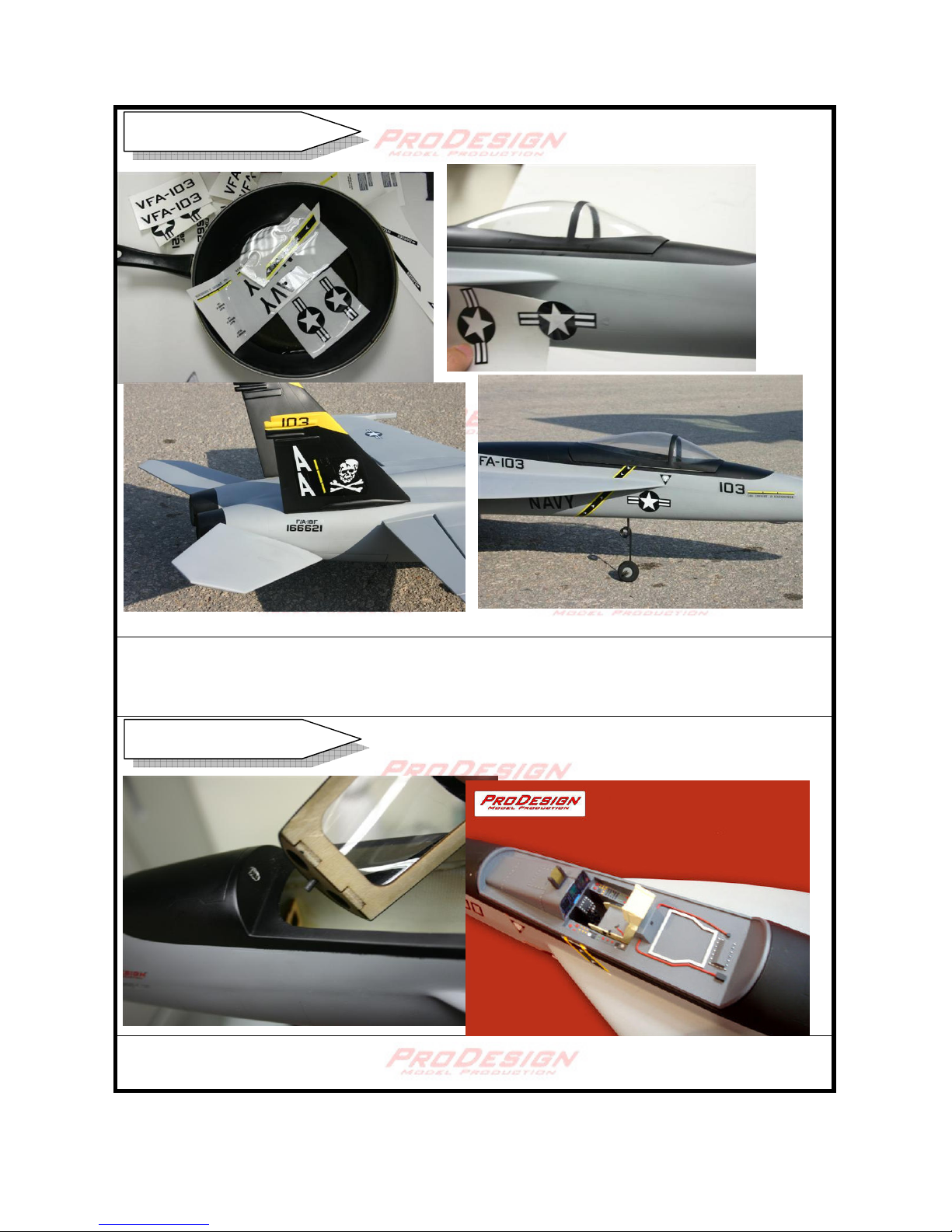
Attach the sidewinder to the side of the wing. Make sure symmetry on both wings.
Trial fit the vertical fin first, you may have to trim 5mm from the front and the back of the
base to get a better fit. Trim with a dremel cutter or saw. Sand the contact areas and apply
epoxy. Install the fin and confirm symmetry on both sides.
Vertical Stabilizer
Sidewinder
12
Realistic water decal is supplied with the ProDesign kit. Cut the water decal into reasonable
pieces and soak in water for 2 seconds. Use a finger and slide the decal in position. Use
tissue paper to remove excessive water.
Drill 4mm hole at front of the cockpit. Glue the magnet to the canopy. Optional realistic
cockpit is also available.
Decals
Cockpit
13
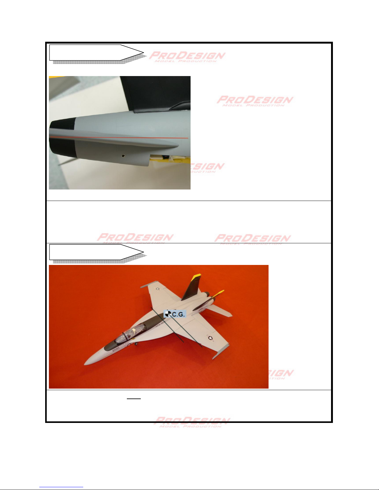
The neutral position of the elevator should be the same horizontal level with main wing.
The above photo shows the down elevator stick/ pitch up at low rate.
Elevator throws 15 mm up 15mm down. Use 50% exponential. Low rate 9mm.
Ailerons throws 13 mm up 13 mm down. Use 30% exponential. Low rate 8mm.
The idea C.G. position is 9cm behind the leading edge measured at where the wing meets
the fuselage. Adjust the battery position to obtain the correct C.G. Check the C.G. before
flying.
C.G. setting
Control Throws
14
Assistance from experienced pilot is necessary for beginners.
Pre-flight adjustment and trimming must be done before flying. Check all
linkage, nuts, servo horns, linkage nuts and screws are tightened. Make sure
thread lockers are applied.
Ensure the flying field is spacious and safe to fly.
Bench test the electronic equipment on loading for 5minutes. Check
temperature of the ESC, BEC and battery. This is to ensure the power
system and the BEC are reliable. All EDF should be run in to test for
vibrations and loosen shaft.
Check all electronic equipment. Range check the radio equipment. Test all
control surface are move in the assigned direction.
Check battery voltage before use, even the battery are recently charged.
At the first flight, it is prudent to check the C.G.
In runway takeoff, slight finger pressure at the trailing edge of the elevator
should be able to pitch up the aircraft.
Enjoy!
Take pictures and video of your scale looking,
high performance ProDesign fighter!
Warning for pilot
This manual suits for next models
1
Table of contents
Other PRO-DESIGN Toy manuals


Popular Toy manuals by other brands


 quick start guide")


Eduard
Eduard Tornado F.3 ADV exterior quick start guide

Techno Gears
Techno Gears Marble Mania HOTSHOT instruction manual

Eduard
Eduard Saipan LVT-2 quick start guide

Mega Bloks
Mega Bloks nickelodeon SpongeBob SquarePants manual

WowWee
WowWee 0442 user manual

Freewing
Freewing Eurofighter Typhoon V2 user manual