PROCONCEPT PLG029 User manual

SAVE THIS MANUAL
You will need this manual for safety instructions, operating procedures, and warranty.
Put it and the original sales invoice in a safe, dry place for future reference.
CONSERVEZ CE GUIDE
Vous aurez besoin de ce guide pour les instructions de sécurité, les procédures d’utilisation et la garantie.
Conservez-le dans un endroit sûr et sec pour référence future.
QUESTIONS? 1 (888) 267-7713
Mon - Fri 7:30 am - 4:30 pm
Canada and United States (except holidays)
Our Customer Service staff are ready to provide assistance. If a part is
damaged or missing, most replacement parts ship from our facility in
two business days.
For immediate help with assembly, or for additional product information,
call our toll-free number: 1 (888) 267-7713.C
Lun - Ven 07h30 à 16h30
Canada et États Unis (sauf les jours fériés)
Notre personnel du Service à la Clientèle seront prêt à fournir
assistance. Si une pièce est endommagée ou manquante, la plupart des
remplacements seront expédiés de notre usine en deux jours ouvrables.
Pour de l’aide immédiate avec l’assemblage, ou pour des informations
additionnelles sur le produit, appeller notre numéro sans frais:
1 (888) 267-7713.C
v.080131
30 cc Gas Brush Cutter
Operator’s Manual (p.2)
Débroussailleuse à gaz de 30 cc
Manuel de l’utilisateur (p.20)
Model / Modèle:PLG029

2 PLG029b
ENGLISH
Throughout this Operator’s Manual and on the product itself, you will nd safety
alerts and helpful informational messages preceded by symbols or key words.
The following is an explanation of these symbols and key words and what they
represent.
This symbol accompanied by the word DANGER! calls attention to an act or
condition which, if not avoided, will lead to death or serious personal injury to the
operator or bystanders.
This symbol accompanied by the word WARNING! calls attention to an act or
condition which, if not avoided, could lead to death or serious personal injury to the
operator or bystanders.
This symbol accompanied by the word IMPORTANT indicates a potentially
hazardous situation which, if not avoided, may result in moderate or minor injury
and provides information necessary for protection of the unit or the operator.
This symbol informs the operator to read the Instruction Manual before operating
this unit.
This symbol reminds the operator to use eye, ear and head protection when
operating power equipment.
This symbol reminds the operator to wear foot protection when operating this
equipment. Beware of foot injuries from the cutting attachment.
TABLE OF CONTENTS
Attachments___________________________________________2
Description of symbols __________________________________2
General Safety Rules ___________________________________3
Additional Rules for Line Trimmer Use ______________________5
Additional Rules for Brush Cutter and Blade Use ______________5
Specications _________________________________________5
Functional Description___________________________________6
Unpacking ____________________________________________6
Assembly_____________________________________________7
Operating Instructions: Fuel ______________________________11
Operating Instructions: Starting and Stopping_________________12
Operating Instructions: Techniques _________________________14
Maintenance __________________________________________15
Troubleshooting________________________________________17
Parts List _____________________________________________18
Schematic Drawing _____________________________________41
ATTACHMENTS
Steel brush-cutter blade
Line trimmer head
Safety guard for metal blade
Safety guard extension for line trimmer
Auxiliary “J” barrier handle
Shoulder strap
n
n
n
n
n
n
DESCRIPTION OF SYMBOLS

v.080131 3
ENGLISH
GENERAL SAFETY INSTRUCTIONS
To use this tool properly, you must observe the safety regulations, the assembly
instructions and the operating instructions to be found in this Manual. All persons
who use and service the machine have to be acquainted with this Manual and must
be informed about its potential hazards. Children should be supervised at all times
if they are in the area in which the tool is being used. It is also imperative that you
observe the accident prevention regulations in force in your area. The same applies
for general rules of occupational health and safety.
WARNING: When using gasoline powered equipment, basic safety precautions,
including the following, should always be followed to reduce the risk of
serious personal injury and / or damage to the unit. Read all these warnings
and instructions before operating this product. Save this Instruction Manual
for future reference.
1. USE THE CORRECT EQUIPMENT FOR THE JOB. Never use this unit for a
purpose for which it was not intended.
2. DRESS CORRECTLY. Wear close tting, tough work clothing that will provide
protection, such as long slack or trousers, safety work shoes and gloves. If you
have long hair, wear a protective hair covering.
3. WEAR PROPER SAFETY EQUIPMENT. Heavy duty work gloves, hard hat, a
safety face shield, or safety glasses for eye protection and a good grade of ear
plugs or other sound barriers for hearing protection should be worn at all times
when operating this unit. The sound level emitted by this equipment can peak at
117Db and it emits 105Db during steady operation.
4. STORE AND OPERATE IN A SAFE PLACE. Open fuel cap slowly to release
any pressure which may have formed in fuel tank. To prevent a re hazard,
move at least 3 metres (10 feet) from fueling area before starting.
5. DO NOT USE ANY OTHER FUEL than that recommended in your manual.
Always follow instructions in the fueling and refueling section of this manual.
Never use gasoline unless it is properly mixed with 2-cycle engine lubricant.
Permanent damage to the engine will result, voiding the manufacturer’s
warranty.
6. DO NOT SMOKE while refueling or operating this equipment.
DESCRIPTION OF SYMBOLS
This symbol reminds the operator to wear gloves when operating this equipment.
Hot surface.
Keep 15 metres (50 feet) away from other people
Beware of thrown objects hit by the cutting attachment. Never use without a properly
mounted guard.
Choke control “Cold Start” position (Choke Closed).
Choke control “Warm Start” position (Choke Open).
Product certied to United States Environmental Protection Agency regulations
50 ft
.
15m

4 PLG029b
ENGLISH
7. NEVER OPERATE THIS UNIT ON THE OPERATOR’S LEFT SIDE
8. AVOID HOT SURFACES. Never operate this unit with the bottom of the engine
above the operator’s waist level.
9. NEVER START OR RUN THE MACHINE INSIDE A CLOSED ROOM OR
BUILDING. Fumes from the exhaust contain dangerous carbon monoxide.
10. KEEP CHILDREN, BYSTANDERS, AND ANIMALS 15 METRES (50 FEET)
AWAY. If approached, stop unit immediately. Operation of gas-powered
equipment should always be restricted to mature and properly instructed
individuals.
11. KEEP ALL PARTS OF YOUR BODY AWAY FROM ANY MOVING PARTS.
12. DO NOT OPERATE UNIT IN AWKWARD POSITIONS. Keep your footing
secure and balanced at all times. Do not overreach.
13. STAY ALERT. Watch what you are doing. Use common sense. Do not operate
power equipment when you are tired or under the inuence of drugs or alcohol.
14. ALWAYS BE AWARE OF YOUR SURROUNDINGS. Stay alert for possible
hazards that you may not hear due to the noise of this unit.
15. CLEAR THE WORK AREA BEFORE EACH USE. Remove all objects such as
rocks, broken glass, nails, wire, or string; which can be thrown or become
entangled in either the blade or the cutting line.
16. KEEP ALL SCREWS AND FASTENERS TIGHT. Never operate equipment
when it is improperly adjusted or not completely and securely assembled.
17. CHECK FOR DAMAGED PARTS. Before further use of the unit, a guard or
other part that is damaged should be carefully checked to determine if it will
operate properly and perform its intended function. Check for alignment of
moving parts, free running of moving parts, breakage of parts, proper mounting
and any other conditions that may affect the operation of the tool. A guard or
other part that is damaged should be properly repaired or replaced by an
authorized service facility, unless otherwise indicated in this Instruction Manual.
18. DEFECTIVE SWITCHES MUST BE REPLACED BY AN AUTHORIZED
SERVICE FACILITY. Do not use power equipment if the switch does not turn
the tool on and off correctly.
19. USE ONLY APPROVED PARTS. When servicing, use only identical
replacement parts. Use an authorized service facility to t replacement parts.
20. STORE EQUIPMENT AWAY FROM POSSIBLE FLAMMABLE MATERIALS,
such as gas-powered water heaters, clothes dryers, or oil-red furnaces,
portable heaters, etc.
WARNING: It has been reported that vibrations from hand-held tools may
contribute to a condition called Raynaud’s Syndrome in certain individuals.
Symptoms may include tingling, numbness and blanching of the ngers,
usually apparent upon exposure to cold. Hereditary factors, exposure to cold
and dampness, diet, smoking and work practices are all thought to contribute
to the development of these symptoms. It is presently unknown what, if any,
vibrations or extent of exposure may contribute to the condition. There are
measures that can be taken by the operator to possibly reduce the effects of
vibration:
nKeep your body warm, especially the head, neck, feet, ankles, hands and
wrists.
nMaintain good blood circulation by performing vigorous arm exercises during
frequent work breaks and also by not smoking.
nLimit the hours of operation. Try to ll each day with jobs where operating the
brush cutter or other hand-held power equipment is not required.
nWear gloves. Gloves help reduce the transmission of machine vibration to your
hands.
IMPORTANT: If you experience discomfort, redness and swelling of the ngers
followed by whitening and loss of feeling, consult your physician before
further exposing yourself to vibration and cold.
IMPORTANT SAFETY INSTRUCTIONS

v.080131 5
ENGLISH
1. After engine stops, allow the blade to keep rotating in thicker weeds or pulpy
stalks until it stops.
2. Do not operate the brush cutter unless the brush cutter guard is rmly secured
in place and in good condition.
3. Use heavy gloves when operating the brush cutter and when installing or
removing blades.
4. Always stop the engine and remove the spark plug wire before attempting to
remove any obstruction caught or jammed in the blade or before removing and
installing the blade.
5. Do not attempt to touch or stop the blade when it is rotating.
6. A coasting blade can cause injury while it continues to spin after the engine is
stopped or throttle trigger released. Maintain proper control until the blade has
completely stopped rotating.
7. Replace any blade that has been damaged. Always make sure blade is installed
correctly and securely fastened before each use. Failure to do so can cause
serious injury.
8. Use only the manufacturer’s replacement blade intended for use on this brush
cutter. Do not use any other blade. Installing any other brand blade or cutting
head to this brush cutter can result in serious personal injury.
9. The blade is suited for cutting thicker weeds or pulpy stalks only. Do not use for
any other purpose.
10. Never use the blade to cut woody brush.
11. Never cut any material over 13 mm (1/2 in.) diameter.
12. Always wear the shoulder harness when using the brush cutter and adjust to
a comfortable operating position. Maintain a rm grip on both handles while
cutting with a blade. Keep the blade away from body and below waist level.
13. Never use the brush cutter with the blade located 75 cm (30 in.) or more above
ground level.
ADDITIONAL SAFETY RULES FOR LINE TRIMMER USE
ADDITIONAL SAFETY RULES FOR BRUSH CUTTER AND BLADE USE
1. Replace line head if cracked, chipped, or damaged in any way. Be sure the line
head is properly installed and securely fastened. Failure to do so can cause
serious injury.
2. Make sure all guards, straps, and handles are properly and securely attached.
3. Use only the correct size replacement line in the cutting head. Do not use any
other cutting attachment. To install any other brand of cutting head to this line
trimmer can result in serious personal injury.
4. Never operate unit without the grass guard in place and in good condition.
5. Maintain a rm grip on both handles while trimming. Keep line head below waist
level. Never cut with the line head located over 75 cm (30 in.) or more above
the ground.
SPECIFICATIONS
Model PLG029b
Dry weight 6.1 kg (13.42 lb.)
Engine Single cylinder 2-stroke engine
Engine displacement 30 cc
Fuel/Oil mix ratio 40:1
Ignition Electronic
Spark plug Torch L8RTC
Engine performance max. 1.0 kW / 7500-8000 rpm
Fuel tank capacity 600 ml (0.16 US gal.)
Drive shaft length 180 cm (71”)
Steel cutter blade 230 mm (9”) diam. x 1.6 mm (1/16”) x 4
teeth
Line trimmer cutting diam. 430 mm (16.9”)
Line diameter 2 mm (0.079”)

6 PLG029b
ENGLISH
FUNCTIONAL DESCRIPTION
A Guard
B Brush cutter blade
C line trimmer head assembly
D Drive shaft housing
EAuxiliary “J” barrier handle
F Forward suspension point
G Ignition switch
H Throttle interlock button
I Main suspension point
J Recoil start handle
K Spark plug connector
L Choke lever
M Primer bulb
N Fuel cap
O Throttle trigger
P Shoulder strap
UNPACKING
WARNING: If any parts are missing, do not operate this tool until the missing
parts are replaced. Failure to do so could result in serious personal injury.
1. Carefully remove the product from the carton.
2. Inspect the product to make sure no breakage or damage occurred during
shipping.
3. Do not discard the packing material until you have inspected and successfully
operated the product.
The Pro-Concept PLG029 Gas Brush Cutter is supplied with the following:
Steel 4-tooth 230 mm (9”) brush cutter blade
Line trimmer head assembly
Safety guard for metal blade
Safety guard extension for line trimmer
Auxiliary “J” barrier handle and clamp assembly
Shoulder strap
Cutter attachment hardware (see g.4):
Spacer sleeve
Blade seat ange
Blade retainer ange
M12 left-threaded hex nut
Nut retention cotter pin
18mm / 20mm socket - phillips screw driver tool
T25 torx driver wrench
5mm hex key
Operator’s manual
n
n
n
n
n
n
n
n
n
n
n

v.080131 7
ENGLISH
ASSEMBLY
Attaching the “J” barrier handle
An auxiliary “J” barrier handle must be used for ensuring the best control and
maximizing operator safety when using a brush cutter. To attach the handle:
1. Place the machine upside-down (with the cutting head facing up) on a horizontal
surface.
2. Attach the cross tube clamp assembly (9-4, g.2) to the shaft housing (D, g.2)
using a 5mm hex key to tighten a clamp plate (9-3, g.2) over the shaft housing
with 2 hex socket head M6 x 16 bolts.
3. Turn the machine right side up.
4. Using a 5mm hex key turning 2 hex socket head M6 x 16 bolts, tighten the other
clamp plate over the J-handle onto the cross tube casting.
5. After assembly is complete, adjust the position of the handle for best balance
and comfort.
Attaching the Brush Cutter Guard
1. Remove the cutter attachment hardware (g.4) from the cutter head:
U. Nut retention cotter pin
T. M12 left-threaded hex nut- (turns clockwise to remove)
S. Blade retainer ange
R. Blade seat ange
Q. Spacer sleeve
Remove also from the gear head: 3 M6 x 15 torx/slot pan head screws
8 PLG029b
ENGLISH
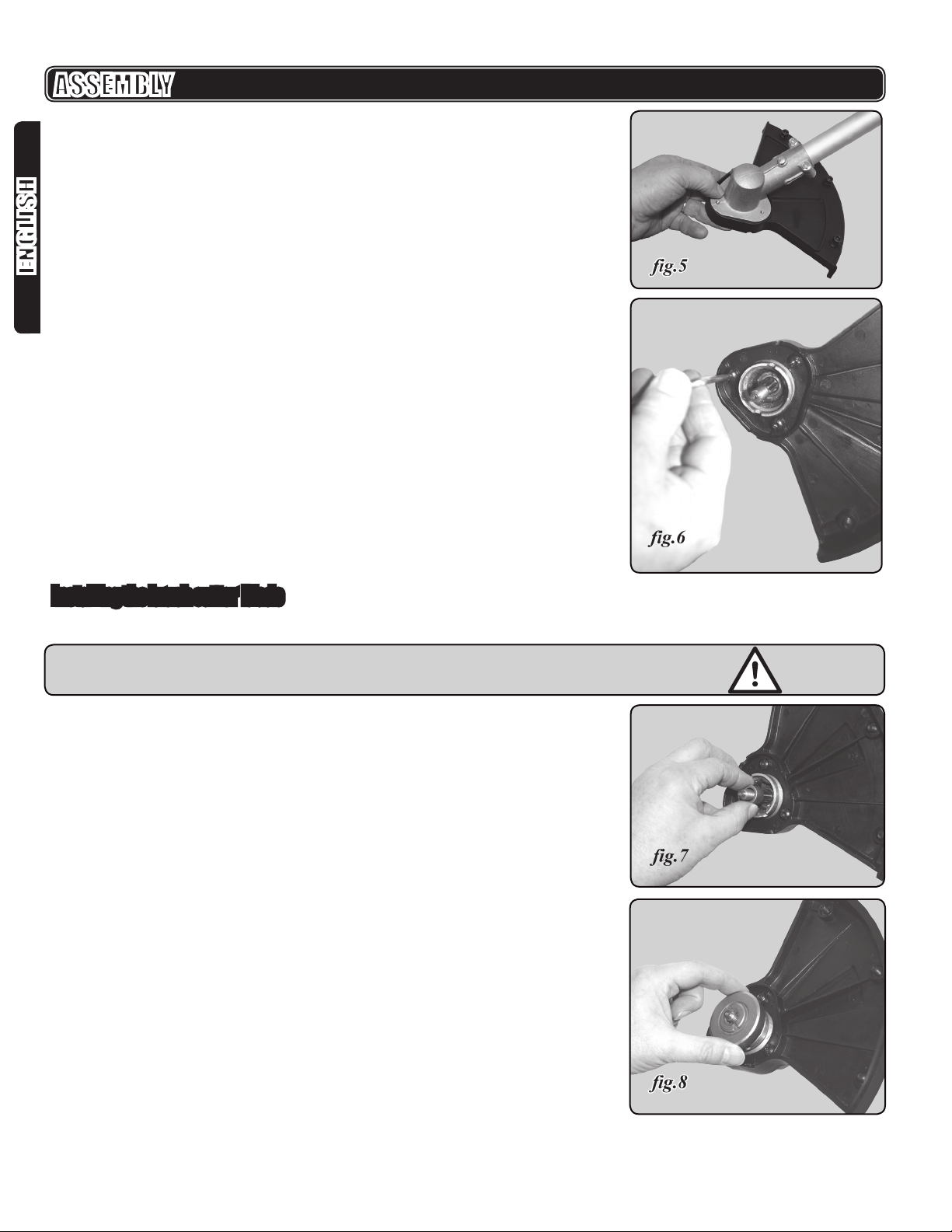
2. With the line head or steel blade removed, place the brush cutter guard on the
gear head as shown in g.5.
3. Using the included T25 torx driver wrench or a slot screwdriver, re-install the
three M6 x 15 torx/slot pan head screws from bottom through the guard and
into the gear head (g.6).
4. Tighten the screws securely.
Installing the brush cutter blade
1. Be sure the safety guard for the brush cutter blade is properly installed.
WARNING! Do not install the brush cutter blade without rst attaching the guard.
2. Place the machine upside-down (with the cutting head facing up) on a horizontal
surface.
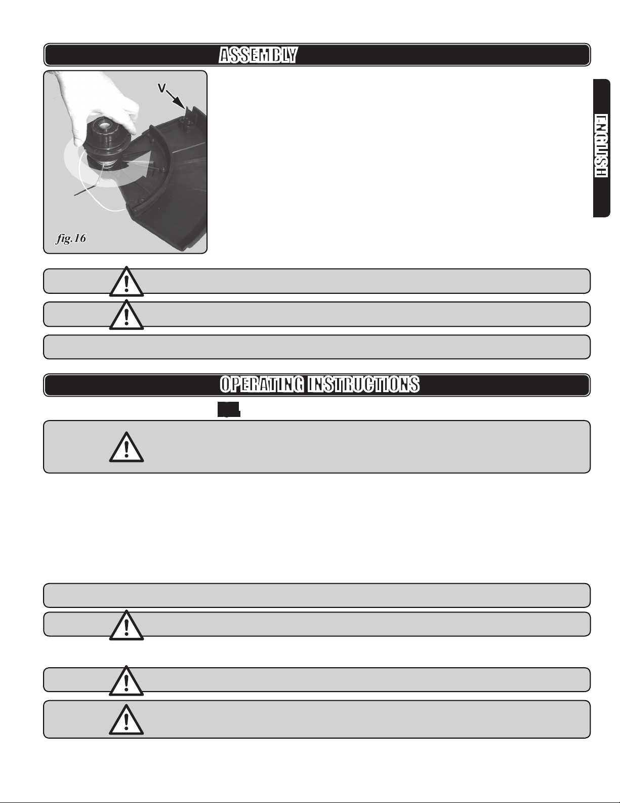
3. Place the spacer sleeve (Q, g. 4) over the gear head shaft (g.7).
4. Place the blade seat ange (R, g. 4) over the gear head shaft (g.8), aligning
grooves in the ange with the splines on the shaft.
ASSEMBLY

v.080131 9
ENGLISH
5. Center the blade on the blade seat ange, making sure the blade ts at and the
raised hub of the ange goes through the hole in the blade. It is a good idea to
have the printed side of the blade facing up towards the operator as the white
printing makes the blade more visible while turning.
6. Place the blade retainer ange (S, g. 4) over the shaft with the raised centre
boss away from the blade and its 2 pins going down through the blade to
engage the matching dimples in the top surface of the blade seat ange (g. 9 &
10).
7. Place the M12 left-threaded hex blade nut (T, g.4) onto the gear head shaft
(g.11). Turn it counter-clockwise to tighten.
8. Align the hole in the blade seat ange with the hole in the gear head.
9. Insert the T25 torx driver wrench as a gear head locking tool through the slot in
the blade seat ange and gear head (g.12).
ASSEMBLY

10 PLG029b
ENGLISH
10. Install the blade nut by turning it counter-clockwise (left handed threads).
11. Tighten the blade nut securely and torque to 13.55 Nm (120 in/lbs) minimum:
nger tight plus 1/2 turn with the 18mm / 20mm socket - phillips screw driver
tool (g.13).
12. Insert the nut retention cotter pin (U, g.4) through the shaft and bend the ends
ASSEMBLY
Attaching the Shoulder Harness
1. Connect the snap hook on the shoulder harness to the strap hanger at either
the forward suspension point (F, g.1) or the main suspension point (I, g.1),
whichever balances the machine more easily.
2. Adjust the strap to a comfortable position.
NOTE: In case of an emergency, push the release on the snap hook and remove
the harness from the machine
Converting from Brush Cutter to Line Trimmer
To convert from the brush cutter to the line trimmer:
1. Remove the nut retention cotter pin (U, g.4).
2. Remove M12 left-threaded hex blade nut (T, g.4) by turning it clockwise.
3. Remove the blade retainer ange (S, g. 4).
4. Remove the brush cutter blade.
5. Using the 5mm hex key, remove the 3 hex socket head bolts and lock washers
in the brush cutter guard.
6. Attach the safety guard extension for line trimmer to the brush cutter guard with
the 3 hex socket head bolts and lockwashers. (g.15).
v.080131 11
ENGLISH
ASSEMBLY
7. Align the hole in the blade seat ange with the hole in the gear head.
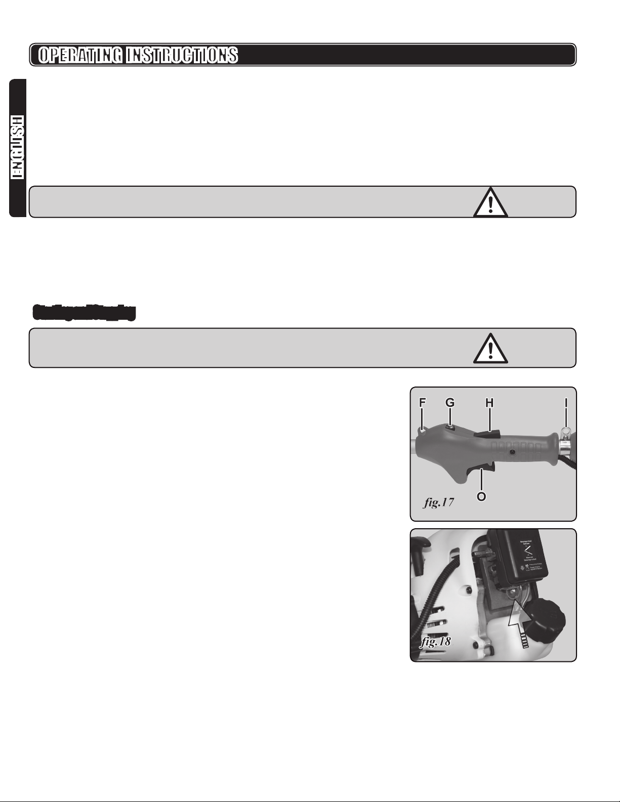
8. (g.16) Insert the T25 torx driver wrench as a gear head locking tool through the
slot in the blade seat ange and gear head.
9. Thread on the line trimmer head. It is left-threaded and screws on
counterclockwise.
10. Tighten the line trimmer head well.
11. Check that the line cutting blade (V, g.16)does not have its shipping cover over
it.
WARNING! Do not install the line trimmer head without rst attaching the safety
guard extension for line trimmer
WARNING! The line cutting blade on the guard is sharp. Avoid contact with the
blade. Failure to avoid contact can result in serious personal injury.
NOTE: Store the remaining brush cutter parts; the blade, blade retainer ange, nut,
and cotter pin together for later use.
OPERATING INSTRUCTIONS
FUEL
IMPORTANT: Never use straight gasoline in your unit. This will cause permanent
engine damage and void the manufacture’s warranty for that product. Use
regular grade unleaded gasoline mixed with 2-cycle engine oil in 40:1 ratio for
best results. Never use a fuel mixture that has been stored for over 60 days.
GASOLINE - The lowest recommended octane rating is 87. If you run the engine
on gasoline with a lower octane rating than 87 so-called “knocking” can occur.
This leads to an increased engine temperature which can result in serious engine
breakdown.
TWO-STROKE OIL -You must use premium grade 100% synthetic oil intended for
heavily stressed two-stroke engines mixed at a 40:1 ratio, intended for air cooled
engines. Do not use any 2-cycle oil product with a recommended mixing ratio of
100:1. If needed, contact your dealer when selecting oil.
REMEMBER: Mixing ratio: 40:1
IMPORTANT: Never use two-stroke oil intended for water cooled outboard engines
or four-stroke engines.
MIXING FUEL
WARNING: Fuel is VERY ammable. Use extreme caution when mixing, storing or
handling fuel or serious personal injury could result.
WARNING: Always mix and store the fuel in a properly marked container that is
approved by local codes and ordinances for such usage. Do not mix fuel in an
enclosed room or near open ames. Assure adequate ventilation.
12 PLG029b
ENGLISH
OPERATING INSTRUCTIONS
1. Start by lling half the quantity of gasoline required into a clean approved petrol
container.
2. Add the entire oil quantity.
3. Close container and mix (shake) the fuel mixture.
4. Add the remaining quantity of gasoline.
5. Remix (shake) the fuel mixture carefully before lling the unit’s fuel tank.
6. Replace fuel container cap and wipe any spilled fuel from the container and
surrounding area.
FILLING TANK
WARNING: Always shut off engine before fueling. Never add fuel to a machine
with a running or hot engine.
1. Clean surface around fuel cap to prevent contamination.
2. Loosen fuel cap slowly. Rest the cap on a clean surface.
3. Carefully pour fuel into the fuel tank. Do not ll fuel tank more than 80% of tank
capacity.
4. Prior to replacing the fuel cap, clean and inspect the gasket.
5. Immediately replace fuel cap and hand tighten. Wipe up any fuel spillage
Starting and Stopping
WARNING!
Move at least 9 m (30 ft.) from refueling site before starting engine.
Do not smoke! Do not allow open ame near the brush cutter or fuel.
Trimmer should be on a at, bare surface for starting.
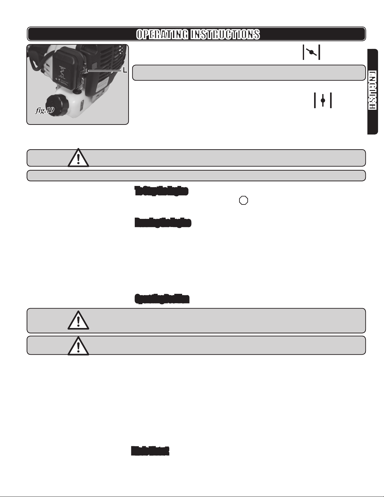
1. Set the ignition switch (G, g.17) to “I”: START.
2. Slowly press the primer bulb 6 - 8 times (g.18), until the gas/oil mixture ows in
and out of the discharge hose above the fuel tank..
n
n
v.080131 13
ENGLISH
OPERATING INSTRUCTIONS
3. Move the choke lever (L, g.19) up to choke or cold start: .
NOTE: This is not required if the engine is already warm.
4. Pull the recoil start handle 2 or 3 times quickly until engine attempts to run.
5. Move the choke lever down to the run or warm start position: .
6. Pull the starter grip until engine runs.
7. Allow engine to run at idle for about 10 seconds to warm up.
8. To speed up the motor so it engages the clutch and turns the cutter, press and
hold the throttle interlock button (H, g.1 & 17) while squeezing the throttle
trigger (O, g.1 & 17).
IMPORTANT: The blade should not turn when the motor is running at idle. If it
does, even a little, see Maintenance, p.17.
NOTE: It is normal for smoke to be emitted from a new engine after rst use.
To Stop the Engine
Move the ignition switch (G, g.17) to “
STOP
”: the STOP position.
Running the Engine
After 2 hours, stop and check that all nuts and screws remain securely fastened.
Tighten if necessary.
During the rst 10 hours of work, run the engine only at a moderate speed.
Do not run the engine at high speed during this period so that the different
components can wear in gradually and without damage.
At the end of the break-in period, the motor will be able to achieve maximum
power.
Prolonged cutting at partial throttle will result in oil dripping from the mufer.
Operating Position
WARNING: Always position the unit on the operator’s right side. Using the unit on
the operator’s left side will expose the user to hot surfaces and can result in a
possible burn injury.
WARNING: To avoid burns from hot surfaces, never operate unit with the bottom of
the engine above waist level.
1. Hold the trimmer with the right hand on the rear control handle and the left hand
on the auxiliary “J” barrier handle. Keep a rm grip with both hands while in
operation.
2. Hang the trimmer from the shoulder by the strap, Adjust the shoulder harness to
position the brush cutter at a comfortable operating position and to assure that
the shoulder harness will reduce the risk of operator contact with the blade and
with the control handle about hip height.
3. Maintain your grip and balance on both feet.
4. Position yourself so that you will not be drawn off balance by the blade thrust or
kickback reaction of the cutting blade.
5. Cut from right to left.
Blade Thrust
Exercise extreme caution when using the brush cutter blade with this unit. Blade
thrust is the reaction that may occur when the spinning blade contacts anything it
n
n
n
n
n

14 PLG029b
ENGLISH
cannot cut. This contact may cause the blade to stop for an instant, and suddenly
thrust the unit away from the object that was hit, or kickback. This reaction can be
violent enough to cause the operator to lose control of the unit. Blade thrust can
occur without warning if the blade snags, stalls, or binds. This is more likely to
occur in areas where it is difcult to see the material being cut. For cutting ease
and safety, approach the weeds being cut with the brush cutter, from the right to the
left. In the event an unexpected object or woody stock is encountered, this practice
could minimize the blade thrust reaction.
WARNING: To avoid burns from hot surfaces, never operate unit with the bottom
of the engine above waist level.
IMPORTANT: Clear the work area before each use. Remove all objects such as
rocks, broken glass, nails, wire, or string which can be thrown or become
entangled in the cutting line or blade.
Blade
The blade is suited only for thicker weeds and pulpy stalks. When the blade
becomes dull, it can be turned over to extend its life.
Cutting Technique – Blade:
WARNING: Extreme care must be taken when using blades to ensure safe
operation. For safe operation using the blade, refer to “Additional Safety Rules
for Brush Cutter / Trimmer Use” earlier in this manual.
Always hold brush cutter on your right side with both hands when operating.
Use a rm grip on both handles.
Maintain your grip and balance on both feet. Position yourself so that you will
not be drawn off balance by the kickback reaction of the cutting blade.
Inspect and clear the area of any hidden objects such as glass, rocks, concrete,
fencing, wire, wood, metal, etc.
Never use blades near sidewalks, fencing, posts, buildings or other immovable
objects.
Never use a blade after hitting a hard object without rst inspecting it for
damage. Do not use if any damage is detected.
The unit is used as a scythe, cutting from the right to the left in a broad
sweeping action from side to side.
Use only the supplied blade. To install any other brand blade or cutting head to
this brush cutter can result in serious personal injury.
Line Trimmer Head
Use the line trimmer head for cutting grass along borders or near sidewalks,
fencing, posts, buildings or other immovable objects, where using a blade would
be dangerous.
Cutting Technique– Line Trimmer Head
Keep the trimmer tilted toward the area being cut; this is the best cutting area.
Use the tip of line to do the cutting; do not force line head into uncut grass.
Wire and picket fences cause extra line wear, even breakage. Stone and brick
walls, curbs, and wood may wear line rapidly.
Avoid trees and shrubs. Tree bark, wood moldings, siding, and fence posts can
easily be damaged by the line.
To Advance the Cutting Line
Line advance is controlled by “Bumping” the line head on grass while running
engine at full throttle.
1. Run engine at full throttle.
2. “Bump” the spool retainer on ground to advance line. The line advances each
time the spool retainer is bumped. Do not hold the spool retainer on the ground.
n
n
n
n
n
n
n
n
n
n
n
OPERATING INSTRUCTIONS
v.080131 15
ENGLISH
OPERATING INSTRUCTIONS
NOTE: The line trimming cut-off blade on the grass guard will cut the line to the
correct length.
IMPORTANT: If the line is worn too short you may not be able to advance the line
by tapping it on the ground. If so, STOP the engine, and manually advance the
line.
To advance the cutting line manually, push the spool retainer down while pulling on
line(s) to manually advance the line.
The trimmer is equipped with a line trimming cut-off blade on the grass guard.
For best cutting, advance line until it is trimmed to length by the cut-off blade.
Advance the line whenever you hear the engine running faster than normal, or
when trimming efciency diminishes.
This will maintain best performance and keep the line long enough to advance
properly.
WARNING! If grass becomes wrapped around the line head or blade,
STOP THE ENGINE, disconnect the spark plug wire, and remove the grass.
n
n
n
n
MAINTENANCE
WARNING: Use only original manufacturer’s replacement parts, accessories and
attachments. Failure to do so can cause poor performance, possible injury
and may void your warranty.
You can often make adjustments and repairs described here. For other repairs,
have the trimmer serviced by an authorized service dealer.
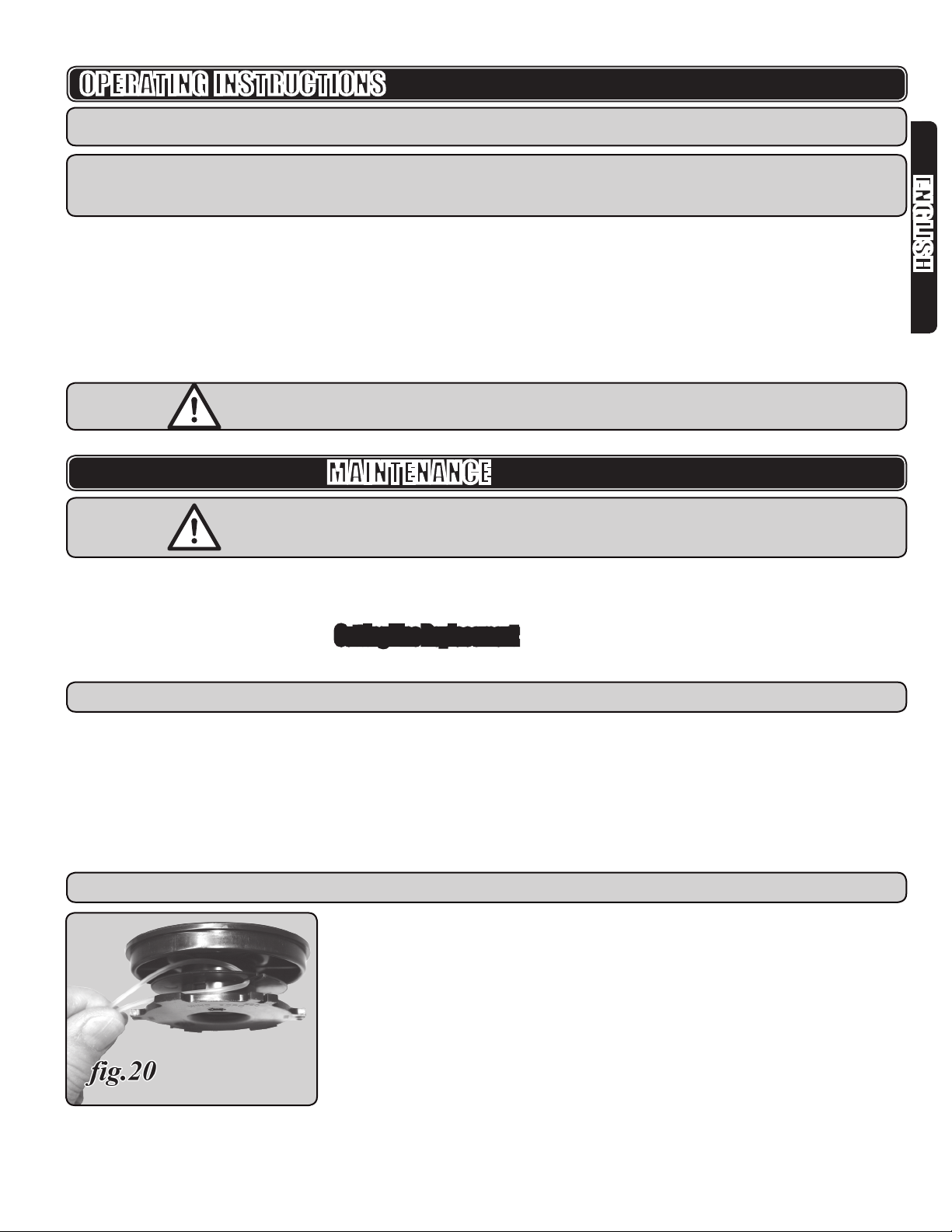
Cutting Line Replacement
Use only monolament line.
IMPORTANT: Line Diameter: 2.0 mm (0.082”)
1. Switch off the ignition switch to stop the engine.
2. Disconnect the spark plug wire.
3. Insert the T25 torx driver wrench as a gear head locking tool through the slot in
the blade seat ange and gear head.
4. Remove the line trimmer head assembly, turning it clockwise.
5. Hold the line head and unscrew the spool retainer (19, g.22), turning it
counterclockwise.
6. Remove the spool (18-5, g.22) from the line head.
NOTE: Keep the spring attached to the spool.
7. Remove any old line remaining on the spool.
8. Cut a piece of line, approximately 5.5 m (18 ft.) long.
9. Fold the line in half.
10. Insert the line into the slot in the spool (g.20) at the fold.
11. Wind the line around the 2 slots of the upper/bottom spool anges, following the
“Wind Cord” arrows on the spool. Do not overll.

16 PLG029b
ENGLISH
MAINTENANCE
12. Leave about 15 cm (6”) extended and put these ends through two of the slots
on the lower rim of the spool.
13. Run the two line ends through the grommets in the trimmer head casing (g.21).
14. Replace the spool and spring into the trimmer head casing.
15. Use the spool retainer (19, g.22) to screw counter-clockwise through the spool
(18-5, g.22), the spring (18-4, g.22) and the trimmer head casing (18-3,
g.22) into the trimmer shaft (17, g.22).
16. Follow steps 7 & 8 and g.16 in Assembly, p.11 to re-install the reloaded
trimmer head assembly
Adjusting the Idle
If the blade or trimmer head turns even a little when the motor is running at idle:
Adjust the idle screw (W, g.23) on the throttle linkage above the carburetor.
Access it through a hole in the back cover (in the direction of the line from the
right, g.23).
Replacing and Cleaning Air Filter
For proper performance and long life, keep air lter clean.
1. Remove the air lter cover by pressing in the sides and lifting it off.
2. Remove lter and tap it to remove the dust
3. Heavy dirt deposits should be washed out with a suitable solvent. Let dry
completely.
4. Reinstall the lter.
5. Replace the air lter cover.
Spark Plug
1. Check the spark plug every 10 - 15 hours of operation.
2. Remove the spark plug cap.
3. Use the provided wrench to remove the spark plug.
4. Clean and adjust the spark plug gap to 0.6 - 0.7 mm
5. Replace any damaged or visibly worn plug with a Torch L8RTC or equivalent
spark plug.
Storage (1 Month or Longer)
Drain all fuel from tank into a container approved for gasoline.
Run engine until it stops.
Add a few drops of oil through the spark plug hole.
Turn the engine a couple of pulls of the starter so all the internal parts are
coated.
Replace the spark plug.
Clean all foreign material from the trimmer.
Store it off the oor, hanging by the main suspension point in a well-ventilated
place, inaccessible to children.
Keep away from corrosive agents such as garden chemicals and de-icing salts.
Abide by all ISO and local regulations for the safe storage and handling of
gasoline. Excess fuel should be used up in other 2-cycle engine powered
equipment.
n
n
n
n
n
n
n
n
n
n

v.080131 17
ENGLISH
Cleaning the Exhaust Port and Mufer
Depending on the type of fuel used, the type and amount of oil used, and/or your
operating conditions, the exhaust port and mufer may become blocked with carbon
deposits. If you notice a power loss with your gas powered tool, a qualied service
technician will need to remove these deposits to restore performance.
MAINTENANCE
TROUBLESHOOTING
PROBLEM CAUSE SOLUTION
Engine not starting Empty tank Fill with mixed fuel
Flooded engine Close the throttle, start several times.
Take out the spark plug and dry if needed
Dirty spark plug (carbon deposit on
electrodes), electrode gap is too large
Clean spark plug, check its temperature, replace if needed
Adjust gap to 0.6 to 0.7 mm
Dirty carburetor or jets Clean carburetor with air
Damaged spark plug or spark plug
connection
Replace
No spark Check for short in spark plug lead, ignition module
Replace if necessary
Reduce spark plug gap to 0.3 to 0.4 mm
Engine runs too fast at idle Cold engine Warm up slowly or close the choke a bit
Idle set too high Adjust idle screw
Engine does not reach max capacity Dirty spark plug (carbon deposit on
electrodes), electrode gap is too large
Clean spark plug, check its temperature, replace if needed
Dirty carburetor or jets Clean carburetor with air
Dirty air lter Clean
Dirty exhaust or exhaust channel Take out and clean
Sealing ring in crankcase not seated properly Replace
Worn cylinder, piston, or piston rings Replace or reface the cylinder and piston assembly
Poor fuel mix (too much oil) Empty tank and remix & ll correctly
Bad ignition Adjust the ignition module lever (0.3 -0.4 mm)
Engine power loss or sudden stop Empty tank Fill with mixed fuel
Fuel mix does not reach the carburetor Clean the fuel lter in the tank
Water in fuel Drain and rinse the fuel system
Dirty air lter Clean
Carbon deposits in cylinder exhaust pipe or
mufer
Clean both and/or replace mufer
Engine does not stop Spark plug is light grey with signs of heating
(heat drops)
Install a spark plug with a higher thermal value
Remains of carbon in the combustion area Clean cylinder head, piston bottom, & cylinder channels
Poor quality cut Cutter overloaded due to too high grass or
too thick brush
Cut grass from top down
Not enough power for thickness of brush
If your tool requires service, ask your retailer or us at 1-888-267-7713 for an
authorized repair centre in your area.
IMPORTANT: If these solutions do not solve the problem contact your authorized
service facility.

18 PLG029b
ENGLISH
PARTS LIST
Please refer to the schematic Drawing, p. 41.
ITEM No. DESCRIPTION
1-1 Screw M5 x 25
1-2 Phillips head bolt M5 x 20
1-3 Clutch cover
1-4 Coach nut M5
1-5 Crosshead bolt M5 x 23
1-6 Front cover
1-7 Recoil start hand grip
1-8 Spacer
1-9 Heat shield
1-10 Recoil start spring
1-11 Spring seat
1-12 Recoil pulley
1-13 Start rope
1-14 Start retainer
1-15 Screw M4 x 12
1-16 Back cover
1-17 Screw M5 x 16
1-18 Start spring assy.
1-19 Front cover assy.
2-1 Clutch disc
2-2 Clutch driver
2-3 Tube
2-4 Washer 10
2-5 Flywheel assy.
2-6 Bolt M5 x 23
2-7 Ignition apparatus
2-8 Wiring assy.
2-9 Spark plug
3-1 Cylinder
3-2 Cylinder gasket
3-3 Piston ring
3-4 Piston
3-5 Wrist pin
3-6 Wrist pin retainer
3-7 Needle bearing, 8 x 12 x 10
3-8 Connecting rod
3-9 Needle bearing, 9.5 x 14.3
3-10 Piston & rod assy.
4-1 Crank case
4-2 Ball bearing 6001LLU
4-3 Oil seal TC28 x 12 x 7
4-4 Ball bearing 6201
4-5 Bolt M6 x 20
4-6 Crankshaft assy.
ITEM No. DESCRIPTION
4-7 Crank case gasket
4-8 Crank case cover
4-9 Bolt M5 x 15
4-10 Crank case assy.
5-1 Fuel tank cushion
5-2 Fuel line
5-3 Fuel line seat
5-4 Fuel lter
5-5 Fuel tank
5-6 Fuel cap ring
5-7 Fuel cap gasket
5-8 Valve seat
5-9 Air/oil valve
5-10 Air/oil lter
5-11 Fuel cap
5-12 Intake gasket
5-13 Bolt M5 x 68
5-14 Carburetor seat
5-15 Carburetor gasket
5-16 Air lter spacer
5-17 Carburetor
5-18 Air lter body
5-19 Choke lever
5-20 5mm washer
5-21 Nut M5
5-22 Choke spring
5-23 Washer 5mm x 13.5mm
5-24 Sponge
5-25 Air lter cover
5-26 Air lter assy.
5-27 Fuel tank assy.
5-28 Fuel cap assy.
6-1 Exhaust gasket
6-2 Mufer
6-3 Mufer cover
6-4 Exhaust bracket
6-5 Bolt M5 x 53
7-1 Control handle, left
7-2 Ignition switch
7-3 Phillips head bolt, M5 x 10
7-4 Tapping screw st 2.9 x 12
7-5 Tapping screw st 2.9 x 12
7-6 Interlock block
7-7 Interlock spring

v.080131 19
ENGLISH
ITEM No. DESCRIPTION
7-8 Interlock lever
7-9 Throttle trigger spring
7-10 Throttle trigger
7-11 Control handle, right
7-12 Tapping screw st 3.5 x 15
7-13 Wire loom
7-14 Throttle cable
7-15 Control handle assy.
8-1 Tapping screw M5 x 13
8-2 Shaft sleeve
8-3 Drive shaft
8-4 Drive shaft housing assy.
9-1 Auxiliary handle assy.
9-2 Hex socket head bolt, M6 x 16
9-3 Clamp plate
9-4 Cross tube clamp casting
9-5 J handle assy.
10 Gear housing assy.
11-1 Inner safety guard for metal blade
11-2 M6 x 15 torx/slot pan head screw
11-3 Outer safety guard extension for trimmer
11-4 Hex socket head bolt, M6 x 20
11-5 Line cut-off blade
11-6 Nut M5
11-7 Screw M5 x 16
11-8 Expansion washer 5
PARTS LIST
Please refer to the schematic Drawing, p. 41.
ITEM No. DESCRIPTION
11-9 Washer 5
11-10 Outer guard assy.
12 Spacer sleeve
13 Blade seat ange
14 230mm brush cutter blade
15 Blade retainer ange
16 M12 left-threaded hex nut
17 Trimmer shaft
18 Line trimmer head assy.
18-1 Trimmer head ring
18-2 Grommet
18-3 Trimmer head casing
18-4 Spring
18-5 Line spool
18-6 Trimmer line
19 Spool retainer assy.
19-1 Knob
19-2 Captive bolt
19-3 Washer
19-4 Metal cap
20-1 Socket/driver wrench
20-2 T25 torx wrench
20-3 5mm hex key
20-4 Shoulder strap
21 Cotter pin
All products distributed by Airco Superior Clarke are warranted against
manufacturers’ faults and defects for a period of one year from the date of purchase
by the end user. The Company will REPAIR OR REPLACE, AT ITS OWN OPTION,
merchandise deemed by the company to be defective, provided that is has not
been misused, abused, altered, or repaired by anyone other than an authorized
repair centre. Retain proof of purchase. Return the defective product to the place of
purchase.
This warranty does not extend to parts deemed consumables, such as brad and
staple gun driver blades, grinding discs, welding contact tips, etc. All warranty claims
must have prior authorization and must be shipped prepaid to the Richmond, BC
or Mississauga, ON warehouses, or an authorized repair depot, accompanied by a
copy of the invoice specifying the date that the item was sold to the end user. You
should take any tool with a problem back to where you purchased it, accompanied
by your receipt.
WARRANTY
WARNING: Repairs should be made by an authorized repair centre. Opening this
tool could invalidate your warranty.
IMPORTANT: Our products are continually monitored to comply with changing
technical standards and requirements. The company reserves the right to
alter design and specications without prior notice.

20 PLG029b
FRANÇAIS
Ce mode d’emploi et de produit contient des alertes en matière de sécurité ainsi
que des messages utiles et informatifs précédés de symboles ou de mots-clés.
Voici l’explication de ces symboles et mots-clés et de ce qu’ils représentent.
Ce symbole, accompagné du mot DANGER! attire votre attention sur un geste ou
une condition qui mènera à la mort ou aux blessures sérieuses l’utilisateur ou aux
observateurs.
Ce symbole, accompagné du mot AVERTISSEMENT attire votre attention sur un
geste ou une condition pouvant entraîner des blessures sérieuses à l’utilisateur ou
aux observateurs.
Ce symbole, accompagné du mot IMPORTANT, attire votre attention sur un
geste ou une condition pouvant entraîner des blessures modérés ou mineurs à
l’utilisateur ou aux observateurs et offre l’information nécessaire à la protection de
l’appareil ou de l’opérateur.
Ce symbole informe l’opérateur qu’il doit lire le manuel d’instructions avant
d’utiliser l’appareil.
Ce symbole rappelle à l’opérateur de porter des protecteurs oculaires, auditifs et
de tête lorsqu’il utilise cet outil.
Ce symbole rappelle à l’opérateur de porter des chaussures de sécurité lorsqu’il
utilise cet outil. Prenez garde des blessures aux pieds par tête de coupe.
TABLE DES MATIÈRES
Accessoires ___________________________________________20
Description des symboles ________________________________20
Importantes directives de sécurité__________________________21
Régles de sécurité additionelles pour l’utilisation du taille-bordure_23
Règles de sécurité additionnelles pour débroussailleuse
et utilisation de sa lame _______________________________23
Spécications _________________________________________24
Liste des composantes __________________________________25
Déballage ____________________________________________25
Assemblage___________________________________________26
Consignes d’utilisation : Carburant _________________________30
Consignes d’utilisation : Démarrage et arrêt __________________31
Consignes d’utilisation : Techniques ________________________33
Entretien _____________________________________________35
Dépannage ___________________________________________38
Liste des pièces________________________________________39
Schema ______________________________________________41
ACCESSOIRES
Lame débroussailleuse en acier
Tête à l
Protecteur de la lame débrousailleuse
Protecteur externe de coupe-herbe
Poignée auxiliaire de protection en “J”
Bretelle
n
n
n
n
n
n
DESCRIPTION DES SYMBOLES
This manual suits for next models
1
Table of contents
Languages:


