Tramontina RC26B Operating instructions

Português
1
Manual de uso e manutenção
User and maintenance manual
Manual de uso y mantenimiento
ROÇADEIRA A COMBUSTÃO
COMBUSTION BRUSHCUTTER
DESBROZADORA A COMBUSTIÓN
RC26B

2
Português
ROÇADEIRA À COMBUSTÃO RC26B
01
02
03
09
07
08
05
04
06
13
10
11
12
14
15
16 17
CONHEÇA O PRODUTO
Partes Principais:
01 - Motor
02 - Filtro de Ar
03 - Bulbo Injetor de Gasolina “Primer”
04 - Alça do Cinto
05 - Alça de Sustentação
06 - Alavanca do Acelerador
07 - Interruptor de Ignição
08 - Bloqueio do Acelerador
09 - Desbloqueio do Acelerador
10 - Conexão do Eixo
11 - Protetor
12 - Carretel de Fio de Nylon
13 - Cinto de Sustentação
14 - Tanque de Combustível
15 - Corda de Partida do Motor
16 - Alavanca do Afogador
17 - Vela
18 - Eixo Superior
19 - Eixo Inferior 19
18

Português
3
Equipamento
Fabricante
Briggs & Stratton
Tipo de motor
2 tempos, refrigerado a ar
Cilindrada
26 cc
Potência
1,0 hp
Cilindros
1
Velocidade máx. do motor
7800 rpm
Sistema de ignição
Eletrônico (sem platinado)
Combustível
Mistura de gasolina com 4% de óleo 2 tempos (25:1)
Capacidade do tanque de combustível
400 ml
Peso (à seco)
6 kg
CARACTERÍSTICAS TÉCNICAS
SÍMBOLOS

Fig. 03 Fig. 04
!
GUIA RÁPIDO DE USO
•Antes de usar a roçadeira, leia atentamente o manual de uso e manutenção.
• Use gasolina de boa qualidade, misturada com 4% (25:1) de óleo 2 tempos e, após o uso, não
deixar gasolina no tanque.
• Antes de iniciar o corte, inspecione o local onde a roçadeira será utilizada e remova todos os
objetos estranhos como arames, pedras, tocos, etc.
• Não trabalhe com a roçadeira sob chuva ou em locais molhados.
• Verifique e limpe, antes de cada uso, o filtro de ar.
• Ao adquirir este produto receba GRÁTIS ENTREGA TÉCNICA, procurando a rede de postos
autorizados Tramontina.
MONTAGEM
Sempre desconecte a vela de ignição antes de qualquer montagem ou manutenção.
Montagem do carretel
1. Remova o protetor da lâmina, [Fig. 01].
2. Alinhe o furo do carretel com o furo do eixo, [Fig. 02].
3. Inserir a chave Allen no orifício do carretel e gire até travar no eixo.
4. Segure o eixo e gire o carretel no sentido anti-horário para remover.
5. Para remontar siga os passos na ordem inversa.
Montagem do fio de nylon no carretel
1. Corte 45 centímetros de comprimento do fio, dobre ao meio (mantenha as pontas alinhadas). Use
apenas fio de nylon de 3 mm de diâmetro, [Fig. 03].
2. Empurre a extremidade dobrada do fio sob o entalhe do carretel, [Fig. 04].
4
Português
Fig. 01
Lâmina
Protetor
da lâmina
Fig. 02
Eixo
Furo do
carretel
Chave
allen

Fig. 07Fig. 05 Fig. 06
3. Coloque uma das pontas do fio no orifício lateral do carretel. Puxe o fio através do orifício até
desfazer a curva ou a folga entre o furo e o entalhe central, [Fig. 05].
4. Repita o passo 3 para o outro lado também, [Fig. 06].
5. Consulte a imagem abaixo [Fig. 07], para verificar se a montagem do fio de nylon está correta.
Remoção do fio de nylon
1. Para remover o fio de nylon gasto, dobre um novo fio, [Fig. 03, Pág.04], insira-o embaixo do fio gasto,
utilizando o entalhe no carretel para passar o fio, [Fig. 08].
2. Segure as extremidades do fio novo e puxe o fio gasto para fora do carretel, [Fig. 09].
3. Repita o processo no outro lado, [Fig. 10].
Atenção
•Sempre utilize o equipamento com o fio de nylon no comprimento correto de 45 cm.
•Sempre assegure-se que todos os componentes estão firmemente presos antes de iniciar qualquer
operação.
•Comprimentos desiguais do fio de nylon em cada lado do carretel, vão causar vibrações e danos
ao equipamento.
•Comprimento excessivo do fio de nylon, danificará a proteção e embreagem do equipamento.
•Substitua o fio de nylon quando faltar em torno de 5 cm de fio a partir do caretel.
Montagem do Eixo
1. Afrouxe o manípulo (1) da conexão do eixo, [Fig. 11, Pág. 06].
2. Em seguida, pressione a alavanca (2) e insira com cuidado o eixo inferior (4) na conexão do eixo (3),
[Fig. 12, Pág. 06].
NOTA: Ao fazer isso, tome cuidado para garantir que os eixos de transmissão no interior dos tubos
encaixem um no outro (gire o carretel lentamente se necessário).
5
Português
Fig. 08 Fig. 10Fig. 09

Fig. 11
34
2
1
Fig. 12
3. Garanta que a alavanca da conexão encaixe no buraco correspondente (5), [Fig. 13].
4. Em seguida, aperte o manípulo (1), [Fig. 14].
5. Para desmontar, proceda na ordem inversa.
Montagem da alça de sustentação
1. Remova o manípulo e o parafuso de fixação da alça e fixe a alça no eixo superior, [Fig. 15].
2. Recoloque o parafuso de fixação e aperte com o manípulo, [Fig. 16].
NOTA: Não aperte muito e nem deixe muito frouxo.
Montagem do protetor
1. Afrouxe o parafuso de fixação do protetor com a ajuda da chave Allen e, em seguida, remova-o, [Fig.
17, Pág. 07].
2. Prenda a proteção no eixo inferior, [Fig. 18, Pág. 07].
3. Aperte o protetor firmemente com o parafuso de fixação, [Fig. 19, Pág. 07].
6
Português
1
Fig. 15 Fig. 16
Fig. 14Fig. 13
5

Fig. 19Fig. 17 Fig. 18
Montagem do cinto de sustentação
1. O cinto de sustentação se destina a ajudá-lo a trabalhar de forma segura e ergonomicamente
correta com o equipamento.
2. Prenda o cinto de sustentação na alça de fixação (1), [Fig. 20].
3. Vista o cinto de sustentação.
4. Ajuste o comprimento do cinto de sustentação de tal forma que o carretel funcione paralelamente
ao chão. A fim de estabelecer o comprimento ideal do cinto, você deve fazer alguns movimentos
balançando sem ligar o motor, [Fig. 21].
FUNCIONAMENTO
Abastecimento de combustível
Abasteça o tanque de combustível com gasolina de boa qualidade e bem misturada com 4% (25:1)
de óleo 2 tempos.
O combustível é altamente inflamável e pode causar graves ferimentos se for inalado ou derramado
no seu corpo.Atue sempre com máxima cautela quando tiver que manusear o combustível. Permaneça
em local com boa ventilação quando tiver que manusear o combustível no interior de uma edificação.
Nunca abasteça a roçadeira com o motor em funcionamento.
Quando abastecer o combustível, abra lentamente a tampa do tanque de combustível para aliviar
qualquer pressão existente.
Após o abastecimento aperte a tampa do tanque de combustível cuidadosamente.
Afaste a roçadeira pelo menos 3 m da área de abastecimento antes de arrancar o motor.
Lave sempre qualquer combustível derramado na pele e/ou roupa imediatamente com água e sabão.
Verifique se não há fuga de combustível após o abastecimento.
7
Português
Fig. 20 Fig. 21
1

8
Ligando a roçadeira
1. Coloque o equipamento sobre uma superfície firme e plana.
2. Pressione o “PRIMER” do combustível 10 vezes, está localizado abaixo do filtro de ar, [Fig. 22].
3. Coloque o interruptor de ignição (1) na posição “ON”, [Fig. 23].
4. Coloque a alavanca do afogador para cima, [Fig. 24].
5. Puxe a corda de partida do motor até sentir que esta começa a resistir. Então puxe forte 2 ou 3
vezes ou até que o motor comece a ligar, [Fig. 25].
6. Agora, coloque a alavanca do afogador para baixo, [Fig. 26].
7. Em seguida, puxe a corda de partida do motor de 2 a 3 vezes. O seu equipamento deverá ligar, [Fig. 25].
8. Se o motor não ligar, repita o processo.
Nota: Uma vez que o motor tenha iniciado, sempre mova a alavanca do afogador para baixo.
Para desligar o equipamento:
1. Coloque o interruptor de ignição (1) STOP, [Fig. 27].
Português
Fig. 27
1
Fig. 22
Fig. 25
Fig. 23
1
Fig. 24
Fig. 26

9
!
!
FORMA DE USO
Segurança do Equipamento
Inspecione o equipamento antes do uso. Verifique se existem fugas de combustível e certifique-se de
que todos os parafusos e porcas estejam corretamente montados e apertados.
Substitua todas as peças que estiverem rachadas, lascadas ou danificadas antes de usar o
equipamento.
Mantenha outras pessoas afastadas ao utilizar o equipamento.
O combustível é facilmente inflamável e pode explodir. Tenha cautela quando estiver
manuseando ou abastecendo o equipamento.
Corte
Antes de iniciar o corte, inspecione o local onde a roçadeira será utilizada e remova todos os objetos
estranhos como arames, pedras, tocos, etc.
Vista o cinto de sustentação no ombro e ajuste-o de forma que o gancho permaneça um pouco abaixo
da linha da cintura, [Fig. 28].
Para cortar, coloque o motor em aceleração máxima e realize o corte movendo-se da direita para
a esquerda. Após, alivie a aceleração do motor, retorne para a posição inicial e, antes de entrar na
próxima área de corte, coloque novamente o motor em aceleração máxima, [Fig. 29].
Orientações para descarte de resíduos
O descarte incorreto de óleo, gasolina e componentes contaminados com estas substâncias agride
a natureza, por isso devem ser armazenados em recipientes apropriados e levados a postos
autorizados para coleta. Os demais resíduos que são possíveis reciclar, enviar para reciclagem.
MANUTENÇÃO
Em qualquer manutenção, desligue o motor e desconecte o cabo da vela.
Filtro de ar
Filtros de ar sujos reduzem a potência do motor fornecendo pouco ar ao carburador.
Revisões regulares são, portanto, fundamentais. O filtro de ar deve ser verificado mensalmente e limpo.
Se o ar contém uma grande quantidade de poeira, o filtro de ar deve ser verificado com mais
frequência.
Fig. 28 Fig. 29
1
Português

Fig. 30 Fig. 31 Fig. 32
10
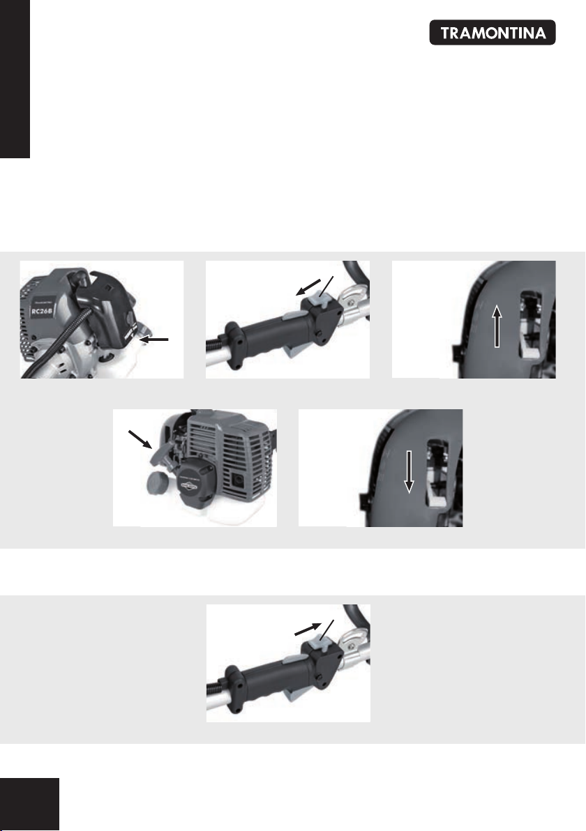
1. Remova a tampa do filtro de ar, [Fig. 30, 31].
2. Remova o filtro, [Fig. 32].
3. Limpe o filtro lavando com água e sabão e deixe-o secar completamente.
4. Mergulhe em uma mistura de 25:1 de combustível de dois tempos e esprema o excesso.
5. Montar em ordem inversa.
Tabela de manutenções
Item Manutenção Antes de
cada uso
Intervalos
50 h
Parafusos e Porcas Inspeção/Aperto X
Mangueiras de Combustível Inspeção X
Filtro de Combustível Inspeção/Troca X
Filtro de Ar Limpeza/Troca X
Vela de Ignição Inspeção/Limpeza/Ajuste/Troca X
Silencioso Limpeza X
Silenciador Inspeção/Limpeza X
Caixa de Transmissão Lubrificação X
Conjunto de Corte Inspeção/Troca X
NORMAS BÁSICAS DE SEGURANÇA
•Em qualquer manutenção, limpeza, transporte, armazenagem e regulagem da roçadeira, desligue-a
aguardando a parada do conjunto de corte.
•Não permita que pessoas inexperientes usem a roçadeira sem antes ler o manual de instruções.
•Ligue o equipamento somente quando as mãos e os pés estiverem afastados do sistema de corte.
•Evite ambientes perigosos. Não utilize a roçadeira em lugares úmidos ou molhados.
•Nunca abasteça de combustível com o motor em funcionamento.
•Desligue o motor e deixe-o esfriar pelo menos 2 minutos antes de retirar o tampão do tanque de combustível.
•A gasolina e seus vapores são extremamente inflamáveis e explosivos. O fogo ou uma explosão poderá
provocar graves queimaduras ou morte.
•Dê a partida e faça funcionar o motor em áreas externas. Não acione nem faça funcionar o motor em áreas
fechadas, mesmo que as janelas ou as portas estejam abertas. Os motores liberam monóxido de carbono, um
gás tóxico, inodoro e incolor. Respirar monóxido de carbono poderá provocar náuseas, desmaios ou morte.
•Não utilize a roçadeira na chuva. Utilize sempre durante o dia ou com boa iluminação.
•Mantenha crianças ou animais à distância da roçadeira quando ele estiver em operação. Todas as
pessoas, especialmente crianças devem encontrar-se à uma distância segura da área de trabalho. Não
permita que crianças usem a roçadeira.
Português

•Não force a roçadeira. O equipamento fará o trabalho da melhor maneira possível e com segurança se for
utilizado nas condições designadas.
•Quando não utilizada, a roçadeira deve permanecer fora do alcance das crianças.
•Não seja autoconfiante - Mantenha os pés no solo para manter o equilíbrio.
•Vista-se de maneira adequada - Não use roupas soltas ou joias, pois podem se enganchar nas partes
móveis do equipamento.
•Utilize óculos de segurança, proteção para os ouvidos, luvas e calçados fechados.
•Utilize o equipamento corretamente - Não utilize a roçadeira para nenhum outro trabalho a não ser ao
que lhe foi designado.
TERMOS DE GARANTIA
A TRAMONTINA MULTI S.A. oferece garantia a este produto por ela comercializado contra qualquer
defeito de fabricação pelo período total de 6 (seis) meses, sendo 3 (três) meses de garantia contratual
e 90 (noventa) dias de garantia legal, conforme estabelece o artigo 26 do Código de Defesa do
Consumidor.
O prazo de contagem da garantia inicia-se com a emissão da Nota Fiscal de venda do equipamento,
que deverá ser anexada ao presente termo, sendo que a garantia será válida somente mediante
apresentação da nota fiscal de compra.
O comprador será responsável pelas despesas de embalagem e transporte até o Serviço Autorizado
Tramontina mais próximo.
O comprador é responsável pelas revisões, manutenções e limpezas periódicas necessárias ao
equipamento, bem como pela observação a todos os cuidados dispostos no manual de uso.
São situações não cobertas pela garantia:
- Danos causados pela não observância das orientações contidas neste manual;
- Peças danificadas pelo: desgaste natural, acidentes, uso e manutenção incorreta do aparelho ou
imperícia do operador;
- Avarias decorrentes do uso de óleos lubrificantes e/ou combustíveis inadequados (fora da especificação
técnica);
- Avarias decorrentes da ausência de óleo, óleo insuficiente, óleo em excesso ou diferente do
recomendado;
- Revisões provocadas por problemas de combustível e óleos inadequados (limpeza interna);
- Quando o equipamento apresentar sinais de violação, utilização de peças não originais ou ter sido
consertado por pessoas não autorizadas pela TRAMONTINA.
NOTA
TODAS AS PEÇAS COMPROVADAMENTE COM DEFEITO DE FABRICAÇÃO SERÃO SUBSTITUÍDAS SEM CUSTO,
NÃO HAVENDO A TROCA DO EQUIPAMENTO.
11
Português
Bahia.....................(71) 3215 8266 Porto Alegre........(51) 2101 5000
Belém....................(91) 3211 7700 Recife..................(81) 3454 8800
Belo Horizonte.......(31) 3223 4026 Rio de Janeiro.....(21) 2224 5004
Curitiba.................(41) 2111 9110 São Paulo............(11) 4197 1266
Goiânia.................(62) 3272 2100
Escritórios de Vendas
Imagens meramente ilustrativas
MODELO MOTOR GARANTIA LEGAL +
GARANTIA CONTRATUAL
TEMPO TOTAL DE GARANTIA
A CONTAR DA DATA DA COMPRA
RC26B 26 cc 3 meses + 90 dias 6 meses

12
English
COMBUSTION BRUSHCUTTER
01
02
03
09
07
08
05
04
06
13
10
11
12
14
15
16 17
LEARN ABOUT THIS PRODUCT:
Main Parts and Controls:
01 - Engine
02 - Air Filter
03 - Fuel Pump Primer
04 - Harness Hook
05 - Handle
06 - Accelerator
07 - Ignition Switch
08 - Throttle Lock
09 - Throttle Release
10 - Shaft Split Connection
11 - Debris Guard
12 - Spool
13 - Shoulder Harness
14 - Fuel Tank
15 - Starter Cord
16 - Choke
17 - Spark Plug
18 - Upper Axle
19 - Lower Axle 19
18

English
13
TECHNICAL FEATURES
MEANING OF SYMBOLS
Equipment
Manufacturer
Briggs & Stratton
Engine type
Air-cooled - 2 strokes
Cubic capacity
26 cc
Maximum engine power
1.0 hp
Cylinders
1
Maximum engine speed
7800 rpm
Ignition
Electronic
Fuel
Mixture of gasoline with 4% of 2 strokes oil (25:1)
Fuel tank capacity
400 ml
Dry weight
6 kg

QUICK USE GUIDE
• Before using the brushcutter, carefully read the user’s and maintenance manual.
• Use good quality gasoline mixed with 4% (25:1) 2-stroke oil, and after using, do not leave gasoline in the
fuel tank.
• Before beginning to trim, check the location where the brushcutter will be used and remove any unusual
objects, such as wires, stones, branches, etc.
• Do not use the brushcutter in the rain or under wet conditions.
• Check and clean the air filter before each use.
• Now that you are the owner of a Tramontina brushcutter, you will receive FREE TECHNICAL SUPPORT from
our network of authorized Tramontina service centers.
ASSEMBLY
Always disconnect spark plug H.T. lead before any work.
Spool fitting
1. Replace blade protector, [Fig. 01].
2. Align hole in flange and housing, [Fig. 02].
3. Insert Allen Key (supplied) into hole in flange and housing.
4. Grip the cast head and rotate anti-clockwise to remove.
5. Refitting is in reverse order.
Fitting line
1. Cut a length of line to 45 cm, bend it in half (equal ends). Use only 3 mm diameter nylon line, [Fig. 03, Pag. 04].
2. Push the bent end of the line under the lug of the trimmer head, [Fig. 04, Pag. 04].
3. Push one end of the line into the hole on the same side of the head as the line end. Pull the line through the
hole until loops or slack between the hole and centre lug is removed, [Fig. 05, Pag. 05].
4. Repeat step 3 for opposite side, [Fig. 06, Pag. 05].
5. Refer to image for correct complete assembly of the nylon line into the head, [Fig. 07, Pag. 05].
Removing line
1. To remove used line, bend new line as in, [Fig. 03, Pag. 04], slide new line under used line through slot in cast head,
[Fig. 08, Pag. 04].
2. Holding both ends of the new line together, pull the old line out of the cast head, [Fig. 09, Pag. 04].
3. Repeat process for the other side, [Fig. 10, Pag. 04].
Caution
•Always trim with the correct length of nylon line 45 cm.
•Always ensure that all components are firmly fastened before starting any operation.
•Unequal lengths will cause vibration and damage to unit.
!
14
English
Fig. 01
Blade
Line cutting
blade
Fig. 02
Housing
Spool
hole
Allen
key

15
English
•Excessive trimmer line length will damage guard and clutch.
•Replace line when 5 cm from trimmer head body.
Axle assembly
1. Slacken the star grip screw (1) on the split shaft connection, [Fig. 11, Pag. 06].
2. Then press lever on the shaft split connection (2) and carefully slide the lower haft (4) into the shaft split
connection (3), [Fig. 12, Pag. 06].
NOTE: When doing so, take care to ensure that the drive shafts on the insides of the tubes slide into each
other, (turn spoll gently if required).
3. Ensure that the lever on the shaft split connection locks into the corresponding hole (5), [Fig. 13, Pag. 06].
4. Then re tighten the star grip screw (1), [Fig. 14, Pag. 06].
5. To dismantle, proceed in reverse order.
Handle assembly
1. Remove the wing nut, washer and fastening screw from the handle. Push the handle onto the shaft, [Fig. 15, Pag.
06].
2. Replace fastening screw and tighten with the wing nut, [Fig. 16, Pag. 06].
NOTE: Not too loose or too tight.
Guard assembly
1. Slacken the fastening screw on the guard with the help of the Allen key provided and then remove, [Fig. 17, Pag.
07].
2. Then clip the guard to the lower bent shaft, [Fig. 18, Pag. 07].
3. Screw the guard hood tightly in position with the fastening screw, [Fig. 19, Pag. 07].
Belt assembly
1. The strap is intended to help you work safely and ergonomically with the petrol grass trimmer.
2. Hook the belt into the fastening (1) eyelet, [Fig. 20, Pag. 07].
3. Slip the strap over the shoulder.
4. Set the length of the shoulder strap in such a way that the trimmer head runs parallel to the ground. In order to
establish the optimum length of the strap, you should then make a few swinging movements without starting the
engine, [Fig. 21, Pag. 07].
OPERATION
Fueling
Use good quality gasoline mixed with 4% (25:1) 2-stroke oil in the fuel tank.
Gasoline is highly flammable and can cause serious injury if it is inhaled or comes into contact with the body.
Always use extreme caution when handling fuel. Use adequate ventilation when handling fuel in an enclosed
place.
Never fill up the brushcutter while the engine is running.
When adding fuel, open the fuel tank slowly to allow the release of any excess pressure.
After filling the fuel tank, carefully tighten the fuel tank cover.
Keep the brushcutter at least 10 feet away from the fueling area before turning on the engine.
Immediately wash off with soap and water any fuel that gets on your skin or clothing.
Check that there is no fuel leakage after fueling.
Starting the brushcutter
1. Set the machine down on a hard, level surface.
2. Press the fuel pump primer 10 times, this is found under the air filter housing, [Fig. 22, Pag. 08].

16
!
!
3. Turn the ignition switch (1) to the “ON” position, [Fig. 23, Pag. 08].
4. Set the choke lever to the ‘UP’ position, [Fig. 24, Pag. 08].
5. Pull out the starter cord until you feel it start to resist. Then tug sharply on the starter cord 2 or 3 times or
untill the engine trys to start, [Fig. 25, Pag. 08].
6. Set the choke lever to the ‘DOWN’ position, [Fig. 26, Pag. 08].
7. Pull the starter cord firmly until the engine starts, [Fig. 25, Pag. 08].
8. If the engine does not start, repeat the steps above.
Note: Once the engine has started, always move the choke lever to the “DOWN” position.
To shut off the equipment
1. Turn the ignition switch (1) to the STOP position, [Fig. 27, Pag. 08].
USAGE INFORMATION
Safe use of the equipment
Check the device before each use. Check for any fuel leaks and be sure that all nuts and bolts are correctly in
place and tightened.
Replace all parts that are cracked, torn or damaged before using equipment.
Keep all persons away when adjusting the carburetor.
Fuel is very flammable and can explode. Be careful when handling fuel or filling fuel tank.
Cutting
Before beginning to cut, inspect the area where the brushcutter will be used and remove all hazardous objects,
such as wire, stones, branches, etc.
Place the shoulder harness over your left shoulder, tie around your waist and adjust it so that the clasp sits a
little below the belt-line, [Fig. 28, Pag. 09].
To cut, turn the engine to the highest speed and move the device from right to left. When done with an area,
decrease the engine speed, return to your original position and, before entering the next area of cutting, turn the
engine up again to the highest speed, [Fig. 29, Pag. 09].
Instructions for waste disposal
Improper disposal of oil, gasoline and toxic parts endangers the environment. Such items should be stored in
proper containers and dropped off at authorized collection centers. Recyclable waste items should be recycled.
MAINTENANCE
Always turn off the engine and disconnect the spark plug wire whenever performing any
maintenance.
Maintenance of the air filter
Dirty air filters reduce the engine output by supply too little air to the carburettor.
Regular checks are therefore essential. The air filter should be checked monthly and cleaned if necessary. If the
air contains a lot of dust, the air filter should be checked more frequently.
1. Remove the air filter cover, [Fig. 30 and 31, Pag. 10].
2. Remove the filter element, [Fig. 32, Pag. 10].
English

English
17
3. Clean the filter element by washing in soapy water and allowing it to dry completely.
4. Soak in a mixture of 25:1, 2 stroke fuel and squeeze off excess.
5. Assemble in reverse order.
Maintenance table
Iten Maintenance Before
each use
Frequency
50 h
Screws, Nuts and Bolts Inspect/Tighten X
Fuel Hoses Inspect X
Fuel Filter Inspect/Replace X
Air Filter Clean/Replace X
Spark Plug Inspect/Clean/Check-Adjust/Replace X
Muffler Clean X
Cooling System Inspect/Clean X
Gearbox Lubricate X
Cutting Parts Inspect/Replace X
BASIC SAFETY RULES
•Always shut off the brushcutter and wait for the cutting mechanism to fully stop before doing any
maintenance, cleaning, transporting, storing or adjusting of the device.
•Do not allow anyone unfamiliar with the brushcutter to use it without first reading the instruction manual.
•Keep hands and feet away from the cutting mechanism when turning on device.
•Avoid unsafe conditions. Do not use the brushcutter under humid or wet conditions.
•Never fill with fuel while the engine is running.
•Shut off the engine and let it cool down for at least 2 minutes before opening the fuel tank.
•Gasoline and gasoline fumes are extremely inflammable and explosive. Fire or an explosion can cause
serious burns and even death.
•Only use the device outdoors. Do not use or turn on the device in enclosed areas, even if windows and
doors are left open. Engines release carbon monoxide, a scentless and colorless gas. Inhaling carbon
monoxide can cause nausea, fainting and even death.
•Do not use the brushcutter in the rain. Always use it during daylight or with good lighting conditions.
•Keep children and animals away from the brushcutter when it is in operation. Everyone, especially children,
should keep a safe distance from the work area. Do not allow children to use the brushcutter.
•Do not force the brushcutter. The equipment will work best and in the safest manner if it is used as
intended.
•Keep the brushcutter out of the reach of children when not in use.
•Do not take risks; keep both feet firmly on the ground to maintain your balance.
•Wear suitable clothing. Do not wear loose clothing or jewelry as they can get caught in the machine’s
moving parts.
•Use safety glasses, ear protectors, gloves and closed-toe shoes.
•Use the brushcutter properly. Do not use it for any purpose other than for what it was intended.

WARRANTY TERMS
TRAMONTINA MULTI S.A. guarantees this product against any manufacturing defect for a period of 6
(six) months, of which 3 (three) months are contractual warranty and 90 (ninety) days are legal warranty,
according to article 26 of the Consumer Protection Code.
The period of this warranty dates from the date of emission of the equipment sales receipt, which should be
attached to this agreement, with the warranty only being valid on presentation of the sales receipt.
The purchaser is responsible for shipping and packaging costs to the nearest Tramontina Authorised Service
provider.
The purchaser is responsible for the equipment’s necessary periodical inspection, maintenance and cleaning, and
also for observing all the care requirements in the user’s manual.
The following are not covered by warranty:
- Damage caused by not following the guidance in this manual;
- Parts damaged by natural wear, accident, incorrect use and maintenance of the equipment or operator misuse;
- Damage resulting from inappropriate use of lubricants or fuel (beyond technical specifications);
- Damage resulting from lack of oil, insufficient oil, excess oil or different from that recommended;
Revision caused by inappropriate fuel and oil problems (internal cleaning);
Necessary periodical cleaning, maintenance and inspection of the equipment;
Equipment displaying signs of tampering, use of non-original parts, or repair by people not authorised by
TRAMONTINA.
NOTE
ALL PARTS PROVEN TO HAVE MANUFACTURING DEFECTS WILL BE REPLACED FREE OF CHARGE.
THE EQUIPMENT WILL NOT BE EXCHANGED.
18
English
MODEL ENGINE
CONTRACTUAL
WARRANTY + LEGAL
WARRANTY
TOTAL WARRANTY PERIOD FROM
PURCHASE DATE
RC26B 26 cc 3 months + 90 days 6 months
Pictures merely illustrative

19
Español
DESBROZADORA A COMBUSTIÓN
01
02
03
09
07
08
05
04
06
13
10
11
12
14
15
16 17
19
18
CONOZCA EL PRODUCTO
Partes Principales:
01 - Motor
02 - Filtro de Aire
03 - Cebador de Combustible “Primer”
04 - Gancho del Cinturón
05 - Manubrio
06 - Acelerador
07 - Interruptor de Encendido
08 - Bloqueo del Acelerador
09 - Liberador del Acelerador
10 - Conexión de División de Ejes
11 - Protector
12 - Carretel de Hilo de Nylon
13 - Cinturón de Soporte
14 - Tanque de Combustble
15 - Cordón de Accionamiento del Motor
16 - Regulador
17 - Bujía
18 - Eje Superior
19 - Eje Inferior

Español
20
Equipo
Fabricante
Briggs & Stratton
Tipo de motor
2 tiempos, enfriado a aire
Cilindradas
26 cc
Potencia
1,0 hp
Cilindros
1
Velocidad máx. del motor
7800 rpm
Sistema de ignición
Electrónico sin platinado
Combustible
Mezcla de gasolina com 4% de aceite 2 tiempos (25:1)
Volumen del tanque de combustible
400 ml
Peso (en seco)
6 kg
CARACTERÍSTICAS TÉCNICAS
SÍMBOLOS
Other manuals for RC26B
1
Table of contents
Languages:
Other Tramontina Brush Cutter manuals