LawnMaster BC451 Installation manual

LMCG260EH
SAFETY AND OPERATING MANUAL
PLEASE READ THIS MANUAL CAREFULLY BEFORE OPERATING THE UNIT
45CC
BRUSH CUTTER
PROUDLY
NZ OWNED
A STEELFORT PRODUCT
BC451

2A STEELFORT PRODUCT
OPERATOR SAFETY 3
GETTING STARTED 5
Assembly
FEATURES & TECHNICAL DATA 9
OPERATION 10
Fuel & Oil Mixture
Rules for Operation
Preparing for Operation
STARTING THE BRUSH CUTTER 11
Starting the Engine
Fitting the Belt
Cutting with the Brush Cutter
Extending the Cutting Line
Stopping the Engine
MAINTENANCE & STORAGE 14
Maintenance Schedule
Air Filter
Spark Plug
Cleaning
Angle Transmission
Storage
TROUBLESHOOTING 18
WARRANTY 19
TABLE OF CONTENTS

3
A STEELFORT PRODUCT
Thank you for purchasing our LawnMaster BC451
Brushcutter , the information contained within this
manual will help you to have many years of safe
and trouble free use of this Lawnmaster product.
OPERATOR SAFETY
SAFETY RULES
This manual contains important safety information
and instructions to operate the LawnMaster Brush
Cutter.
PLEASE READ THIS MANUAL CAREFULLY BEFORE
USING THE UNIT.
Failure to adhere to the safety instructions could
result in property damage and/or serious personal
injury.
This manual should be considered a permanent part
of the brush cutter and should remain with the unit at
all times. All information in this publication is based
on the latest product information available at the
time of printing.
Product Information and specications can be
altered and/or improved without notice.
Content from this publication may not be reproduced
without written consent.
DANGER
Indicates a hazardous situation which, if not strictly
complied with, will result in substantial property
damage and or serious injury.
WARNING
Indicates a hazardous situation which, if not strictly
complied with, may result in property damage
CAUTION
Indicates a hazardous situation which, if not strictly
complied with, could result in property damage or
personal injury.
The warnings and precautions discussed in this
manual does not cover all possible conditions and or
scenarios that may occur.
It must be understood by the operator that common
sense and caution must be taken into consideration
when operating this product, as these are factors
which cannot be built into this manual.
DANGER
TOXIC FUMES
• The exhaust of the engine contains carbon
monoxide, an odorless, colorless poison gas.
Using the engine in conned/indoor spaces can
be extremely dangerous and life threatening.
FIRE
• When operating the unit, the engine may create
sparks that could trigger res.
• When operating around dry vegetation such as
agricultural crops, forest, bush, grass, or other
similar environments please be careful.
• This engine may not be equipped with a spark
arresting muer. In some countries and
regions, a spark arrester is required by law.
Please contact your local council and or re
agency for laws and regulations relating to re
prevention requirements.
• Petrol is highly ammable and explosive. A re
and or explosion from petrol can cause severe
burns or result in serious personal injury includ-
ing death.
• Keep ammable items away while handling
petrol. Fill fuel tank outdoors and in a well
ventilated area with the engine stopped.
• Always wipe spilled fuel and wait until the fuel
has dried before starting the engine.
• DO NOT operate the engine with known leaks
in the fuel system. Use proper fuel storage and
handling procedures.
• Empty the fuel tank before storing or
transporting the brush cutter.
• Keep re extinguisher handy at all times.
HOT SURFACE
• Running the brush cutter will produce heat and
severe burns may occur upon contact. DO NOT
touch the engine while under operation or just
after stopping the unit.
• Avoid contact with hot exhaust gases and or
hot surfaces.
• Maintain at least 1m of clearance on all sides to
ensure adequate cooling. Combustible material
can catch re upon contact. Maintain at least
3m of clearance from combustible materials.
GENERAL WARNINGS
• Before use, check for loose or damaged parts,
signs of oil or fuel leaks, and any other
condition that may impact operation.

4A STEELFORT PRODUCT
• Repair or replace all damaged and or defective
parts immediately.
• Locate all operating controls and safety labels.
• Make sure all the safety instructions are in
correct working condition.
• Keep all safety guards in place and in proper
working order at all times.
• DO NOT allow any material to block the cooling
slots.
• DO NOT allow children or untrained people to
operate the unit.
• Read the instructions carefully. Be familiar
with the controls and the proper use of the
appliance.
• This product has been designed for use in
cutting grass, and it should never be used for
any other purpose.
• Never use while people, especially children, or
pets are nearby.
• The operator or user is responsible for
accidents of hazards occurring to other people
or their property.
• Always store fuel in a properly marked
container that complies with New Zealand
standards.
• Do not mix fuel in an enclosed room or near an
open ame, ensure adequate ventilation.
• Never attempt to make engine adjustments
while the engine is running and strapped to the
operator.
PREPARATION
• Petrol is highly ammable: Store fuel in con-
tainers specically designed for this purpose;
refuel outdoors only and do not smoke while
refueling;add fuel before starting the engine.
Never remove the cap of fuel tank or add petrol
while the engine is running or when the engine
is hot; if petrol is spilled, do not attempt to
start the engine but move the machine away
from the area of spillage and avoid creating
any source of ignition until petrol vapors have
dissipated. Replace all fuel tank and container
caps securely.
• Replace faulty silencer.
• Before using, always visually inspect to see that
the tools are not worn or damaged. Replace
worn or damaged elements and bolts in sets to
preserve balance.
• Never put any items into the ventilation open-
ings. Non-observance may lead to injury, or
damage to the machine.
• It is necessary reduction in power due to use in
higher temperatures, altitudes and humidity as
below conditions.
Max Working Temperature: 40°C
Max Altitude: 1000 m
Max Humidity: 95%
OPERATION
• Do not operate the engine in a conned space
where dangerous carbon monoxide fumes can
collect.
• Keep the machine free of oil, dirt and other
impurities.
• Always place the appliance on even and stable
surfaces.
• Never operate the appliance inside buildings or
in an environment without proper ventilation.
• Do not operate or store the appliance in wet or
humid surroundings.
• Ensure the sound absorber and air lter work
properly.
• Do not touch the exhaust system or other parts
that become hot during operation.
• The engine must not be operated with
excessive rotary speed. The operation of the
engine with excessive rotary speed raises the
risk of injury.
• Regularly check for leakage or traces of
abrasion in the fuel system, such as porous
pipes, loose or missing clamps and damage to
the tank or tank cap.
• Work only in daylight or in good articial light.
• Never pick up or carry a machine while the
engine is running.
• Stop the engine whenever you leave the
machine and before refueling.
• Before checking or adjusting the machine, the
ignition plug and the ignition wire respectively
must be removed to prevent accidental
starting.
• Do not use the machine when the operator is
tired, ill or under the inuence of alcohol or the
drugs.
• Wear safety goggles and ear protection.
• Ensure that you maintain a steady foothold.
• Only use the brush cutter on at surfaces
where you have a rm footing.
• Always wear substantial footwear and long
trousers. Do not operate the equipment when
barefoot or wearing open sandals.
5
A STEELFORT PRODUCT
• Always hold the brush cutter with two hands
• Always use the harness when operating, adjust
the length of the harness to ensure it is suitable
for operation.
• Always use the correct blade and spool
recommended by the manufacturer.
• Always ensure that the ventilation openings are
kept clear of debris.
• Perform inspection before use and after any fall
or other impact to identify signicant defects.
• Rest frequently and change working positions.
Keep balance position during operation, use the
harness.
WARNING
It has been reported that, for some people, the
vibrations produced by the motorized hand tools can
lead to develop a disease called Raynaud’s syndrome
or white nger. Symptoms may include tingling,
numbness and blanching of the ngers, usually
caused by exposure to cold. There is currently no
evidence that a certain type of vibration or exposure
actually contributes to the development of this
assignment. Some measures that can reduce the
effects of vibration, can be taken by the operator:
• Keep your body warm in cold weather. During
use, wear gloves to keep your hands and wrists
warm. It has been reported that cold weather is
one of the main causes of Raynaud’s Syndrome.
• After each period of operation, exercise to
increase circulation.
• Take frequent breaks. Limit the duration of
daily exposure.
• Keep the tool well maintained, all fasteners
tightened and worn parts replaced.
• In case of occurrence of one or more of the
symptoms described above, stop using the tool
and seek medical attention.
•
GETTING STARTED
The brush cutter is a high-speed and fast cutting
power tool. All safety precaution must be
observed to reduce the risk of personal injury. Please
read this manual carefully and become familiar with
the controls before using the unit.
ASSEMBLY
When assembling this machine, please follow the
instructions for assembly printed.
INSTALL THE MAIN BODY
Connect the engine (A) to the tube (B) with four
screws (C).
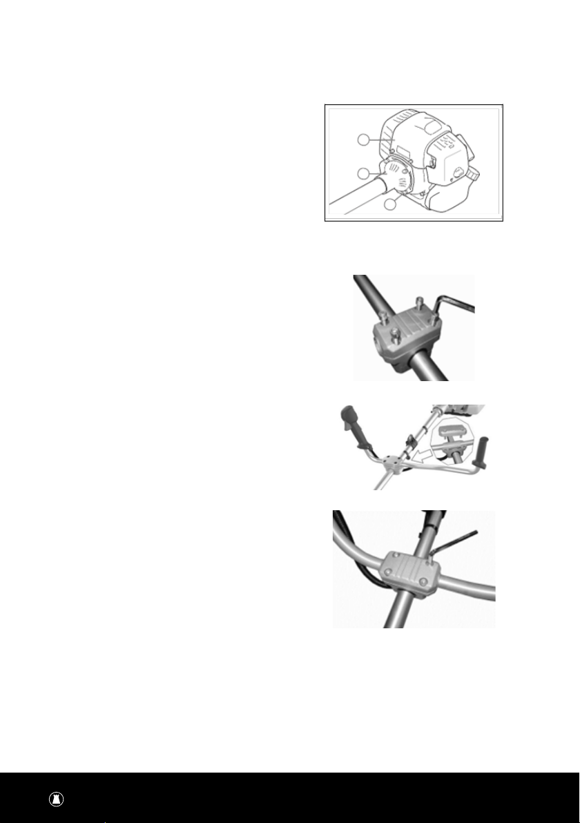
ASSEMBLY OF THE HANDLE
(FIG.1-1,1-2,1-3)
1. Remove the screws inxing device and remove
the upper cover. (Fig.1-1)
2. Place the handle in position and assemble the
upper cover. (Fig.1-2)
3. Assemble and tighten the screw. (Fig.1-3)
FIG.1-1
FIG.1-2
FIG.1-3
6A STEELFORT PRODUCT
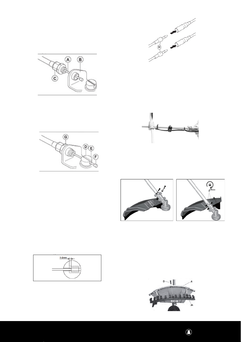
CONNECT THE TROTTLE CABLE AND STOP SWITCH
WIRES
1. Remove the air lter cover
2. Install the throttle cable (A) through the
carburettor bracket (B)
3. Turn the cable adjuster sleeve (C) into the
carburettor bracket fully
4. Put the slot tting (D) on the carburettor. At this
time the recessed hole (E) throttle cable plug
(F) is away from the cable adjuster sleeve (C)
5. Rotate the carburettor throttle cam and move
the throttle cable (A) through the slot in the slot
tting.
6. Make sure the cable lug (F) drops into the
recessed hole.
7. Operate the throttle trigger some times to make
sure that it operates correctly.
8. Adjust the cable adjuster sleeve (C).
9. Make sure the stop on the carburettor throttle
cam touches the throttle stop correctly.
10. Make sure the cable position keeps 1-2 mm
between cable lug (F) and slot tting when the
throttle trigger is fully pushed.
11. When the throttle cable (A) is adjusted correctly,
tighten the lock nut (G).
12. Connect the stop switch wires (H) with the
connectors from the engine.
13. Install the air lter cover.
WARNING
Do not tighten the screws until you have set the
handle in optimal working position. Please always
adjust the handle position with full assembled
accessories. The black cable tie can be used to x
the throttle cable to the metal tube. (Fig.2)
ASSEMBLE THE GUARD
(FIG.3-1, FIG.3-2)
1. Place the guard on the xture. (Fig3-1)
2. Assemble and tighten the screws. (Fig.3-2)
WARNING
When using the cutting line head, the additional
guard, with line cutting knife, must always be tted.
(Fig.3-3,Fig.3-4)
Secure the additional guard (26) using the screw (B).
(Fig.3-3)
FIG.3-1 FIG.3-2
FIG.3-3

7
A STEELFORT PRODUCT
TAKE OFF ADDITONAL GUARD
1. Screw off the screw (B); (Fig. 3-3)
2. Push the clip (C), and pull out the additional
guard. (Fig.3-4)
WARNING
Please check the blade and output shaft after
each adjustment or assembly, it must be correctly
assembled and running smoothly. Wear protective
gloves when handling the guard.
FITTING THE 3T BLADE
(FIG. 4)
Take the outer ange off after release the nut, then
put the blade, outer ange, shield and nut according
to priority as below picture. Note the blade rotation
direction needs be same as below picture. Use
screw driver to hold ange and tighten nut counter-
clockwise, ensure the nut is tightened enough.
RELEASE THE BLADE
(FIG 5)
Use screw driver to hold ange and release nut, the
blade can be took off.
WARNING
Please make sure the cutting head has been
FIG.3-4
assembled correctly before use!
NYLON HEAD
RELEASE THE NUT
(FIG.6)
Line up the two holes of ange and shield, use one
screw driver to hold the ange as below and turn the
socket wrench clockwise, the nut will be released
FIT THE NYLON CUTTING HEAD
(FIG.7)
Remove another shield after release the nut. Still hold
the ange, take the Nylon cutting head on the shaft
and rotate counter-clockwise, the Nylon cutting head
is tted.
RELEASE THE NYLON CUTTING HEAD
(FIG.8)
Remove another shield after release the nut. Still hold
the ange, take the Nylon cutting head on the shaft
and rotate counter-clockwise, the Nylon cutting head
is tted.
FIG.4-1
FIG.5-1 FIG.5-2
FIG.6
FIG.7
FIG.8

8A STEELFORT PRODUCT
REPLACING LINE
1. Unclip the housing from the line trimmer and
remove spool from the spindle.
2. Remove all remaining cutting line from the
spool.
3. Cut 2m of line. Fold in half and attach the mid-
dle of the line into the grove/slot located in the
center of the spool.
4. Wind both sides of the line on to the
spool with tension in the same direction as
shown on the inside of the spool. (See above
right image)
5. Continue to wind the line until you have 150mm
of line left on each end. Note: It is helpful to
clip and fasten the line on opposite ends of the
spool to keep the line from unraveling during
the next step.
6. Put the spool into housing. Unclip the line from
the spool and place line through the open eyelet
on opposite ends of the housing. Ensure the line
has not tangled.
7. Clip the housing back onto the line trimmer

9
A STEELFORT PRODUCT
FEATURES & TECHNICAL DATA
1. Tube
2. Throttle Trigger
3. Engine Switch
4. Throttle Trigger Lockout
5. Suspension Point
6. Cable
7. Muer Cover
8. Cylinder Cover
9. Spark Plug Cover
10. Air Filter Cover
11. Choke Lever
12. Fuel Tank Cap
13. 3T Blade
14. Gearbox
15. Guard Fixture
16. Cutting Attachment Guard
17. Socket Wrench
18. Spanner
19. Allen Keys S5
20. Allen Keys S4
21. Trimmer Head
22. Harness
23. Fuel Mixture Container
24. Line Cutter
25. Additional Guard
Technical Data is subject to change without notice.
MODEL LMBC451
Idle speed (r/min) 2500 +/ - 500
Nylon Head Twin Line Tap & Go Head
Engine Air-Cooling, 2 Stroke
Spark Plug NGK BPMR7A / BOSCH WSR6F
Displacement (cc) 44.8
Maximum Cutting Speed 10000 +/- 500
Maximum Cutting Diameter 430mm
Maximum Output (kw) 1.6
Ignition Electronic
Spool For Grass Trimmer 2.7 Diameter Line x 2m Length
Method of Starting Soft Start Recoil
Fuel Used Gasoline mixed with 2 stroke oil 25:1
Fuel Tank Capacity 920ml
Weight 9kg

10 A STEELFORT PRODUCT
OPERATION
1. FUEL & OIL MIXTURE
Never use oil for 4-cycle engine use or water-cooled
2-cycle engine. It can cause spark plug fouling
exhaust port blocking or piston ring sticking.
Mixed fuels, which have been left unused for a period
of one month or more may clog the carburetor
or result in the engine failing to operate properly. Put
remaining fuel into an airtight container and
keep it in the dark and cool room.
WARNING
The brush cutter is tted with a two-stroke engine;
use fuel mixed with oil only.
DANGER
Fuel is explosive. Turn off and cool the motor down
before lling the tank with fuel. You must observe all
safety instructions relating to handing fuel.
Fuel used for this model is a mixture of unleaded
gasoline and approved engine lubricant. When mixing
petrol with two-cycle engine oil, use only petrol that
DOES NOT contain ETHANOL or METHANOL (types of
alcohols).
Use 91 unleaded petrol to fuel the unit. This will help
avoid possible damage to the engine fuel lines and
other engine parts.
FUEL
The engine uses two-stroke fuel. If you have
emission requirements, the mixture ratio of the fuel
to oil should be 25:1
Be careful, a wrong mixture of the fuel will cause
machine failure.
PETROL
Use 91 and above unleaded fuel.
We recommend unleaded petrol as it leaves fewer
residues inside the motor and on the ignition plug, and
prolongs the life cycle of the exhaust system. Never
use old or dirty petrol or oil/petrol mixtures
STORING FUEL
The tank to store the fuel should be clean, anti-static,
high-temperature-resistant, re prevention and safe.
IMPORTANT
Two-stroke fuel may separate. Shake fuel container
thoroughly before every use. Do not mix more fuel
than you expect to use within a month. Take care of
the emission of exhaust gases. Always shut off en-
gine before fueling. Never add fuel to a machine with
a running or hot engine. Never smoke whilst refueling
and avoid inhaling the petrol fumes. Carefully open
the tank top as pressure could have formed inside.
BEFORE REFUELING
• Shake the fuel mixture container well.
• Make sure the machine is turned off, by turn the
engine switch to the “off” position.
• Check the fuel by a visual check, remove the
fuel cap and review the fuel level.
• Fill unleaded fuel / oil mix from an approved
fuel container into the fuel tank, because of
fuel expands, please ll the tank to the neck of
tank only.
• Turn the fuel cap clockwise to assemble it in
position.
DRAINING FUEL
• Hold a collection container beneath the fuel
drain bolt.
• Unscrew the fuel cap and remove it.
• Allow the fuel to run out completely
• Screw the fuel cap on rmly by hand.
FUEL MIXTURE CONTAINER
• Place the fuel mixture container on even and
steady surface.
• First ll the gasoline to the scale marked gas
“500”.
• Then ll the 2-stroke engine oil until the scale
marked oil “25:1”.
• Shake the container gently, and then ll into the
fuel tank.
Oil - 1 Part
Gasoline - 25 Part
Emissions
Petrol 2-Stroke Oil
1 Litre 40 ml
2 Litre 80 ml
5 Litre 200 ml

11
A STEELFORT PRODUCT
2. RULES FOR SAFE OPERATION
WARNING
Read the “Rules for Safe Operation “with care and
follow the instructions in the manual to operate the
unit safely.
Read and be thorough with the basic controls and
functions of the unit. It is important that you know
how to stop and to shut off the engine, and to unhook
a harnessed unit quickly.
Do not allow anyone without proper instruction or
training to operate the unit. All operators of the unit
should wear appropriate foot, leg, eye, face and
hearing protection. Do not rely on the debris shield on
the unit to protect your eyes from thrown objects.
Keep the area clear of bystanders, children and pets.
Never allow children to operate or play with the unit.
Do not allow anyone to enter the operating DANGER
ZONE with you. The danger zone is an area 15 meters
in radius (about 16 paces) or 50 feet.
Insist that persons in the RISK ZONE beyond the
danger zone wear eye protection from thrown
objects. If the unit must be used where there are
unprotected people, operate at a low throttle speed
to reduce the risk of thrown objects.
Move the stop switch to “stop” position when the
engine idles, insure it reliable before cutting. Only
may continue to operate the unit when stop switch is
in good condition.
Routines for checking that the cutting attachment
stops turning when the engine idles.
WARNING
In addition to head, eye, face and ear protection,
please wear appropriate footwear to protect your
feet and to improve footing on slippery surfaces.
Do not wear open-toed footwear, or go bare foot or
barefeet.
3. PREPARING FOR OPERATION
IMPORTANT
Failure to follow proper fuel mix instructions may
cause damage to the engine.
When preparing fuel mixture, mix only the amount
needed for the job you intend to do. Do not use fuel
that has been stored longer than two months. Fuel
mixture stored longer than this will cause hard start-
ing and poor performance. If fuel mix has been stored
longer than this time, it should be removed and lled
with a fresh mixture.
WARNING
• Never ll the fuel tank to the brim. (Under 3/4
of the tank)
• Never add fuel to the tank in a closed non-ven-
tilated area.
• Do not add fuel to this unit close to an open re
or sparks.
• Be sure to wipe spilled fuel before attempting
to start the engine
• Do not attempt to refuel a hot engine.
CHECK POINTS BEFORE OPERATION
• Check for loose bolts, nuts and ttings.
• Check the air lter for dirt. Clean before
operation.
• Check to be sure that protector is securely in
place.
• Check that fuel isnt leaking.
STARTING THE BRUSH CUTTER
STARTING THE ENGINE
WARNING
The cutting attachment may start to move when the
engine is started. Make sure the attachment can not
come into contact with any object.
Make sure that no unauthorised persons are in the
working area, otherwise there is a risk of serious
personal injury.

12 A STEELFORT PRODUCT
1. Press the fuel pump several times until it lls
with fuel. (Fig.12)
2. Turn the engine switch to the ”I “position.
(Fig.13) Press the throttle trigger, throttle
trigger lockout and lock pin together to lock the
trigger .
WARNING
the switch is auto-returned switch, it would always
stays in “I” position, press it to “O” manually if needed.
3. In Res.13, Press the trigger lock to activate the
trigger, then press the trigger lock pin together
to make the trigger half open. This is for easier
starting.
4. Move the choke lever to position. (Fig.14)
5. Close the choke: Start Position
WARNING
Ensure the cutting attachment stops when the engine
is idling. Note that initial engine startup may require
multiple attempts for the fuel to reach the motor.
6. Turn the choke lever to the run position. (Fig.16)
7. Pull the starter quickly until the engine starts.
8. Press the trigger (in Res.13) to release the
trigger lock pin.
9. After starting, let the engine run for 2 to 3
minutes before subjecting it to any load.
HOT START
When the machine is hot, keep the choke level in
“Start position”, the user can start the machine by
repeating steps of 1,2,6,7.
WARNING
Under the following conditions the machine MUST be
stopped.
• When the motor rotary speed changes
• When sparks occur
• When blades are damaged
• In case of misre
• In case of high vibration
• When ames or smoke appear
• In rain or stormy weather
Check the cutting attachment always stops when the
engine is idling.
FITTING THE FULL VEST HARNESS
(FIG.17)
FIG.12
FIG.13
FIG.14
FIG.15
FIG.16

13
A STEELFORT PRODUCT
Fit the harness well. Stretch the harness as below pic,
and then t on shoulder.
The design and type of carry strap may vary.
1. Place the full vest harness over your shoulders
and clip in the middle.
2. Adjust to suit as so the harness is comfortable
to wear.
3. Clip the BC451 on to the harness
4. Adjust the full vest harness if required to
balance the BC451 on the harness.
WARNING
This carry strap has a safety device allowing you to
immediately disconnect the strap from the machine
in an emergency. To do so, pull forcefully on the red
pull tab (3) on the strap. This disconnects the strap
from the holding xture immediately. NOTE: Never
start the motor with the carry strap attached to the
machine!
CUTTING WITH THE BRUSH CUTTER
Avoid operating the cutting tool at a speed just above
clutch engagement to prevent premature clutch
wear. Additionally, it is not recommended to continu-
ously run the engine at maximum speed after cutting,
as this can shorten the engine’s lifespan.
WARNING
In an emergency, stop the engine by moving the
engine switch to the stop position.
After the cutting attachment hits stone or debris,
stop the engine and inspect for any damage or loose
attachment. If the cutting attachment retains wet
grass or branches, stop the engine and remove them.
CUTTING ATTACHMENTS
Only use orginal cutting devices from the
manufacturer
WARNING
The user assumes responsibility for any damages
resulting from the selection, application, and usage
of the accessory. When unsure or lacking knowledge
about specic accessories, it is advised to contact
your LawnMaster Sercie Dealer.
KICKBACK
Kickback occurs when a rotating blade is pinched or
snagged, causing the power tool to forcefully move
in the opposite direction of the blade’s rotation at the
binding point. The blade can jump towards or away
from the operator, depending on its movement during
pinching.
Kickback is the result of power tool misuse and/or
incorrect operating procedures or conditions and
can be avoided by taking proper precautions as given
below.
• Maintain a rm grip on the tool and position
your body and arm to allow you to resist kick
back forces.
• Never place your hand near the rotating acces-
sory. Accessory may kick back over your hand.
• Exercise caution when working near corners,
sharp edges, or during bouncing to prevent
snagging the accessory. Snagging can lead to
loss of control or kickback.
EXTENDING THE CUTTING LINE
FIG.17.1
FIG.18
FIG.19

14 A STEELFORT PRODUCT
WARNING
Avoid metal wire or wire encased in plastic in the
cutting head to prevent injuries. To extend the line,
run the motor at full speed and tap the cutting head
on the ground. This will automatically lengthen the
line, with the cord cutter trimming it to the proper
length (Fig. 20).
FIG.20
MAINTENANCE & STORAGE
It is the operator’s responsibility to complete all scheduled maintenance and or servicing in a timely manner.
Always correct any issues before operating the brush cutter. Follow all inspection and
maintenance recommendations that are listed in the manual.
WARNING
Improper maintenance and or failure to correct problems prior to operating the unit may cause the unit to
malfunction and result in property damage and or serious personal injury. Improper maintenance and servicing
may void warranty.
During maintenance operations:
• Remove the spark plug cap.
• Wait until the engine is suciently cold.
• Never dispose of oils, fuel or other polluting materials in unauthorized places.
Before performing any maintenance or cleaning work, always turn off the engine.
1. Do not spray the unit with water. Ingress of water may damage the engine and electrical connection.
2. Clean the unit with a cloth, hand brush, etc.
MAINTENANCE SCHEDULE
STOPPING THE ENGINE
1. Release the throttle trigger and let it run idling
for a few minutes.
2. Switch off the engine by moving the engine
switch to the stop position.
Ensure the cutting attachment has completely
stopped turning before setting down the unit to
prevent potential accidents.
MAINTENANCE DAILY
MAINTENANCE
WEEKLY
MAINTENANCE
MONTHLY
MAINTENANCE
Clean the outside of the machine.
Make sure the throttle trigger lock and
the throttle function correctly from a
safety point of view.
Check that the engine switch works
correctly.

15
A STEELFORT PRODUCT
MAINTENANCE DAILY
MAINTENANCE
WEEKLY
MAINTENANCE
MONTHLY
MAINTENANCE
Clean the outside of the machine.
Make sure the throttle trigger lock and
the throttle function correctly from a
safety point of view.
Check that the engine switch works
correctly.
MAINTENANCE DAILY
MAINTENANCE
WEEKLY
MAINTENANCE
MONTHLY
MAINTENANCE
Check that the blades do not move when
the engine is idling or when the choke is
in the start throttle position.
Check that the blades are undamaged
and show no signs of cracking or other
damage. Replace the blades if necessary.
Check that the blade guard is not
damaged or distorted. Replace the blade
guard if it is bent or damaged.
Clean the air lter. Replace if necessary.
Check that nuts and screws are tight.
Check that there are no fuel leaks from
the engine, tank or fuel lines.
Check the starter and starter cord.
Clean the outside of the spark plug.
Remove it and check the electrode gap.
Adjust the gap to 0.6-0.7 mm or replace
the spark plug. Check that the spark plug
is tted with a spark plug cap.
Clean the machine’s cooling system.
Clean the outside of the carburetor and
the space around it.
Check the ange, cap and nut are assem-
bled correctly and tightened
Clean the fuel tank.
Check all cables and connections.
Check the clutch, clutch springs and
the clutch drum for wear. Replace if
necessary by an authorised LawnMaster
Service Agent.
Replace the spark plug. Check that the
spark plug is tted with a spark plug cap.
To reduce the re hazard, clean dirt,
leaves and surplus lubricant, etc from the
muer and engine.

16 A STEELFORT PRODUCT
MAINTENANCE
Should be carried out at REGULAR
INTERVALS in each of the indicated
months or after a certain number of
hours of operation (whichever comes
rst). (1)
BEFORE USE
EVERY TIME
MONTHLY OR
AFTER 25
HOURS
EVERY THREE
MONTHS OR
AFTER 50
HOURS
EVERY SIX
MONTHS OR
AFTER 100
HOURS
Air Filter Clean
Fuel Tank & Filter Clean
(1)
(2)
Fuel Feed Line Check (replace
if necessary)
Every three years
(2)
(1) If operated in dusty areas carry out maintenance more frequently.
(2) A specialist technician should carry out this maintenance if the owner does not have the appropriate tools or
mechanical knowledge.
AIR FILTER
(FIG.21)
WARNING
Cleaning the air lter is essential to guarantee the
eciency and duration of the machine. Do not work
with a damaged lter or without a lter, as this could
permanently damage the engine.
Clean the lter as follows:
• Loosen the knob (3), remove the cover (1) and
the lter element (2).
• Wash the lter element (2) with soap water. Do
not use petrol or other solvents.
• Leave the lter to dry in the open air.
• Fit the lter element (2) and the cover (1) back
on, tightening the knob (3) again.
•
WARNING
The use of petrol or combustible solvents for
cleaning can cause re or explosion. Therefore only
use soap water or non-combustible solvent. Never
operate the machine without the air lter.
SPARK PLUG
RECOMMENDED SPARK PLUG: NGK BPMR7A / BOSCH
WSR6F To ensure proper engine operation, the spark
plug must be properly gapped and free of deposits.
1. Remove the spark plug cap.
2. Clean any dirt around the spark plug base.
3. Use the socket spanner which provided to
remove the spark plug.
4. Visually inspect the spark plug. Remove carbon
deposits using a wire brush.
5. Check for discoloration on the top of the spark
plug. The standard color should be a tan color.
6. The acceptable spark plug gap should be
between 0.6 - 0.7mm.
FIG.21

17
A STEELFORT PRODUCT
7. Install /reinstall the spark plug carefully by
hand.
8. Once the spark plug has been seated, tighten it
with a socket spanner.
9. Reinstall the spark plug cap on top of the spark
plug
FIG.22
CLEANING
1. To keep your machine clean, use a damp cloth
with mild detergent for the exterior—avoid
water to prevent internal damage.
2. Some maintenance products and solvents may
damage the plastic parts, these include prod-
ucts containing benzene. Trichloroethylene,
chloride and ammonia.
3. Keep ventilation inlets/outlets clear. Use a
soft brush and compressed air for internal
cleanliness.
4. Wear eye protection when carrying out clean-
ing.
ANGLE TRANSMISSON
(FIG.22)
Lubricate with lithium-based grease.
Remove the screw (1) and put in the grease, turning
the shaft manually until grease emerges, then
replace the screw (1).
STORAGE
At the end of each working session, carefully clean
the machine of dust and debris, and make sure
that there are no damaged parts, replacing any faulty
parts. The machine must be stored in a dry
place away from the elements and with the cover
correctly tted.
• Keep all nuts and screws tight to be sure the
equipment is in safe working condition.
• Never store the equipment with petrol in the
tank inside a building where fumes can reach
an open ame or spark.
• Allow the engine to cool before storing in any
enclosure.
• To reduce the re hazard, keep the engine,
silencer and petrol storage area free of vegeta-
tive material and excessive grease.
• Replace worn or damaged parts for safety.
• If the fuel tank has to be drained, this should be
done outdoors.
• Always clean and maintenance before storage.
• Never disassembly the guards for cutting
attachments.
• Always store the metal blade in cool and dry
place, never use rusted blade. It may cause
serous injure during working.
Transporting the machine in a car, please empty the
fuel tank completely rst to avoid the leakage.
Store the machine, operating instructions and where
necessary the accessories in the original packaging
.In this way you will always have all the information
and parts ready to hand.
Pack the device well or use the original packaging in
order to avoid transit damage. Use protective gloves
when handling the blades. Keep the blade protection
device on, except when intervening directly on the
blade.
Store the machine in dry and well ventilated sur-
roundings and with the fuel tank empty. Do not store
fuel next to the machine.

18 A STEELFORT PRODUCT
TROUBLESHOOTING
The engine stalls, is
dicult to start or
doesn’t start
Fuel at the
carburetor
The fuel does
not arrive at the
cylinder
Fuel at the
cylinder
The fuel does
not arrive at the
carburetor
Fuel lter blocked
Fuel supply
blocked
Carburetor
Clean or replace
Clean or replace
Ask your LM
dealer for advice
Carburetor
There is fuel
in the exhaust
The fuel
mixture is too
rich
Open the throttle
valve
Clean or replace
the air lter
Sparks at the
spark plug
electrodes
There is no
spark
Set the switch to
the ON position
(Run)
Switch in “O”
position
Electrical
problem
Locked switch
Sparks at the
spark plug There is no
spark
Bad spacing of
the electrodes
Electrodes
contaminated
Electrodes
contaminated
with fuel
PROBLEM CHECK CONDITION CAUSE SOLUTION
Defective
spark plug
Adjust the gap to
0.6-0.7 mm
Clean or replace
Clean or replace
Replace the
spark plug
The engine turns,
but stalls or does not
accelerate correctly
Air lter
Fuel lter
Spark plug
Dirty air lter
Dirty fuel lter
Dirt or worn
spark plug
Fair wear
and tear
Dirt or residue in
the fuel
Fair wear
and tear
Clean or replace
Replace
Clean, adjust
or replace
The engine does not
engage N/A Internal engine
problem
N/A
Ask your LM
dealer for advice
Ask your LM
dealer for advice
Ask your LM
dealer for advice
Ask your LM
dealer for advice

19
A STEELFORT PRODUCT
WARRANTY
Subject to the following conditions, this unit is covered by a comprehensive two-year warranty.
The unit is designed for domestic purposes only, issues and faults due to commercial use may not by covered
by warranty. The warranty covers all manufacturing faults but excludes normal wear and tear, misuse, neglect,
accidental damage or defects arising from failure to comply with instructions as outlined in this owners manu-
al. Only genuine spare parts can be used for repairs and this must be carried out by an authorised LawnMaster
Services Dealer to maintain warranty.
Warranty does not cover the cost of transportation of any part(s) but does cover the labour/parts cost
incurred in repairing or replacing any defective part(s) consequential or special damages and / or expenses
resulting from any defect.
If the unit requires further repairs or services please visit www.lawnmaster.co.nz to nd your local
LawnMaster Service Dealer.
For all other enquries contact Steelfort Customer Services +64 6 350 1350

Steelfort
500 Rangitikei Street, Private Bag 11045
Palmerston North, 4412, New Zealand
06 350 1350
Steelfort Auckland
880 Great South Road, Penrose
Auckland, 1061, New Zealand
09 573 1324
lawnmasternz
FIND US
www.lawnmaster.co.nz
Table of contents
Other LawnMaster Brush Cutter manuals


Popular Brush Cutter manuals by other brands


Brush Wolf
Brush Wolf 4200 Instruction & maintenance manual

Husqvarna
Husqvarna 555FX Operator's manual

Land Pride
Land Pride RC5010 parts manual

Blue Diamond
Blue Diamond Extreme Duty 2 Series Operation and maintenance manual

BLACK DECKER
BLACK DECKER SEASONMASTER BCASK861D Original instructions

Blue Diamond
Blue Diamond Rototiller Operation and maintenance manual


