PROCONCEPT PLG375 User manual

SAVE THIS MANUAL
You will need this manual for safety instructions, operating procedures, and warranty.
Put it and the original sales invoice in a safe, dry place for future reference.
CONSERVEZ CE GUIDE
Vous aurez besoin de ce guide pour les instructions de sécurité, les procédures d’utilisation et la garantie.
Conservez-le dans un endroit sûr et sec pour référence future.
QUESTIONS? 1 (888) 267-7713
Mon - Fri 7:30 am - 4:30 pm
Canada and United States (except holidays)
Our Customer Service staff are ready to provide assistance. If a part is
damaged or missing, most replacement parts ship from our facility in
two business days.
For immediate help with assembly, or for additional product information,
call our toll-free number: 1 (888) 267-7713.C
Lun - Ven 07h30 à 16h30
Canada et États Unis (sauf les jours fériés)
Notre personnel du Service à la Clientèle seront prêt à fournir
assistance. Si une pièce est endommagée ou manquante, la plupart des
remplacements seront expédiés de notre usine en deux jours ouvrables.
Pour de l’aide immédiate avec l’assemblage, ou pour des informations
additionnelles sur le produit, appeller notre numéro sans frais:
1 (888) 267-7713.C
v.080227
20” 2-in-1 Gas Rotary Push Mower
Operator’s Manual (p.2)
Tondeuse é essence 20 po. 2 en 1
Manuel de l’utilisateur (p.15)
Model / Modèle: PLG375

2 PLG375b
ENGLISH
IMPORTANT SAFETY INSTRUCTIONS
DESCRIPTION OF SYMBOLS
Throughout this Operators Manual and the product itself, you will nd safety
alerts and helpful, informational messages preceded by symbols or key words.
The following is an explanation of these symbols and key words and what they
represent.
This symbol accompanied by the word WARNING calls attention to an act or
condition that can lead to serious personal injury to the operator or bystanders.
This symbol accompanied by the word IMPORTANT provides information
necessary for protection of the unit or the operator.
This symbol informs the operator to read the Instruction Manual before operating
this unit.
This symbol reminds the operator to use eye, ear and head protection when
operating power equipment.
Hot surface.
Choke control “Cold Start” position (Choke Closed).
Choke control “Warm Start” position (Choke Open).
Product certied to United States Environmental Protection Agency regulations
!
To use this tool properly, you must observe the safety regulations, the assembly
instructions and the operating instructions to be found in this Manual. All persons
who use and service the machine have to be acquainted with this Manual and
must be informed about its potential hazards. Children should be supervised at all
times if they are in the area in which the tool is being used. It is also imperative that
you observe the accident prevention regulations in force in your area. The same
applies for general rules of occupational health and safety.
WARNING: when using gasoline powered equipment, basic safety precautions,
including the following, should always be followed to reduce the risk of serious
personal injury and/or damage to the unit. Read all these warnings and
instructions before operating this product. Save this instruction manual for future
reference.
1. USE THE CORRECT EQUIPMENT FOR THE JOB. Never use this unit for a
purpose for which it was not intended.
2. DRESS CORRECTLY. Wear close tting, tough work clothing that will provide
protection, such as long slack or trousers, safety work shoes and gloves. If you
have long hair, wear a protective hair covering.
!
!

v.080227 3
ENGLISH
3. WEAR PROPER SAFETY EQUIPMENT. Heavy duty work gloves, hard hat, a
safety face shield, or safety glasses for eye protection and a good grade of ear
plugs or other sound barriers for hearing protection should be worn at all times
when operating this unit.
4. STORE IN A SAFE PLACE. Open fuel cap slowly to release any pressure
which may have formed in fuel tank. To prevent a re hazard, move at least 10
feet (3 meters) from fueling area before starting.
5. NEVER START OR RUN THE MACHINE INSIDE A CLOSED ROOM OR
BUILDING. Fumes from the exhaust contain dangerous carbon monoxide.
6. KEEP CHILDREN, BYSTANDERS, AND ANIMALS 50 FEET (15 METERS)
AWAY. If approached stop unit immediately. Operation of power equipment
should always be restricted to mature and properly instructed individuals.
7. KEEP ALL PARTS OF YOUR BODY AWAY FROM ANY MOVING PARTS.
8. DO NOT OPERATE UNIT IN AWKWARD POSITIONS. Keep your footing
secure and balanced at all times. Do not over reach.
9. STAY ALERT. WATCH WHAT YOU ARE DOING. USE COMMON SENSE.
Do not operate power equipment when you are tired or under the inuence of
drugs or alcohol.
10. ALWAYS BE AWARE OF YOUR SURROUNDINGS. Stay alert for possible
hazards that you may not hear due to the noise of this unit.
11. KEEP ALL SCREWS AND FASTENERS TIGHT. Never operate equipment
when it is improperly adjusted or not completely and securely assembled.
12. CHECK FOR DAMAGED PARTS. Before further use of the unit, a guard or
other part that is damaged should be carefully checked to determine if it will
operate properly and perform its intended function. Check for alignment of
moving parts, free running of moving parts, breakage of parts, proper mounting
and any other conditions that may affect the operation of the tool. A guard
or other part that is damaged should be properly repaired or replaced by an
authorized service facility, unless otherwise indicated in this Instruction Manual.
13. DEFECTIVE SWITCHES MUST BE REPLACED BY AN AUTHORIZED
SERVICE FACILITY. Do not use power equipment if the switch does not turn
the tool on and off correctly.
14. USE ONLY APPROVED PARTS. When servicing, use only identical
replacement parts. Use an authorized service facility to t replacement parts.
15. STORE EQUIPMENT AWAY FROM POSSIBLE FLAMMABLE MATERIALS,
such as gas-powered water heaters, clothes dryers, or oil-red furnaces,
portable heaters, etc.
WARNING: It has been reported that vibrations from hand-held tools may
contribute to a condition called Raynaud’s Syndrome in certain individuals.
Symptoms may include tingling, numbness and blanching of the ngers, usually
apparent upon exposure to cold. Hereditary factors, exposure to cold and
dampness, diet, smoking and work practices are all thought to contribute to the
development of these symptoms. It is presently unknown what, if any, vibrations
or extent of exposure may contribute to the condition. There are measures that
can be taken by the operator to possibly reduce the effects of vibration:
Keep your body warm, especially the head, neck, feet, ankles, hands and
wrists.
Maintain good blood circulation by performing vigorous arm exercises during
frequent work breaks and also by not smoking.
Limit the hours of operation. Try to ll each day with jobs where operating this
tool or other hand-held power equipment is not required.
Wear Gloves. Gloves help reduce the transmission of machine vibration to your
hands.
IMPORTANT: If you experience discomfort, redness and swelling of the ngers
followed by whitening and loss of feeling, consult your physician before further
exposing yourself to vibration and cold.
IMPORTANT SAFETY INSTRUCTIONS
!
!

4 PLG375b
ENGLISH
ADDITIONAL SAFETY RULES FOR LAWNMOWERS
Always turn off the engine and disconnect the spark plug cap before cleaning,
transporting, making any adjustments, or leaving the machine unattended.
Never attempt to clear grass from the rear grass chute area while the blade is
still rotating. Turn the engine off and disconnect the spark plug.
This lawnmower should be used exclusively for mowing grass. Do not use it for
any other purposes.
Before using the lawnmower, make sure that there are no obstacles or foreign
objects, in the work area.
Always wear sturdy, anti-slip footwear, gloves, safety glasses, helmet, ear
protectors and long trousers when using this lawnmower.
Make sure that the lawnmower blade is securely fastened before starting the
engine.
Always empty the gas tank before tipping the lawnmower on its side. Only
tip the lawnmower onto the side with the exhaust near the ground. Only tip
the lawnmower for a minimal period to prevent oil leaking or migrating to
inappropriate areas of the engine.
Mow across the face of slopes, not up and down. Be sure of your footing. Do
not mow excessively steep slopes.
Always walk; never run when operating the lawnmower.
The exhaust and other parts of the lawnmower will become hot during use.
Never tilt the lawnmower or run it over surfaces other than grass when the
engine is running.
Never put your hands or feet under the lawnmower deck while the blade is
rotating.
Do not operate without the grass box.
There is a risk that stones and other objects could be thrown out by the
lawnmower. Always keep other people, children and all domestic animals at a
safe distance; 15 m (50 ft).
Always use fresh, clean, unleaded gasoline and ll the tank using a clean
funnel. Never ll the tank completely. Clean up any overow or splashes of
gasoline before starting the engine.
Do not ll the tank, or start the lawnmower, indoors, or in a poorly ventilated
area. Gasoline fumes are inammable and dangerous. Never open the ller
cap, or ll the tank, if the engine is still hot after use.
Do not smoke when lling the tank, using the machine, or when gasoline is in
the work area.
Make sure that you securely tighten the ller cap after lling.
Engine: OHV, 135 cc, Gasoline engine
Means of discharge: Bagging / mulch
Bag capacity: 50 L
Cutting width: 450 mm (18”)
Cutting height: 16 mm - 76 mm (.63” - 2.99”)
Height adjustment: 10 Levels
Gas tank capacity: 1.1 L
Oil tank capacity: 0.6 L
Deck size: 508 mm (20”)
Tool weight: 30 kg (66.1 lb.)
SPECIFICATIONS

v.080227 5
ENGLISH
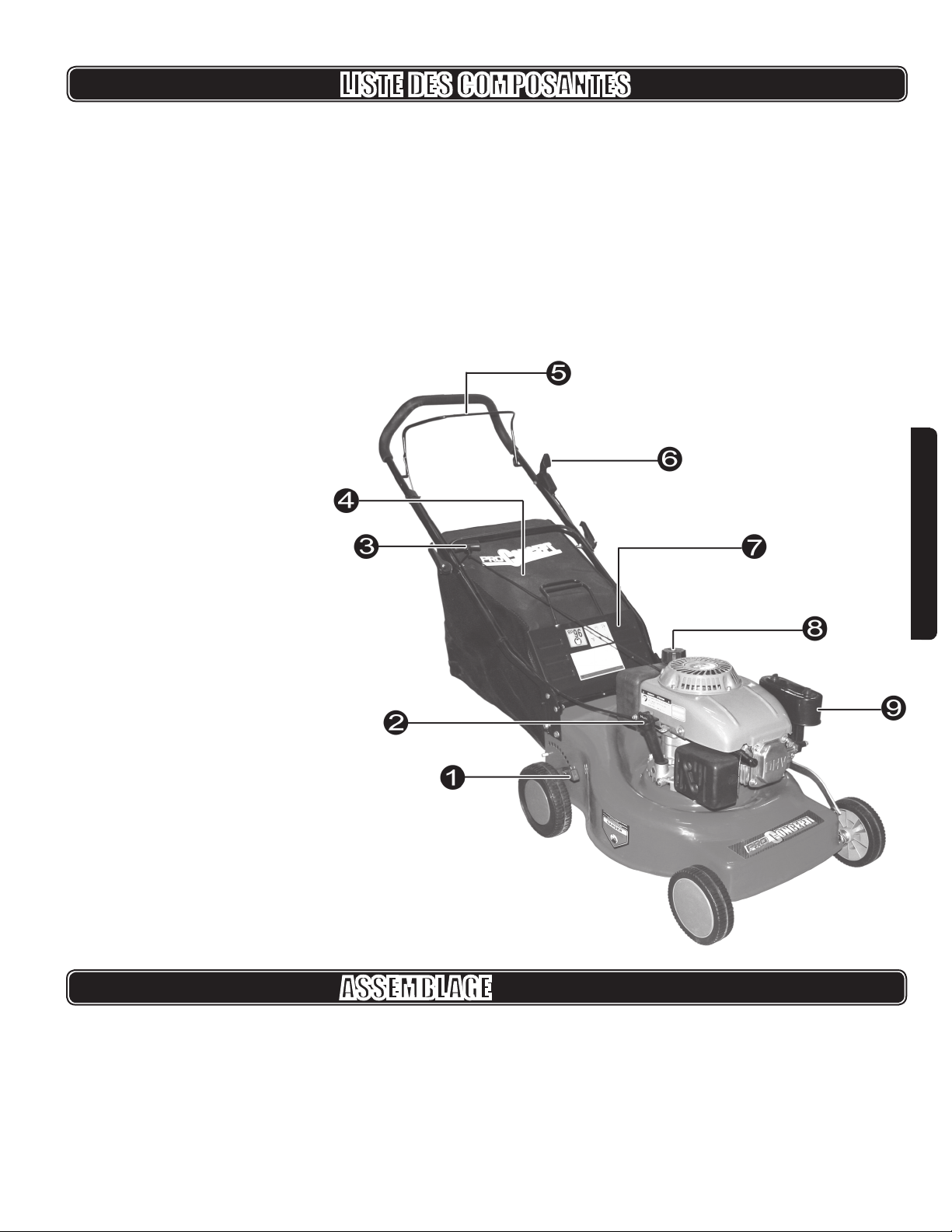
KNOW YOUR PRODUCT
ASSEMBLY
PACKAGE CONTENTS
135 cc Gas engine lawnmower
50 litre Grass catcher
Upper handle
2 x Handle wheel nuts and bolts
2 x Lower handle xing screws
1 x 600 ml SAE30 engine oil
1 x Double ended box spanner for spark plug and blade
2 x Cable ties
1. Height adjuster lever
2. Dipstick and oil ller
3. Starter grip
4. Grass bag
5. Operator presence control
6. Throttle trigger
7. Grass ap
8. Gas cap
9. Air lter
6 PLG375b
ENGLISH
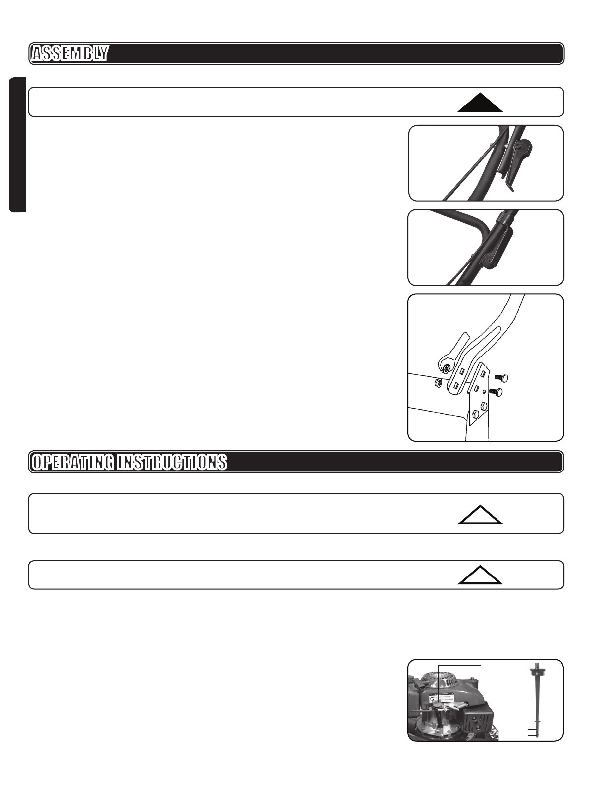
UNFOLDING THE HANDLE (Fig. 0 - 1)
WARNING: Folding or unfolding the handle improperly may cause serious
damage to the cables, causing an unsafe operating condition.
Do not damage the cables when folding or unfolding the handle.
1. Carefully move the upper handle up until the handle halves are in line and nest
with the lower handle bracket.
2. Once the handles brackets are in line, lock the handle locking lever.
ATTACHING THE LOWER HANDLE (Fig.2)
1. To attach the lower handle, use a wrench to remove the four bolts.
2. Place the lower handle in position and replace the four bolts. Use the wrench to
retighten the nuts.
FOLDING THE HANDLE
1. Release the locking handle lever.
2. Carefully fold the upper handle down towards the mower.
Fig. 1
ASSEMBLY
Fig. 0
!
OPERATING INSTRUCTIONS
BEFORE STARTING THE ENGINE
IMPORTANT:The following procedures and adjustments must be performed
BEFORE the engine is started. Do not attempt to make any of these
adjustment while the engines running.
FILLING THE OIL (Fig. 3)
IMPORTANT: The mower is supplied with no oil in the engine. It is essential that
oil be added before starting the engine for the rst time.
To add oil to the lawnmower:
1. Remove the warning label from under the dipstick.
2. Remove the dipstick and slowly pour 600 ml of SAE30 engine oil into the
engine via the oil ller.
3. Replace the dipstick and tighten.
Before each subsequent use, the oil level must be checked and if necessary
topped up with SAE30 engine oil.
1. With the lawnmower on level ground, unscrew and remove the oil lever
dipstick.
2. Wipe oil lever dipstick on a clean rag.
!
!
Fig. 3
Dipstick and
oil ller
Maximum
Minimum
Fig. 2

v.080227 7
ENGLISH
OPERATING INSTRUCTIONS
FILLING THE GASOLINE
WARNING: Gasoline is highly ammable and extreme precautions must be
taken when handling or working with it. Gasoline should only be stored in
approved containers. Never buy, or store more than 30 days supply of gasoline.
DO NOT mix oil with gasoline.
Clean the area around the gas ller cap before removing the cap. Remove the
warning label from under the gas cap. Always use fresh, clean, unleaded gasoline
and ll the tank using a clean funnel.
IMPORTANT: Always leave at least 13 mm below the bottom of the ller neck to
allow for expansion.
Clean up any overow or splashes of gas before starting the engine. Do not ll the
tank indoors, or in a poorly ventilated area. Gasoline fumes are inammable and
dangerous. Never open the ll cap, or ll the tank, if the engine is still hot after use.
Do not smoke when lling the tank, using the machine, or when gasoline is present
in the work area. Ensure that you securely tighten the ller cap after lling.
FITTING THE GRASS BOX (Fig. 5 - 6)
To t the grass box, lift the grass discharge ap and locate the grass box on the
hooks provided on the deck of the machine.
IMPORTANT: Always t the grass box before starting the engine.
IMPORTANT: Before emptying the grass box, or adjusting the cutting height,
ensure that the engine is switched off and the spark plug cap is disconnected.
!
!
!
Fig. 6
Grass Box
Mounted on
the Hook
Gas ller cap
Fig. 4
Grass box hooks
Fig. 5
3. Replace, but do not screw back in place, and remove again.
4. The oil level must be between the min and max marks on the dipstick.
5. If necessary, add oil pouring in slowly.
6. Replace the dipstick and tighten.
8 PLG375b
ENGLISH
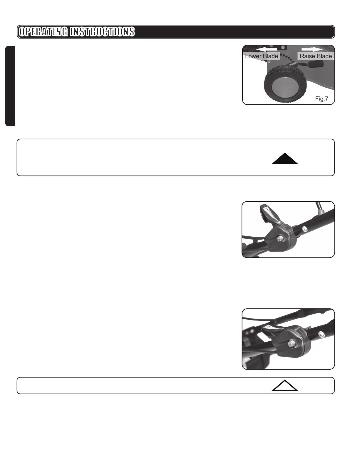
ADJUSTING THE CUTTING HEIGHT (Fig. 7)
To adjust the height, pull the adjuster towards the wheel to disengage from
the lug and rotate. To lower the blade, rotate the adjuster towards the rear of
the lawnmower. To raise the blade, rotate the adjuster towards the front of the
lawnmower. When making adjustments make sure that the adjuster ts over one of
the ve lugs.
STARTING THE ENGINE (Fig. 8 - 9)
WARNING: Do not operate the machine in closed or poorly ventilated areas as
the exhaust gases contain poisonous substances. Keep hands, feet, hair and
clothing away from all the moving parts of the machine. The exhaust and other
parts of the machine will become hot during use. Make sure that the blade is
securely fastened before starting the engine.
1. Before starting the engine, make sure that the spark plug cap is located on
the spark plug and that the machine is lled with sufcient oil and gasoline, as
described earlier in this manual.
2. To start the engine from cold, back off the throttle control lever (Fig. 8).
3. Grip the handle and hold down the operator presence control (OPC) bar with
your left hand.
4. With your right hand, slowly but rmly pull the starter handle and rope out until
resistance is felt.
5. Let the rope rewind slowly and then pull it with a rapid full arm stoke. If the
engine fails to start after three pulls, repeat the starting process as above.
6. The engine should now start. Allow the starting handle to recoil and gently
release back into the housing.
7. Once the engine is running, move the throttle control lever to its most forward
position, to a moderate speed that suits cutting conditions (Fig. 9).
IMPORTANT: To start a warm engine, leave the throttle control lever in its
position.
Fig. 8
Fig. 9
!
!
OPERATING INSTRUCTIONS

v.080227 9
ENGLISH
STOPPING THE ENGINE
To stop the engine, release the OPC bar.
WARNING: The blade will continue to rotate for a few seconds after the engine
has stopped. Disconnect the spark plug cap if the lawnmower is to be left
unattended.
!
USING THE LAWNMOWER
WARNING: Always observe the strictest safety procedures when using the
lawnmower. Carefully read the safety instructions of this manual before using.
Maintain the sharpness of the blade when cutting grass. If the blade has worn
excessively and become pitted and blunt, it should be replaced or sharpened.
When the blade is sharpened the balance of the blade must be maintained. Blade
sharpening should only be undertaken by qualied service personnel.
The sharpness of the blade will directly affect the performance of the lawnmower.
The best results will be achieved if the grass is dry. Wet grass will tend to clog the
blade and the grass collection system. Grass grows at different rates at different
times of the year. Never use the lowest cutting height for the rst cut of the season
or in drought conditions. Only about one third of the grass height should be cut. If
the grass to be cut is over six inches tall, use the highest cutting height. Then mow
at a lower setting for the best results.
If the lawnmower will not collect the cuttings efciently, the grass discharge chute
may be blocked, the grass box may be full, or the underside of the mower deck
may be clogged.
WARNING: Do not attempt to remove grass from the grass chute area while
the blade is rotating. Before clearing any blockages, or emptying the grass box,
make sure that the engine is switched off and the spark plug cap is disconnected
and moved away from the spark plug. The blade will continue to rotate for a few
seconds after the engine has stopped.
REMOVING AND REFITTING THE BLADE
WARNING: Before removing or retting the blade, ensure that the engine is
switched off and the spark plug cap is disconnected and moved away from the
spark plug.
To remove the blade:
1. Grip the end of the blade using a thickly padded glove or rag.
2. Use the 17 mm box spanner provided to remove the blade bolt, washer and
blade.
To t a new or re-sharpened blade:
1. Locate the two holes in the blade.
2. Align the holes of the blade with the two studs on the blade ange.
3. Replace the washer and bolt. Make sure that the blade is correctly located.
4. Secure and fully tighten bolt.
5. Conrm blade is secure and replace spark plug cap.
!
!
OPERATING INSTRUCTIONS
!

10 PLG375b
ENGLISH
MAINTENANCE
Before starting any cleaning or maintenance routines on the lawnmower, conrm
that the engine is switched off and the spark plug cap is disconnected and moved
away from the spark plug.
CLEANING
To ensure the best performance from your lawnmower, it is important to keep it
clean. Always clean your lawnmower immediately after use. Do not allow grass
cuttings and other debris to become dry and hard on any of the lawnmower
surfaces. This will directly affect the cutting and grass collection performance.
Make sure that the underside of the lawnmower deck is cleaned and clear of all
grass cuttings. Ensure that the grass discharge chute and grass discharge ap are
clean and clear. The grass box must always be emptied after use and the interior
cleaned and cleared of all grass cuttings. Make sure that the exterior of the engine
is clear of all clippings, cuttings, and dirt.
GENERAL MAINTENANCE
Make sure that all nuts, bolts and screws are kept tight and secure. Always have
any damaged or worn parts repaired or replaced. Check the blade and the engine
mounting bolts at regular intervals. The front and rear wheel spindles should
be lubricated periodically with light lubricating oil. Always have your lawnmower
inspected and maintained by a qualied service facility. The engine and its
components should be regularly serviced by qualied personnel.
MAINTENANCE SCHEDULE
12 Hours of Use
Air lter Clean
Spark plug Not applicable
Engine oil Check
24 Hours of Use
Air lter Clean
Spark plug Clean
Engine oil Replace
36 Hours of Use
Air lter Clean
Spark plug Clean
Engine oil Check

v.080227 11
ENGLISH
!
SPARK PLUG (FIG. 10)
1. Once the engine has cooled, remove the spark plug using the box spanner
supplied.
2. Clean the plug with a wire brush.
3. Using a feeler gauge (not included) set the gap to 0.75 mm (0.030”).
4. Ret the spark plug taking care not to over-tighten.
Fig. 10
AIR FILTER
1. Unclip the air lter cover and remove the sponge lter element.
2. To avoid objects falling into the air intake, replace the air lter cover.
3. Wash the lter element in warm soapy water.
4. Rinse and allow lter element to dry naturally.
IMPORTANT: Never run the engine without the air lter element installed.
CHANGING THE OIL (Fig. 11)
The oil drain plug is located under the oil lter as shown.
1. Tilt the lawnmower towards the ller, have a container ready to catch the oil.
2. Remove the oil drain plug.
3. Once the oil has been emptied, replace the oil drain plug making sure that the
washer is in place.
4. Wipe clean any spillages.
5. Rell with 600 ml of SAE30 oil.
6. When the dipstick is rested on the ller pipe (i.e. not screwed in place), the oil
level must be between the min and max marks on the Dipstick. See “Filling
with Oil” on Page 6.
7. Do not overll.
8. Start the engine and allow it to run briey.
9. Stop the engine, wait a minute and check oil level.
10. Top up if necessary.
STORAGE
WARNING: Gasoline left in the fuel tank over the winter period will become stale
and the engine will not start.
For long term storage and at the end of the season, the gas tank should be
drained. To drain the gas tank:
1. On the last refueling of the year, add fuel stabilizer to the fuel as directed by the
engine manufacturer.
2. Start the mower and run until it stops.
3. Try restarting the mower. If the mower does not start, the engine is dry.
IMPORTANT: Do not store gasoline for long periods of time. Dispose of excess
gasoline in an environmentally safe way. Your recycling centre can advise
you on the best method of disposal. Make sure that the lawnmower has been
thoroughly cleaned before storing it in a clean dry place.
Fig. 11
Oil Drain Plug
MAINTENANCE
If your tool requires service, ask your retailer or call us at 1-888-267-7713 for an
authorized repair centre in your area.
!
!
!

12 PLG375b
ENGLISH
GENERAL PARTS LIST
Please refer to the mower schematic drawing on page 30.
NO. DESCRIPTION QTY.
1 Bolt 3/8" - 24 UNF 1
2 Cutter bar blade washer 1
3 Blade 1
4 Clip (left) 1
5 Crankshaft key 1
6 Blade mounting boss 1
7 Front axle bush 2
8 Clip (right) 1
9 Front axle assembly 1
10 Front wheel 2
11 Curved spring washer 4
12 Washer 4
13 Circlip 12 4
14 Front hub cap 2
15 Rear hub cap 2
16 Rear wheel 2
17 Rear axle assembly 1
18 Down x board 2
19 Screw ST4.8 x 16 9
20 Connecting bar 1
21 Pin 2 x 16 2
22 Up x board 2
23 Bolt (M8 x 40) 3
24 Washer 3
25 Height adjustment handle 1
26 Mower base 1
27 Nut (M8) 12
28 Fix pillar 1
29 Connecting bar spring 1
30 E ring 6 2
31 Flap rod 1
32 Flap spring 1
NO. DESCRIPTION QTY.
33 Bolt (M8 x 16) 4
34 Washer 8 4
35 Left bracket 1
36 Rivet (4 x 12) 3
37 Discharge opening inll piece 1
38 Nut 1
39 Pillar 1
40 Washer 1
41 IP60 motor Assembly 1
42 Right bracket 1
43 Bolt (M8 x 19) 4
44 Seal strip 1
45 Rubber strip 1
46 Handle pivot bolt 2
47 Nut 2
48 Rear discharge ap 1
49 Nut 2
50 Handle bar knob 2
51 Bolt 2
52 Brake cable 1
53 Lower handle bar 1
54 Upper handle bar 1
55 Rubber tube 1
56 Brake bar 1
57 Nut M6 1
58 Throttle control 1
59 Washer 6 1
60 Bolt (M6, A3) 1
61 Washer 2
62 Grass bag frame 1
63 Grass bag 1
64 Clip 2

v.080227 13
ENGLISH
MOTOR PARTS LIST
Please refer to the motor assembly schematic drawing on page 31.
NO. DESCRIPTION QTY.
1 Piston compression ring 1 1
2 Piston compression ring 2 1
3,4,5 Oil ring assy.
3 Oil ring 3 2
4 Oil ring 2 1
5 Oil ring 1 1
6 Piston 1
7 Wrist pin circlips 2
8 Wrist pin 1
9,37,38 Connecting rod assy. 1
9 Connecting rod 1
37 Connecting rod cap 1
38 Connecting rod bolt 1
10-15 Oil ller assembly 1
10 Dipstick 1
11 Bolt M6 x 45 1
12 O-ring 1
13 Filler tube 1
14 Oil ller bracket 1
15 O-ring 1
16 Pin 8 x 14 2
19 Washer 1
20 Screw stopper 1
21 Bolt M6 x 30 5
22 Bolt M6 x 25 2
23 Seal washer D25 x 38 x 7 1
25 Shutter 1
26 Bolt M6 x 10 1
28 Gear shaft 1
29 Retainer ring 6 for shaft 1
30 Gear assembly 1
27 Cover 1
31 Washer 6 2
32 Cylinder gasket 1
33 Nylon camshaft 1
34 Valve tappet 2
36 Crankshaft 1
39 Woodruff key 1
35 Small gear 1
41 Liner 2 (L=12) 1
42 Liner 1 (L=21) 1
43 Bracket 1
NO. DESCRIPTION QTY.
44 Heat shield 1
46 Bolt M6 x 25 1
47 Vent pipe 1
48 Spring holder 1
49 Speed adjustment lever 1
50 Speed adjustment spring 1
51 Seal washer D6 x 11 x 4 1
52 Spring pin 1
53 Bolt 1
54 Rocker assembly 1
56 Hose clamp B 1
57 Hose 1
58 Hose clamp A 1
60 Bolt M8 x 55 1
61 Washer 8 x 35 1
62 Damping washer 2
Tank assembly 1
59 Gasoline lter screen 1
63 Fuel cap assembly 1
64 Tank body 1
65 Heat shield 1
66 Bolt M6 x 16 2
Flameout cable assembly 1
67 Flameout cable 1
68 Filter screen 1
69 Ventilation sealed washer 1
70 Ventilation ap 1
Ventilation cover assembly 1
71 Ventilation cover 1
72 Bolt M6 x 12 2
73 Bearing 6205 1
74 Seal washer D22 x 35 x 7 2
Flywheel assembly 1
75 Cast iron ywheel 1
76 Fan 1
77 Recoil disc 1
78 Tamper-proof nut M14 x 1.5 1
79 Bolt M6 x 10 1
80 Starter housing assembly 1
81 Shroud 1
82 Bolt M6 x 8 4
85 Flameout switch assembly 1

14 PLG375b
ENGLISH
All products distributed by Airco Superior Clarke are warranted against
manufacturers’ faults and defects for a period of one year from the date of
purchase by the end user. The Company will REPAIR OR REPLACE, AT ITS
OWN OPTION, merchandise deemed by the company to be defective, provided
that is has not been misused, abused, altered, or repaired by anyone other than an
authorized repair centre. Retain proof of purchase. Return the defective product to
the place of purchase.
This warranty does not extend to parts deemed consumables, such as brad and
staple gun driver blades, grinding discs, welding contact tips, etc. All warranty
claims must have prior authorization and must be shipped prepaid to the
Richmond, BC or Mississauga, ON warehouses, or an authorized repair depot,
accompanied by a copy of the invoice specifying the date that the item was sold
to the end user. You should take any tool with a problem back to where you
purchased it, accompanied by your receipt.
WARRANTY
MOTOR PARTS LIST
Please refer to the motor schematic drawing on page 31.
NO. DESCRIPTION QTY.
86 Bolt M6 x 16 1
88 Brake assembly 1
89 Bolt M6 x 10 1
90 Bolt M6 x 25 2
91 Ignition assembly 1
92 Liner 2
Crankcase asembly
24 Crankcase 1
93 Cylinder 1
94 Seal 1
95 Orientation Pin 10 x 16 2
96 Exhaust valve 1
97 Intake valve 1
98-105 Air-lter assembly 1
98 Filter retention screw 1
99 Air-lter cover 1
100 Screen 1
101 Filter core 1
102 U-ring 1
103 M6 Nut 2
104 Air-lter base 1
105 Air-lter seal 1
106 Carburetor assembly 1
107 Throttle linkage 1
NO. DESCRIPTION QTY.
108 Throttle spring 1
109 Seal 1
110 Intake pipe 1
111 Seal 1
112 Stud AM6 x 95 2
113 Cylinder head 1
114 Stud AM6 x 80 2
115 Spart plug F6RTC 1
116 Mufer gasket 1
117 Mufer assembly 1
118 Mufer shield 1
119 Nut M6 2
120 Bolt M8 x 45 4
121 Push rod 2
122 Bracket 1
123 Valve spring 2
124 Spring base 2
124 Adjustment screw 2
125 Bolt 2
126 Valve rocker 2
127 Bolt M6 x 0.5 2
128 Bolt M6 x 0.5 2
129 Valve cover gasket 1
130 Valve cover 1
131 Bolt M6 x 16 2
132 Bolt M6 x 12 2
IMPORTANT: Our products are continually monitored to comply with changing
technical standards and requirements. The company reserves the right to alter
design and specications without prior notice. !

v.080227 15
FRANÇAIS
DESCRIPTION DES SYMBOLES
!
!
Ce mode d’emploi et de produit contient des alertes en matière de sécurité ainsi
que des messages utiles et informatifs précédés de symboles ou de mots-clés.
Voici l’explication de ces symboles et mots-clés et de ce qu’ils représentent.
Ce symbole, accompagné du mot AVERTISSEMENT attire votre attention sur un
geste ou une condition pouvant entraîner des blessures sérieuses à l’utilisateur ou
aux observateurs.
Ce symbole, accompagné du mot IMPORTANT, offre l’information nécessaire à la
protection de l’appareil ou de l’opérateur.
Ce symbole informe l’opérateur qu’il doit lire le manuel d’instructions avant
d’utiliser l’appareil.
Ce symbole rappelle à l’opérateur de porter des protecteurs oculaires, auditifs et
de tête lorsqu’il utilise un outil électrique.
Surface chaude.
Position d’étrangleur « Démarrage à froid » (étrangleur fermé).
Position d’étrangleur « Démarrage à chaud » (étrangleur ouvert).
Produit conforme à la réglementation de l’Environmental Protection Agency des
États-Unis.
Pour employer cet outil comme il se doit, vous devez respecter les règlements de
sécurité, les directives d’assemblage et les consignes d’utilisation que renferme le
présent manuel. Quiconque se sert de cet outil ou en fait l’entretien doit connaître
les risques éventuels liés à sa manipulation et avoir pris connaissance de ce
manuel. Les enfants et les personnes atteintes d’incapacité ne doivent pas utiliser
cet outil. On doit en tout temps surveiller les enfants qui se trouvent dans l’aire
d’utilisation de l’outil. Vous êtes également tenu d’observer les règlements de
prévention des accidents en vigueur dans votre région. Cela vaut également pour
les règles générales en matière de santé et sécurité au travail.
AVERTISSEMENT : Certaines consignes de sécurité de base doivent toujours
être respectées lors de l’utilisation d’un appareil à essence an de réduire les
risques de blessure ou de dommage. Avant d’employer ce produit, lisez tous
les avertissements et instructions. Conservez ce manuel d’instructions pour
référence future.
!
IMPORTANTE DIRECTIVES DE SÉCURITÉ

16 PLG375b
FRANÇAIS
IMPORTANTE DIRECTIVES DE SÉCURITÉ
1. UTILISEZ LE BON OUTIL POUR LA BONNE TÂCHE. N’utilisez jamais cet
outil pour une n pour laquelle il n’a pas été conçu.
2. PORTEZ DES VÊTEMENTS APPROPRIÉS. Portez des vêtements de
travail solides et ajustés qui offrent de la protection, tels une salopette ou des
pantalons, des chaussures et des gants de sécurité. Si vous avez les cheveux
longs, portez un couvre-chef de protection.
3. PORTEZ DE L’ÉQUIPEMENT DE PROTECTION. En tout temps lors de
l’utilisation de cet appareil, vous devriez porter des gants de travail de
qualité industrielle, un casque de protection, une visière de protection ou des
protecteurs oculaires ainsi que des bouchons pour oreilles de bonne qualité ou
d’autres protecteurs auditifs.
4. RANGEZ CET APPAREIL DANS UN ENDROIT SÛR. Ouvrez lentement le
capuchon de carburant an de libérer toute pression du réservoir de carburant.
An d’éviter les risques d’incendie, éloignez-vous à au moins 10 pieds (3
mètres) de la zone de remplissage de carburant avant de démarrer l’outil.
5. NE DÉMARREZ NI N’UTILISEZ JAMAIS LA MACHINE À L’INTÉRIEUR
D’UNE PIÈCE OU D’UN IMMEUBLE FERMÉ. Les fumées de l’échappement
contiennent du monoxyde de carbone dangereux.
6. TENEZ LES SPECTATEURS, LES ENFANTS ET LES ANIMAUX À UNE
DISTANCE DE 50 PIEDS (15 MÈTRES). S’ils s’approchent, éteignez
immédiatement l’appareil. L’utilisation d’équipement électrique doit toujours
être réservé aux personnes matures et disposant des connaissances
nécessaires.
7. GARDEZ TOUTES LES PARTIES DE VOTRE CORPS LOIN DE TOUTE
PIÈCE EN MOUVEMENT.
8. N’UTILISEZ PAS L’APPAREIL EN POSITION PEU MANIABLE. Gardez vos
pieds au sol et conservez votre équilibre en tout temps. Ne vous étirez pas
trop.
9. SOYEZ VIGILANT. Portez attention à ce que vous faites. Utilisez le gros bon
sens. Ne faites fonctionner aucun outil électrique lorsque vous êtes fatigué,
que avez bu ou consommé des drogues ou médicaments.
10. SOYEZ TOUJOURS CONSCIENT DE VOTRE ENVIRONNEMENT. Soyez à
l’affût des risques potentiels que vous pourriez ne pas entendre à cause du
bruit de l’appareil.
11. MAINTENEZ TOUTES LES VIS ET LES AGRAFES BIEN SERRÉES. Ne
faites jamais fonctionner cet appareil s’il est incorrectement réglé ou s’il n’est
pas complètement assemblé de façon sécuritaire.
12. VÉRIFIEZ L’ABSENCE DE DOMMAGE SUR LES PIÈCES. Avant d’utiliser cet
outil, toute pièce ou garde endommagé doit être vérié avec soin an d’établir
si l’appareil peut fonctionner correctement et accomplir la tâche pour laquelle
il a été conçu. Vériez l’alignement et le mouvement libre des pièces mobiles,
l’absence de bris, l’assemblage adéquat ainsi que l’absence de tout autre
facteur qui puisse affecter le fonctionnement de l’appareil. Une pièce ou un
garde endommagé doit être réparé ou remplacé correctement par un centre
de service autorisé, à moins d’une indication contraire gurant ailleurs dans ce
mode d’emploi.
13. FAITES REMPLACER TOUT INTERRUPTEUR DÉFECTUEUX PAR UN
CENTRE DE SERVICE AUTORISÉ. N’utilisez pas l’outil électrique si son
interrupteur ne permet pas de le mettre en marche ou de l’éteindre.
14. N’UTILISEZ QUE DES PIÈCES DE APPROUVÉES. N’utilisez que des pièces
de rechange identiques. Faites appel à un centre de service agréé pour
remplacer les pièces.
15. RANGEZ L’ÉQUIPEMENT LOIN DE TOUT MATÉRIAU POTENTIELLEMENT
INFLAMMABLE, tel un chauffe-eau ou un sèche-linge à gaz, une fournaise à
huile, un radiateur portatif, etc.

v.080227 17
FRANÇAIS
IMPORTANTE DIRECTIVES DE SÉCURITÉ
AVERTISSEMENT : Des rapports font état du fait que les vibrations d’outils à
main peuvent contribuer à une maladie nommée « Syndrome de Raynaud »
chez certaines personnes. Les symptômes peuvent comprendre le picotement,
l’engourdissement et le blanchiment des doigts, en général apparents après
une exposition au froid. Les recherches indiquent que les facteurs héréditaires,
l’exposition au froid et à l’humidité, la diète, le tabagisme et les pratiques de
travail pourraient contribuer à l’apparition de ces symptômes. L’état de la
science ne permet pas de savoir si des vibrations ou une exposition prolongée
puissent contribuer à la maladie. Certaines mesures peuvent être prises par
l’opérateur an de potentiellement réduire les effets de la vibration :
Gardez votre corps chaud, particulièrement au niveau de la tête, du cou, des
pieds, des chevilles, des mains et des poignets.
Maintenez une bonne circulation sanguine en exécutant des exercices
vigoureux des bras pendant des pauses fréquentes et en évitant de fumer.
Limitez les heures de travail avec l’appareil. Tentez de remplir chaque journée
de tâches ne nécessitant pas l’utilisation d’outil ou autre équipement électrique
à main.
Portez des gants. Les gants aident à réduire la transmission de la vibration de
la machine vers vos mains.
IMPORTANT : Si vous ressentez un inconfort ou que vous remarquez une
rougeur et une enure de vos doigts suivies par un blanchiment et une perte de
sensation, consultez votre médecin avant de vous exposer à nouveau au froid et
à la vibration.
!
!
Arrêtez toujours le moteur et retirez le protecteur de bougie d’allumage avant
de nettoyer ou de transporter l’appareil, avant d’effectuer des réglages et avant
de laisser l’appareil sans supervision.
Ne tentez jamais d’enlever l’herbe de la goulotte d’herbe arrière si la lame est
en train de tourner. Arrêtez le moteur et retirez la bougie d’allumage.
Cette tondeuse devrait être utilisée exclusivement pour tondre les pelouses.
N’utilisez pas la tondeuse à gazon pour toute autre tâche.
Avant d’utiliser la tondeuse, assurez-vous qu’il n’y a aucun obstacle ni objet
étranger dans la zone de travail.
Portez toujours des souliers antidérapants, des gants, des lunettes de
protection, un casque, des protecteurs d’oreilles et des pantalons longs en
utilisant cette tondeuse à gazon.
Assurez-vous que la lame de la tondeuse est bien xée avant de démarrer le
moteur.
Vidangez toujours le réservoir d’essence avant d’incliner la tondeuse à
gazon sur le côté. Inclinez seulement la tondeuse sur le côté avec la sortie
d’échappement située près du sol. N’inclinez la tondeuse que pour une courte
période de temps an d’éviter la fuite d’huile dans des espaces inappropriés
du moteur.
Déplacez la tondeuse à travers la surface d’une pente, non pas du haut en
bas. Faites attention à vos pas. N’utilisez pas la tondeuse à gazon sur des
pentes ayant une inclinaison excessive.
Toujours marcher et ne jamais courir avec la tondeuse à gazon.
La sortie d’échappement et certaines autres pièces de la tondeuse deviendront
chaudes lors de l’usage.
N’inclinez jamais la tondeuse et ne la faites pas passer sur des surfaces autres
que les pelouses lorsque le moteur tourne.
Ne placez jamais les mains ou les pieds sous le châssis de la tondeuse
lorsque la lame tourne.
N’utilisez pas la tondeuse sans la boîte à herbe.
RÈGLES DE SÉCURITÉ ADDITIONNELLES POUR TONDEUSE AUTOPROPULSÉE

18 PLG375b
FRANÇAIS
Il est possible que des pierres ou d’autres objets soient projetés par la
tondeuse. Assurez-vous toujours que toute autre personne, les enfants et les
animaux de compagnie soient éloignés à une distance sécuritaire,
soit 15 m (50 pi).
Utilisez toujours de l’essence sans plomb fraîche et propre et servez-vous d’un
entonnoir propre pour remplir le réservoir. Ne remplissez jamais le réservoir
jusqu’au rebord. Nettoyez tout déversements ou éclaboussures d’essence
avant de démarrer le moteur.
Ne remplissez pas le réservoir et ne démarrez pas la tondeuse à gazon à
l’intérieur ni dans un endroit sans aération adéquate. Les vapeurs d’essence
sont inammables et dangereux. N’ouvrez jamais le bouchon du goulot de
remplissage et ne versez jamais de l’essence dans le réservoir si le moteur est
toujours chaud après l’usage.
Ne pas fumer en remplissant le réservoir, en utilisant la tondeuse, ni lorsqu’il y
a de l’essence à proximité dans la zone de travail.
Assurez-vous que le bouchon du goulot de remplissage est bien fermé après le
remplissage.
RÈGLES DE SÉCURITÉ ADDITIONNELLES POUR TONDEUSE AUTOPROPULSÉE
SPÉCIFICATIONS
Moteur : Moteur avec valve en tête de 135 cc
Évacuation : Arrière / déchiquetage
Volume du sac arrière : 50 L
Diamètre de coupe : 450 mm (18 po)
Hauteur de coupe adjustablet : 16 à 76mm (0,63-3,00 po)
Nombre de hauteur de coupe : 10
Capacité du réservoir de essence : 1,1 L
Capacité du réservoir d’huile : 0,6 L
Largeur du bloc de coupe: 508 mm (20”)
Poids : 30 kg (66,1 lb.)
v.080227 19
FRANÇAIS
LISTE DES COMPOSANTES
Tondeuse à gazon avec moteur à essence de 135 cc
Bac à herbe de 50 litres
Poignée supérieure
2 écrous manuels et boulons de poignée
2 vis de xation de poignée inférieure
1 clé à douille double pour la bougie d’allumage et la lame
2 attaches de câble
ASSEMBLAGE
1. Levier de réglage de hauteur
2. Jauge d’huile et goulot de remplissage
3. Poignée de démarrage
4. Boîte à herbe
5. Commande de présence de l’opérateur
6. Tringlerie de commande du papillon des gaz
7. Rabat de décharge d’herbe
8. Bouchon de remplissage d’essence
9. Filtre à air

20 PLG375b
FRANÇAIS
DÉPLOIMENT DE LA POIGNÉE (Fig. 0 - 1)
AVERTISSEMENT : Plier ou déployer la poignée incorrectement peut
endommager les câbles, causant un mauvais fonctionnement du système de
cables
N’endommagez pas les câbles en pliant ou en dépliant la poignée.
1. Relevez soigneusement la poignée supérieure jusqu’à ce que les moitiés de
poignée soient en ligne avec la partie inférieure de poignée.
2. Une fois que les deux parties de poignées sont alignées, fermez le levier de
blocage de poignée
ASSEMBLAGE DE LA PARTIE INFÉRIEUR DES POIGNÉES (FIG.2)
1. Pour assembler la partie inférieur de la poignée, dévisez les boulons.
2. Placer la partie inférieur de la poignée en position et boulonnez en place en
serrant bien.
PLIER LA POIGNÉE
1. Libérez le levier de fermeture de poignée.
2. Pliez soigneusement la poignée supérieure vers le bas vers la tondeuse.
Fig. 1
ASSEMBLAGE
Fig. 0
!
AVANT DE DÉMARRER LE MOTEUR
IMPORTANT : Les procédures et réglages suivants doivent être effectués
AVANT de démarrer le moteur. Ne tentez pas d’effectuer ces réglages pendant
que le moteur tourne.
REMPLISSAGE D’HUILE (FIG. 3)
IMPORTANT : La tondeuse à gazon est vendue sans huile dans le moteur. Il
est essential que d’huile soit versée dans le réservoir avant de démarrer le
moteur pour la première fois.
Pour verser de l’huile dans la tondeuse à gazon :
1. Retirez l’étiquette d’avertissement située sous la jauge d’huile.
2. Retirez la jauge d’huile et versez lentement 600 ml d’huile à moteur SAE30
dans le goulot de remplissage du moteur.
3. Remettez en place la jauge d’huile et serrez-la.
Avant chaque usage, il faut vérier le niveau d’huile et ajouter de l’huile à moteur
SAE30 au besoin.
1. Avec la tondeuse située sur une surface de niveau, dévissez et retirez la jauge
d’huile.
!
!
Fig. 3
Jauge d’huile
et goulot de
remplissage
Maximum
Minimum
CONSIGNES D’UTILISATION
Fig. 2
Table of contents
Languages:


