4
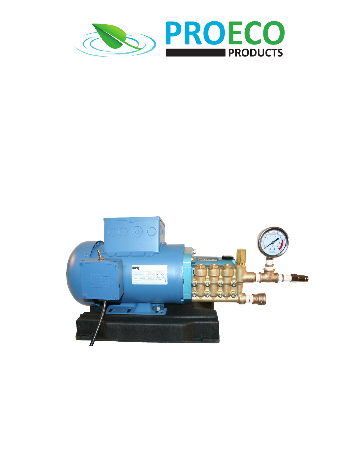
Misng Pump Assembly Instrucons
Limited Warranty
This PROECO PRODUCT is covered by a 2-year limited warranty by PROECO PRODUCTS. The limited warranty period begins from the date of purchase and covers material and manufacturing defects or failure of the
product to operate as specied by PROECO PRODUCTS during the duraon of the limited warranty period.
This limited warranty does not cover failure or problems related to:
− Improper installaon, see this manual for proper installaon procedures.
− Modicaon of the product in any way including aempts to repair the product by someone other than a PROECO PRODUCTS trained and authorized repair technician.
− Failure to follow proper safety, care and maintenance guidelines as outlined in this manual.
It also does not cover those parts of the product that are subject to normal wear and tear during usage of the product, such as:
− Impellers on pumps
− Filter pads and lter medium in lters
− Lamps in lights and UV clariers
PROECO PRODUCTS's sole liability shall be to replace or repair the product covered by this limited warranty. PROECO PRODUCTS shall not be liable for any consequenal damage to any other part of the water garden,
pond, water feature, landscape, structure, or the contents of any structure where the product is located or used including no liability for damage or harm to sh, animals, or plants in or around the water garden, pond or
water feature.
THE EXPRESS WARRANTIES SET FORTH HEREIN ARE THE ONLY WARRANTIES WITH RESPECT TO THE PRODUCTS, AND THE REMEDIES SET FORTH HEREIN ARE THE EXCLUSIVE REMEDIES IN THE EVENT OF A BREACH OF
SUCH WARRANTIES. PROECO PRODUCTS EXPRESSLY DISCLAIMS ANY IMPLIED WARRANTY OF MERCHANTABILITY OR FITNESS FOR A PARTICULAR PURPOSE. PROECO PRODUCTS SHALL NOT BE LIABLE UNDER ANY
CIRCUMSTANCES FOR INCIDENTAL OR CONSEQUENTIAL DAMAGES OF ANY NATURE, FOR ANY BREACH OF SUCH WARRANTIES OR OTHERWISE. Some states do not allow the exclusion or limitaon of incidental or conse-
quenal damages, to the above limitaon may not apply to you.
Should your PROECO PRODUCTS product be defecve or fail under the terms of this limited warranty, you should return the product to your PROECO PRODUCTS dealer, along with your original receipt of purchase and
any other limited warranty documentaon you have, for replacement or repair. Should you have any queson about this limited warranty, please contact PROECO PRODUCTS at info@proecoproducts.com
Nozzle Part Number 1006 1008 1012 1015
Minimum & maximum number of
nozzles by size of pump Min. Max. Min. Max. Min. Max. Min. Max.
.5 gpm pump (1050) 5 14 4 12 3 8 4 6
1 gpm pump (1051) 10 28 8 23 619 4 13
1.5 gpm pump (1052) 26 76 21 62 16 47 12 34
2 gpm pump (1053) 42 125 35 102 26 76 19 55
Patio
Misting
Pump
Pool
NOZZLE SELECTION CHART
MISTING DESIGN EXAMPLE
1050 1051 1052 1053
GPM .5 1 1.5 2
Horsepower (HP) 1/2 1 1 1/2 2
Power Rang (amps) (120V / 240V) 7 14 / 6.4 17.4 / 7.8 17.4 / 7.8
Voltage Rangs * 120 V 120 V / 240 V 120 V / 240 V 120 V / 240 V
Voltage conguraon as shipped from factory 120 V 120 V 240 V 240 V
Power Cable Length () 6 6 6 6
Dimensions (in) 10 x 22 x10 10 x 22 x10 10 x 22 x10 10 x 22 x10
Warranty 2 Years 2 Years 2 Years 2 Years
MISTING PUMP SPECIFICATIONS
* Models 1051, 1052 and 1053 can be operated with either 120V or 240V. Model 1051 is congured as 120V and Models 1052 & 1053 are congured as 240V when
shipped from the factory. Instrucons for changing the voltage conguraon in the eld is included with the motors.