PROIETTA ARCHILED RGBW 12x20 User manual

!
!
INSTRUCTION MANUAL"
"
ARCHILED RGBW 12x20
WARNING:"
Read this instruction manual carefully before using the
projector !
Thank you for choosing a PROIETTA product#

INDEX
!
•SAFETY INFORMATION !
•TECHNICAL SPECIFICATIONS!
•INTRODUCTION"
1.1. PRODUCT FEATURES"
1.2. QUICK START!
•MODE OF OPERATION"
2.1. MAIN MENU"
2.1.1. BASIC USAGE"
2.1.2. KEYPAD LOCK"
2.2. MENU STRUCTURE"
2.3. MENU DESCRIPTION"
2.3.1. STATIC MODE (STAT) "
2.3.2. AUTO MODE (AUTO) "
2.3.3. DMX AND SLAVE (RUN) "
2.3.4. DMX ADDRESS (AddR) "
2.3.5. DMX512 CHANNEL MODE (PERS) "
2.3.6. ID ADDRESS CODE (Id) "
2.3.7. WORKING TEMPERATURE (TEMP) "
2.3.8. SCENE EDITING (EdiT) "
2.3.9. NATIVE SETTING (SET) "
2.3.10. WHITE BALANCE SETTING (CAL1) "
2.3.11. COLOR CORRECTION SETTING (CAL2) "
2.3.12. KEY PROTECTION SETTING (KEY)"
2.4. DMX CONSOLE OPERATION"
1!
2!
3!
3!
4!
5!
5!
5!
5!
6!
12!
12!
13!
14!
15!
15!
16!
16!
17!
18!
19!
20!
20!
21!

2.4.1. CHANNEL TABLE"
2.4.2. COLOR CHANGING TABLE"
2.4.3. DIMMING SPEED TABLE!
•DEFAULT CUSTOM PROGRAMS!
•WARRANTY!
•DECLARATION OF CONFORMITY!
•DISPOSAL OF UNUSED PRODUCT"
!
2
21!
26!
26!
27!
30!
31!
31!

SAFETY INFORMATION
Read the following security information carefully before performing any operation. The
product described in this manual is a lighting fixture for projecting a light beam into
outdoor environments.!
"
Any other use is not provided by the manufacturer and therefore relieves him of any
liability for damages arising from misuse. !
Always disconnect the projector from the outlet before any operation because of the risk
of electric shock if disassembling the projector or some of its parts. Any repairs must be
carried out solely by the manufacturer, who denies any responsibility for unauthorised
interventions. !
For reliable operation of the device, the ambient temperature must be between -25°C
(-13°F) and 45°C (113°F). !
Do not place objects on the power cable and in case of damage return the product to the
manufacturer for replacement in order to avoid dangers of electrocution. !
Do not look at the beam of light to avoid damaging your eyes.!
"
Never place the projector on flammable and/or combustible surfaces. !
Never touch the projector or its components with wet hands. !
1

TECHNICAL SPECIFICATIONS
MODEL
ARCHILED RGBW 12x20
POWER SUPPLY
SUPPLY VOLTAGE
AC 100-240 V
ELECTRICAL FREQUENCY
47-63 Hz
LED
12 LED RGBW 4-in-1
POWER CONSUMPTION
200 W max (R: 100%, G: 100%, B: 100%, W: 100%)
NUMBER OF COLORS
16.700.000
LIFETIME
30.000 h
CONTROLS
4 buttons menu (4-digit display); DMX 512; Master/Slave
IP (Protection rating)
IP66
MINIMUM AMBIENT TEMPERATURE
-25 °C
MAXIMUM AMBIENT TEMPERATURE
45 °C
WEIGHT:
7 Kg
DIMENSIONS:
See the drawings below (dimensions in mm)
2

INTRODUCTION
1.1 PRODUCT FEATURES
OPERATING MODES:
1. External Control Mode!
!
- DMX512 control (ten different DMX channel modes available);"
"
- Master-Slave control to operate with multiple units in daisy-chain programming only
one fixture as master unit.!
2. Standalone Mode
!
- Auto Mode (built-in and custom programs, see page 13): !
"
- ten built-in sequences (AT.01-AT.10) color-pulse (alternating colors
fading to black), color-fade (gradient between colors) and strobe effects
with or without varying speed (strobe function is also available in
external control mode, depending on chosen DMX channel mode, or
Static Mode);!
"
- internal programming function to edit ten custom automatic mode
programs (PR.01-PR.10): up to thirty scenes per program with different
color, length and fade time (program data can be exchanged between
different units, see page 18).!
- Static Mode (custom color static scene, see page 12):!
"
- a static scene can be set to let the the user quickly select any fixed
color without the use of the console (and eventually assign the strobe
effect setting its speed).!
3

1.2 QUICK START
SETTING UP OPERATING MODE:
The fixture normally runs in "External Control" Mode, therefore converting into colors any
DMX received value, unless "Automatic" Mode, "Static" Mode, or "Slave" Mode is
selected. !
In this case the unit will wait to receive an external DMX signal on the selected address,
and will not emit any light until this happens.!
In order to avoid this, the fixtures are preprogrammed to automatic mode before to be
shipped, in order to run “PR.03” when the customer receive them and let him immediately
see a color-change program as a sort of demo show when turning them on for the first
time.!
In order to control it with an external source just press the MENU button until “AUTO”
disappears and “RUN” is displayed to let the unit operate in DMX mode.!
If you want to change the value of the starting DMX address, press the MENU button
until you see “AddR” and press the ENTER button to access the sub-menu (this allows to
set the DMX address pressing UP and DOWN buttons).!
If you want to select the DMX channel mode, press the MENU key until you see “PERS”
and press the ENTER key to enter the submenu (refer to pages 21-26 to see a detailed
channel chart for each different mode).!
"
If you want to use the Master-Slave control, set only one fixtures to run a standalone
program (“STAT” or “AUTO”) and chain the others as slaves, entering the “RUN” menu and
selecting “SLAV” (repeat for all the units that must be slave, see page 14).!
"
Do not set up more than one Master unit per DMX chain: one and only one signal source
(Master unit OR DMX console OR any other DMX512 compliant device) is required for
each chain of fixtures to avoid interferences and unwanted behaviors.!
To select the Static Mode: enter the “STAT” menu by pressing ENTER from the main
menu and choose the color by setting the RGBW values (after setting the color also the
strobe speed can be set, see more at page 12). !
To select the Auto Mode: enter the “AUTO” menu by pressing ENTER from the main menu
and choose a standard built-in program (AT.01-AT.10) or a custom program (PR.01-PR.
10). To edit them refer to page 13. !
4

MODE OF OPERATION
2.1. MAIN MENU
2.1.1 BASIC USAGE
Cycle through the main menu or return to the previous menu!
Enter the sub-menu or select current function"
Select previous menu item or increase current parameter
"
Select next menu item or decrease current parameter!
2.1.2. KEYPAD LOCK
The default password sequence to unlock keys is: UP-DOWN-UP-DOWN. To unlock,
press any key to activate again the display press and release the UP button, followed by
DOWN, press the UP button again, press DOWN again and release it, finally press ENTER
to confirm. !
Please note: the keypad would be locked again, unless deactivating the key lock by using
the “KEY” menu (see page 20). !
5
MENU!
ENTER!
UP!
DOWN
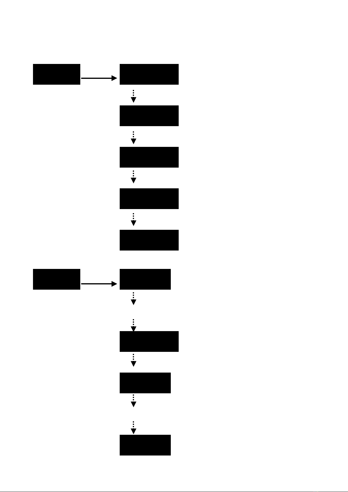
2.2. MENU STRUCTURE
STAT R.000
G.000
N b.000
W.000
ST.00
AUTO AT.01
AT.10
PR.01
PR.10
6
[…]
[…]
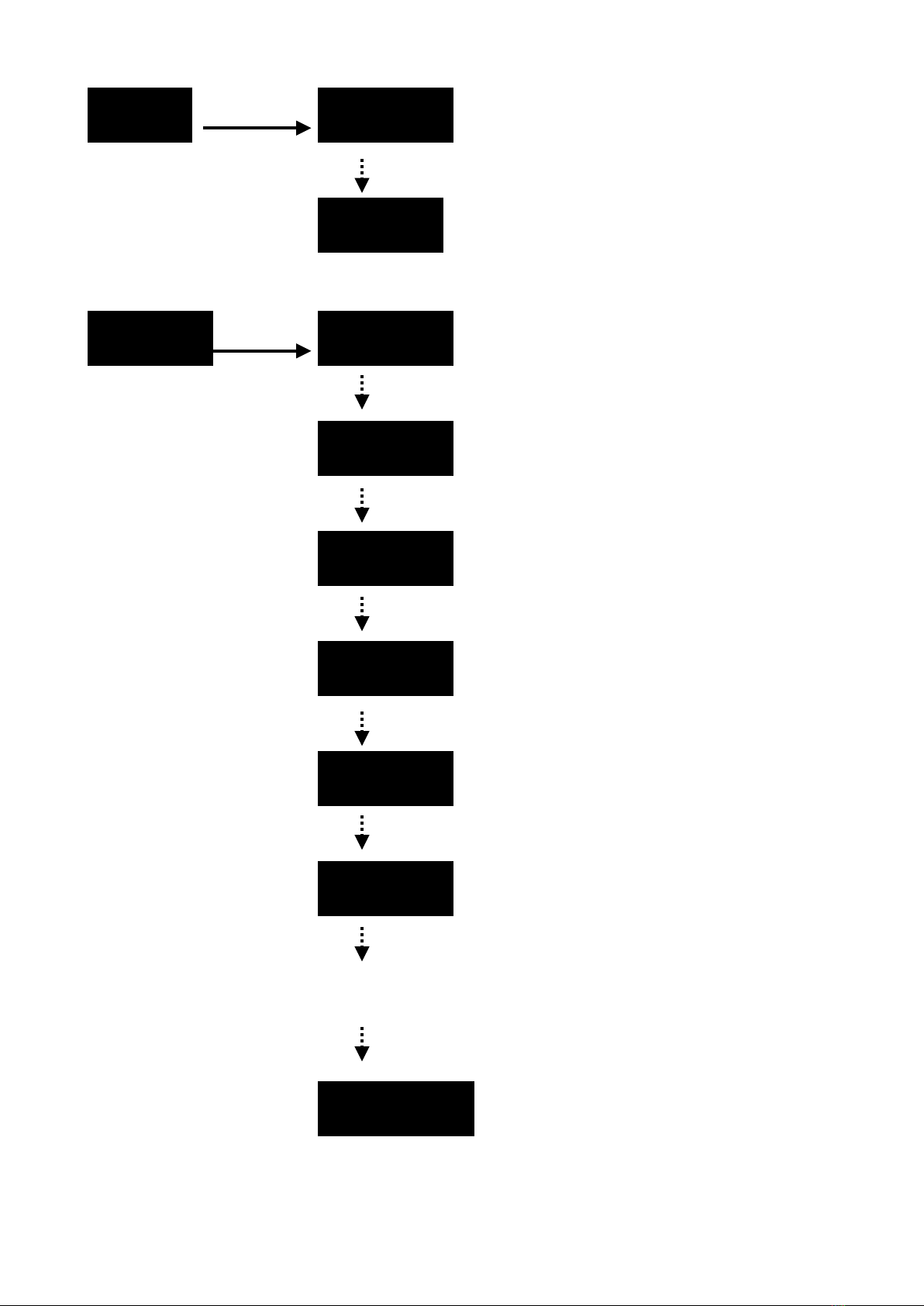
RUN dMX.
SLAV
AddR d.001
d.002
d.003
d.004
d.005
d.006
d.512
7
[…]
PERS STAG.
HSV.
COMP.
COM2.
ARC.1
AR1.d
AR1.S
ARC.2
AR2.d
AR2.S
8

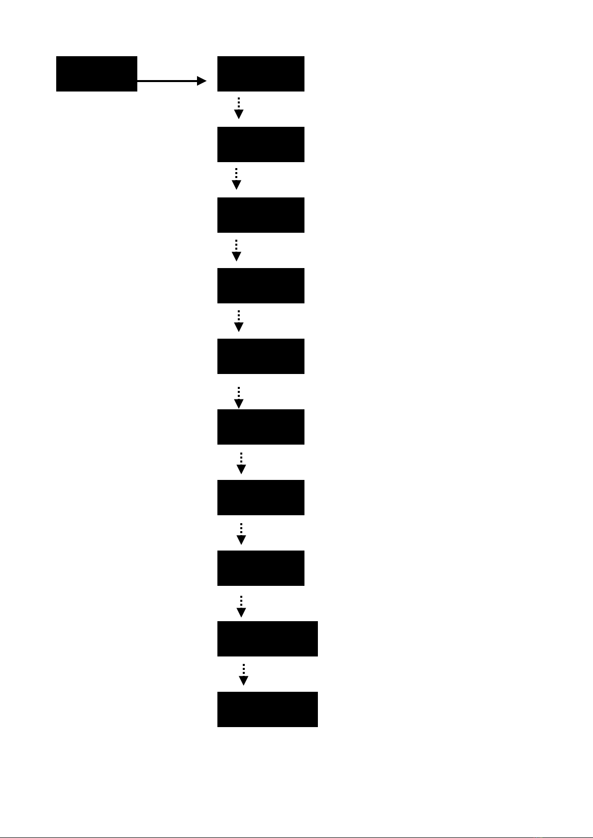
Id Id.01
Id.66
TEMP CURR. 0
EdIT PR.01 SC.01
PR.10 SC.30
9
(0-255)!
(0-255)!
(0-255)!
(0-255)!
(0-20)!
(0-255)!
(0-255)!
[…]
[…]
[…]
R.000
G.000
b.000
W.000
sT.00
T.000
f.000

sET . . . .
. . . .
10
UPLd.
REST.
Id.
RGbW.
dIM.
OFF.
ON.
OFF.
ON.
OFF.
dIM1.
[…]
dIM4.

CAL1 WT.01
WT.11
CAL2 RGbW.
KEY OFF.
ON.
11
R.000
G.000
b.000
W.000
(0-255)!
(0-255)!
(0-255)!
(0-255)!
R.000
G.000
b.000
(25-255)!
(25-255)!
(25-255)!
[…]

2.3 MENU DESCRIPTION
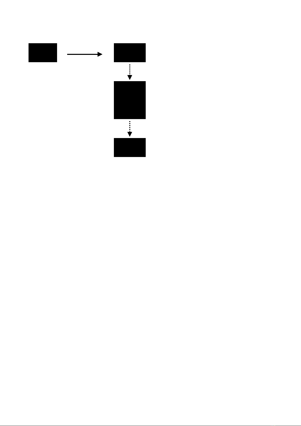
2.3.1 STATIC MODE (STAT)
STAT
To access the static color mode press the MENU button until “STAT”appears on the
display. !
Repeatedly press ENTER button to enter the sub-menu and choose the color and set the
values for the red, green, blue and white LEDs brightness using UP and DOWN buttons
(and eventually activate the strobe effect and set its speed: 0 = OFF, 01-20 = ON, with
increasing frequency). !
Press UP/DOWN buttons to increase (or decrease) the current parameter value, then
press ENTER to switch to the next parameter. !
After selecting the color, you don’t have to exit the submenu. In this way the fixture will
keep these settings as its new default static scene and will continue displaying the last
edited value: even if turned offthis will persist when powered on again after next reboot.!
To exit the static color mode, simply press the MENU button once. This will take you back to the
main menu (“STAT” is displayed), where you can scroll through the various operating modes and
functions.!
12
R.000
G.000
b.000
W.000
sT.00
(0-255)!
(0-255)!
(0-255)!
(0-255)!
(0-20)!
2.3.2 AUTO MODE (AUTO)
AUTO AT.01
AT.10
PR.01
PR.10
To run standard and custom programs press MENU until “AUTO” appears on the display. !
Press ENTER button to enter the sub-menu and choose the desired program by pressing
UP or DOWN button.!
Once you have set the desired program you don’t have to exit the submenu. In this way
the fixture will keep this program as its new default “AUTO” mode and continue displaying
the name of the selected program). Even if the fixture is turned off, it will start the same
program as soon as powered on again.!
To exit the automatic program standalone mode, simply press the MENU button to return
to the main menu. You will see the main menu item "AUTO" displayed again, and you can
scroll through the other operating modes and functions.!
To ensure that many units run the same program smoothly is preferable to set one unit as
a master to run the automatic program in "AUTO" mode and connect other units as
slaves (as explained on page 14). Otherwise, delays may occur between the units after
running the same program for an extended period since each fixture does not have the
same crystal oscillator clock frequency.!
Please note: when DMX channel mode is set on “STAG”, channel 8 can be used to select
one of these programs (AT.01-AT.10 and PR.01-PR.10).!
13

2.3.3 DMX AND SLAVE (RUN)
RUN dMX.
SLAV.
The “RUN“menu allows the user to choose if the light source is going to listen to
incoming DMX signal or operate as a slave unit when in external control mode. !
Press ENTER button and choose the desired mode by pressing UP or DOWN button:
•“dMX“represents standard DMX512 mode. The light source receives a standard
DMX512 signal from a DMX source (or run as standalone when selecting “AUTO“or
“STAT“modes, eventually sending the same color values to all the connected slave
units as Master);!
•“SLAV“represents the Slave mode: the unit will recognise only the signal received from
the Master unit (any standard DMX signal will be passed over). !
To select your desired operating mode, press the MENU button and return to the main
menu. The main menu item "RUN" will be displayed again, and you can scroll through the
other operating modes and functions.!
When using different models of ArchiLED simultaneously, with varying LED configurations
(such as RGB, RGBW, RGBAL) in the same chain, the Master unit must have the most
channels. Additionally, the Master unit must be programmed correctly in one of the
"STAT" or "AUTO" modes by editing one of the PR.01-PR.10 programs to use only the
common channels available on all the different models (usually RGB only).!
In this way the signal will correctly be recognised by all the units and they will work
seamlessly together despite the differences between them.!
By doing so, the signal will be correctly recognised by all units, and they will work
seamlessly synchronised together despite the differences between them.!
14
2.3.4 DMX ADDRESS (AddR)
AddR d.001
To set the DMX starting address for the current unit press MENU until “AddR" appears;
then press ENTER to set the desired address choosing the value by pressing UP or
DOWN button.!
While receiving a standard DMX512 signal the point on the right after the fourth digit will
flash on the lower corner of the display. !
If it does not flash, please check if the console (or any other DMX512 compliant signal
source) is properly connected and transmitting.!
Press MENU button to return to the main menu.
2.3.5 DMX512 CHANNEL MODE (PERS)
PERS STAG.
AR2.S
AR2.d
ARC.2
AR1.S
AR1.d
ARC.1
COM2.
COMP.
HSV.
15
(001-512)!
To set the DMX channel mode press MENU until “PERS” appears.!
"
Press ENTER button and choose the desired mode by pressing UP or DOWN button. !
For specific channel modes description please refer to “Channel Table” (see pages
21-26).!
!
Press MENU button to return to the main menu.!
2.3.6 ID ADDRESS CODE (ID)
Id Id.01
In “STAG“DMX channel mode, series of fixtures with the same DMX address (up to 66
units) can be indexed with a different ID and independently controlled to achieve various
brushing effects, despite having the same channel assignment and starting DMX address.!
To accomplish this utilise the 11th DMX channel to selectively send the other DMX
channel values only to fixtures that share the same selected ID.
To set a different ID for each fixture press MENU until “Id” appears.!
"
Press ENTER button and choose the desired ID by pressing UP or DOWN button. !
Press MENU button to return to the main menu.!
Please note: the ID function must be enabled in native setting menu (“SET”) to work as
described (see page 18).
2.3.7 WORKING TEMPERATURE (TEMP)!
TEMP CURR. 0
To see the current Celsius temperature press MENU until “TEMP” appears; then press
ENTER to access “CURR” menu item.The current working temperature detected inside
the light source will be displayed. !
Please note: the showed temperature may not be so much accurate due to the hardware
material inconsistencies and the mounting position of the thermistor (values between
different units may be different).
16
(01-66)!

2.3.8 SCENE EDITING (EDIT)!
EdIT PR.01 SC.01
PR.10 SC.30
To edit the scene values of a custom program enter the scene editing mode by pressing
MENU until “EdIT” appears and then press ENTER to access the sub-menu. !
Choose the program (PR.01-PR.10) to edit by pressing UP or DOWN button, select it by
pressing ENTER. Select the scene (SC.01-SC.30) of the currently selected program you
want to edit by using UP or DOWN buttons and then press ENTER to scroll through the
scene parameters and change them with UP or DOWN buttons.!
The color component parameters and strobe effect setting is the same of static color
mode (menu “STAT”, see pag. 12).!
“T.000” value represents the overall scene duration, while the “F.000” value is the fade
time between consecutive scenes.!
You can transfer program data between various units by sending the data from a master
unit, which programs are copied to one or more other units that are connected as slave.!
The copied values are all the scenes of the custom programs PR.01-PR.10 which will be
overwritten on all the slave units.
17
R.000
G.000
b.000
W.000
ST.00
T.000
F.000
(0-255)!
(0-255)!
(0-255)!
(0-255)!
(0-20)!
(0-255)!
(0-255)!
Table of contents


