ProLights GAMMAPIX OUTDOORS GAMMAX48T1X2WF User manual

USER MANUAL
English version
GAMMAPIX OUTDOORS
Outdoor LED wall module, SMD1921 WF,
p.4,8mm, 3500nit
REV.01-07/23

Thank you for choosing PROLIGHTS
Please note that every PROLIGHTS product has been designed in Italy to meet quality and performance requirements
for professionals and designed and manufactured for the use and application as shown in this document.
Any other use, if not expressly indicated, could compromise the good condition/operation of the product and/or be
a source of danger.
This product is meant for professional use. Therefore, commercial use of this equipment is subject to the respectively
applicable national accident prevention rules and regulations.
Features, specications and appearance are subject to change without notice. Music & Lights S.r.l. and all afliated
companies disclaim liability for any injury, damage, direct or indirect loss, consequential or economic loss or any other
loss occasioned by the use of, inability to use or reliance on the information contained in this document.
Product user manual can be downloaded from the website www.prolights.it , or can be inquired to the ofcial
PROLIGHTS distributors of your territory (https://www.prolights.it/sales_network.html).
Scanning the below QR Code, you will access the download area of the product page, where you can nd a broad
set of always updated technical documentation: specications, user manual, technical drawings, photometrics,
personalities, xture rmware updates.
The PROLIGHTS Logo, PROLIGHTS names and all other trademark in this document pertaining to PROLIGHTS services
or PROLIGHTS product are trademarks OWNED or licensed by Music & Lights S.r.l., its afliates, and subsidiaries.
PROLIGHTS is a registered trademark by Music & Lights S.r.l. All right reserved. Music & Lights – Via A. Olivetti, snc -
04026 - Minturno (LT) ITALY.
Visit the download area
of the product page

PROLIGHTS - GAMMAPIX 29B1X1BF 01
INDEX
SAFETY INFORMATION 02
1 - OPTIONAL ACCESSORIES 4
2 - TECHNICAL DRAWING 4
3 - PRODUCT OVERVIEW 5
4 - INSTALLATION 6
GROUND BAR STACKING SYSTEM................................................................................. 6
FLY BAR HANGING SYSTEM.......................................................................................... 11
5 - CONNECTION TO THE MAINS SUPPLY 15
6 - START UP 15
CONNECT AND DISCONNECT POWER FROM THE PRODUCT.................................. 15
7 - DATA CONNECTION 16
DATA CABLING .............................................................................................................. 16
MAIN AND BACKUP DATA LINE.................................................................................... 16
8 - LED DISPLAY CONTROL SETTING 18
SYSTEM CONFIGURATION............................................................................................ 18
RESOLUTION MANAGEMENT ...................................................................................... 19
LED SCREEN CONFIGURATION WITH NOVALCT ........................................................ 20
APPLICATION EXAMPLE................................................................................................ 22
9 - MAINTENANCE 25
MAINTENANCE AND CLEANING THE PRODUCT........................................................ 25
MAINTENANCE ON INDOOR PRODUCT ..................................................................... 25
MAINTENANCE ON OUTDOOR PRODUCT ................................................................. 26
CORRECT STARTUP/SHUTDOWN SEQUENCE............................................................. 26
TRANSPORTATION AND STORAGE.............................................................................. 26
GENERAL INDICATIONS FOR USE................................................................................ 27
TROUBLESHOOTING..................................................................................................... 28

PROLIGHTS - GAMMAPIX 29B1X1BF02
SAFETY INFORMATION
WARNING!
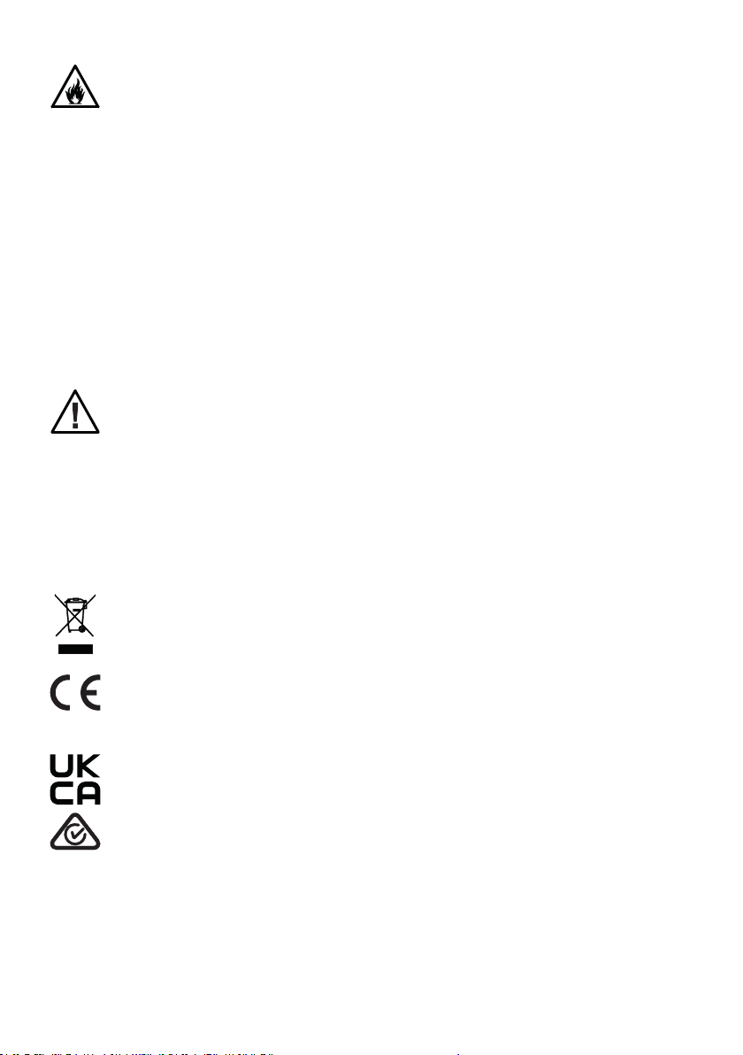
• See https://www.prolights.it/product/GAMMAX48T1X1WF#download for installation
instructions.
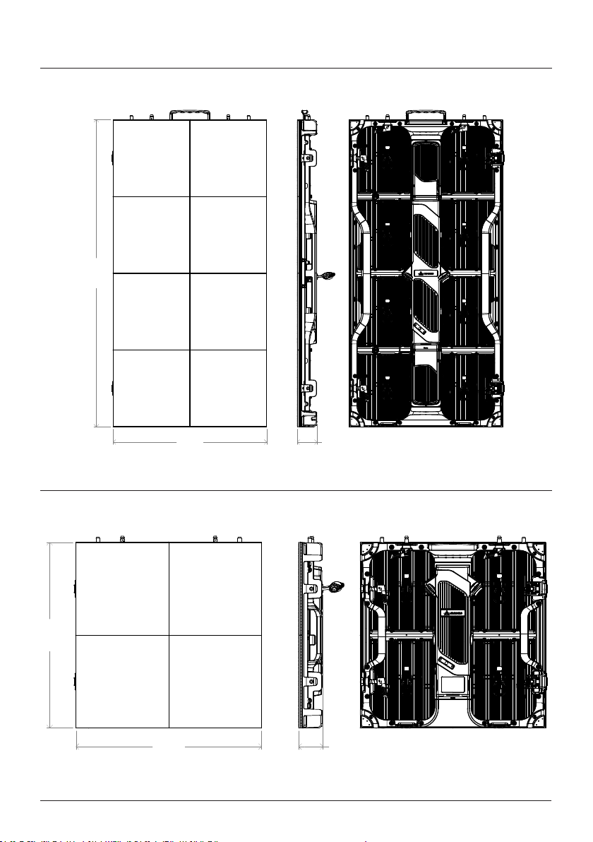
• See https://www.prolights.it/product/GAMMAX48T1X2WF#download for installation
instructions.
• Please read carefully the instruction reported in this section before installing, powering,
operating or servicing the product and observe the indications also for its future handling.
This unit is not for household and residential use, only professional applications.
Connection to mains supply
• The Connection to the mains supply must be carried out by a qualied electrical
installer.
• Use only AC supplies 100-240V 50-60 Hz, the xture must be electrically connected
to ground (earth).
• Select the cable cross section in according with the maximum current draw of the
product and the possible number of products connected at the same power line.
• The AC mains power distribution circuit must be equipped with magnetic+residual
current circuit breaker protection.
• Do not connect it to a dimmer system; doing so may damage the product.
Protection and Warning against electrical shock
• Do not remove any cover from the product, always disconnect the product from AC
power before servicing.
• Ensure that the xture is electrically connected to ground (earth). And use only a
source of AC power that complies with local building and electrical codes and has
both overload and ground-fault (earth-fault) protection.
• Before using the xture, check that all power distribution equipment and cables are
in perfect condition and rated for the current requirements of all connected devices.
• Isolate the xture from power immediately if the power plug or any seal, cover, ca-
ble, or other components are damaged, defective, deformed or showing signs of
overheating.
• Do not reapply power until repairs have been completed.
• Refer any service operation not described in this manual to PROLIGHTS Service team
or an authorized PROLIGHTS service center.
Installation
• Make sure that all visible parts of the product are in good visible condition before its
use or installation.
• Make sure the point of anchorage is stable before positioning the projector.
• When suspending the xture above ground level, secure it against failure of primary
attachments by attaching a safety cable that is approved as a safety attachment for
the weight of the xture to the attachment point on the main frame of the product. ln
case the safety cable, enter in action, it needs to be replaced with a new one.
• Install the product only in well ventilated places.
• For non temporary installations, ensure that the xture is securely fastened to a load-
bearing surface with suitable corrosionresistant hardware.
• For a temporary installation with clamps, ensure that the quarter-turn fastener and/or
screws are turned fully, and secured with a suitable safety cable.

PROLIGHTS - GAMMAPIX 29B1X1BF 03
Protection from burns and re
• The exterior of the xture becomes hot during use. Avoid contact by persons and
materials.
• Ensure that there is free and unobstructed airow around the xture.
• Keep ammable materials well away from the xture.
• Do not expose the front glass to sunlight or any other strong light source from any an-
gle. Lenses can focus the sun’s rays inside the xture, creating a potential re hazard.
• Do not attempt to bypass thermostatic switches or fuses.
IP65
Outdoor (temporary) use
• This product is rated with an IP (Ingress protection) for temporary outdoor use when
used and serviced according to the instruction contained in this document.
• Never use the xture in places subject to vibrations or bumps.
• Make certain that no inammable liquids, water or metal objects enter the xture.
• Excessive dust, smoke uid, and particle build up degrades performance, causes
overheating and will damage the xture.
• Damages caused by inadequate cleaning or maintenance are not covered by the
product warranty.
Maintenance
• Warning! Disconnect the xture from AC mains power and allow to cool for at least
10 minutes before handling.
• Only technicians who are authorized by PROLIGHTS or Authorised service partners
are permitted to open the xture.
• Users may carry out external cleaning, following the warnings and instructions pro-
vided, but any service operation not described in this manual must be referred to a
qualied service technician.
• Important! Excessive dust, smoke uid, and particle build up degrades performance,
causes overheating and will damage the xture. Damages caused by inadequate
cleaning or maintenance is not covered by the product warranty.
Disposal
• This product is supplied in compliance with European Directive 2012/19/EU – Waste
Electrical and Electronic Equipment (WEEE). To preserve the environment please dis-
pose/ recycle this product at the end of its life according to the local regulation.
The products to which this manual refers comply with:
• 2014/35/EU - Safety of electrical equipment supplied at low voltage (LVD).
• 2014/30/EU - Electromagnetic Compatibility (EMC).
• 2011/65/EU - Restriction of the use of certain hazardous substances (RoHS).
Other approvals

PROLIGHTS - GAMMAPIX 29B1X1BF4
1 - OPTIONAL ACCESSORIES
• GXFCM100481X1 Flightcase 10 in1 for GAMMAX48T1X1WF
• GXFCM50481X2 Flightcase 5 in1 for GAMMAX48T1X2WF
• GXHGB01 Fly bar / ground bar per sistemi GAMMAX29B e GAMMAX48T, 1 colonna
• GXHGB02 Fly bar / ground bar per sistemi GAMMAX29B e GAMMAX48T, 2 colonne
• DXBS21 Supporto posteriore 2in1 per moduli DELTAX e GAMMAX series per montaggio a terra
• DXBS31 Supporto posteriore 3in1 per moduli DELTAX e GAMMAX series per montaggio a terra
• DXBS41 Supporto posteriore 4in1 per moduli DELTAX e GAMMAX series per montaggio a terra
• DXBSC Piastra posteriore per moduli DELTAX e GAMMAX series per il montaggio a terra
• DXXJ Giunto metallico per unire 4 cabinet serie DELTAX e GAMMAX, foro M10 per gancio
• GXCJ Piastra curvabile per cabinets ledwall GAMMAX series
• OXFCIS100 Flightcase per strutture rigging/ground-stack OMEGAX-DELTAX series, 100cm
• OXFCIS200 Flightcase per strutture rigging/ground-stack OMEGAX-DELTAX series, 200cm
• OXFCSP Flightcase per parti di ricambio per moduli LED-display OMEGAX-DELTAX series
• OXACL01 Cavo di alimentazione per led display series, L.140 cm
• OXACL10 Cavo di alimentazione per led display series L.10 m
• SXDCL01 Cavo dati per SIGMAX LED display series assemb. con RJ45, L 140 cm
• SXDCL10 Cavo dati per SIGMAX LED display series assemb. con RJ45, L 10 m

PROLIGHTS - GAMMAPIX 29B1X1BF 5
500 mm
[19.7 in]
64 mm
[2.5 in]
1000 mm
[39.4 in]
Weight: 11,4 kg - 25,13 lbs
2 - TECHNICAL DRAWING
500 mm
[19.7 in]
500 mm
[19.7 in]
66 mm
[2.6 in]
Fig. 02
Weight: 6,4 kg - 14,11 lbs
GAMMAX48T1X1WF
GAMMAX48T1X2WF
Fig. 01

PROLIGHTS - GAMMAPIX 29B1X1BF6
3 - PRODUCT OVERVIEW
1. MODULE: single LED display module that makes up the cabinet with magnetic attachment
2. SIDE LOCK MECHANICS: Side Panel locking and unlocking mechanism.
3. UPPER LOCK MECHANICS: Upper Panel locking and unlocking mechanism.
4. POWER IN CONNECTOR: for connection to the Mains 100-240V~/50-60Hz.
5. POWER OUT CONNECTOR: power output for connection of multiple units in series.
6. POSITIONING PIN: allows to center and hook cabinet easier.
7. CORNER PROTECTION
8. ANGLE MECHANICS: allow both concave and convex precise installation of +10° / -10°.
9. MOUNTING HOLE: to be used to x the cabinets together using a metal plate.
10. LOCKING TAB: to hook cabinet to underside.
11. SIGNAL CONNECTORS: Ethernet connectors for sending and receiving Data Information from the
controller.
12. CABLE LOCK: block to secure DATA and Power cables
13. CABINET HANDLE: handy handles for easy assembly.
Fig 03
1
26
4
11
10 13
38
9
5
11 12
7

PROLIGHTS - GAMMAPIX 29B1X1BF 7
4 - INSTALLATION
GROUND BAR STACKING SYSTEM
Fig 04
Allign the ground beam GXHGB01 / GXHGB02, then adjust the height of the ground foot to keep
the ground beam horizontally.
Screw the two down bolts of the DXBS21 to the ground beam GXHGB01 / GXHGB02 throught the
back frame DXBSC.

PROLIGHTS - GAMMAPIX 29B1X1BF8
Fig 05
Install the cabinet.
Screw the two top bolts of the DXBS21 to the cabinet.

PROLIGHTS - GAMMAPIX 29B1X1BF 9
Fig 06
To mount the cabinets horizontally, use the specic side locks by push and turning the locking lever.
Complete the line for then assemble the next line.

PROLIGHTS - GAMMAPIX 29B1X1BF10
Fig 07
To mount the cabinets vertically, match the pins of the cabinet below with the holes of the cabinet
you are mounting.
To lock the cabinets vertically, use the upward lock by push and turning the locking lever.

PROLIGHTS - GAMMAPIX 29B1X1BF 11
Fig 08
Install the DXBSC back plate between cabinets in case of complex installations.
Finally, repeat all the previous steps to complete the Video Wall.

PROLIGHTS - GAMMAPIX 29B1X1BF12
FLY BAR HANGING SYSTEM
Fig 09
Fasten the y GXHGB01 / GXHGB02 y bars at the structure.
Install the cabinet on the ybars by matching the pins to the holes in the bars.

PROLIGHTS - GAMMAPIX 29B1X1BF 13
Fig 10
To lock the cabinets vertically, use the upward lock by push and turning the locking lever.
Pay attention that the cabinets are well aligned and make sure there are no steps between panels
horizontally and on the front of the panels.

PROLIGHTS - GAMMAPIX 29B1X1BF14
Fig 11
Use the specic side locks by push and turning the locking lever, to hook the cabinets horizontally
Install the DXXJ back plate between cabinets and Flybar.

PROLIGHTS - GAMMAPIX 29B1X1BF 15
Fig 12
Finally, fasten other cabinets sequentially from top to bottom and from middle to both sides (the
number of cabinets in vertical direction shall not be more than 10 cabinets, while i in the horizontal
direction is not restricted)

PROLIGHTS - GAMMAPIX 29B1X1BF16
5 - CONNECTION TO THE MAINS SUPPLY
Each cabinet has an IN and OUT power connection (powercon true or powercon). It’s possible to con-
nect in chain many cabinets. To design the power cabling, it’s necessary to know the max power con-
sumption for each panel. It’s possible to see this info in the specications of the product
Examples:
Fig. 13
WARNING: For protection from electric shock, the panel must be earthed!
The product is equipped with auto-switching power supply that automatically adjusts to any 50-60Hz
AC power source from 110-230 Volts.
If you need to install a power plug on the power cable to allow connection to power outlets, install a
grounding-type (earthed) plug, following the plug manufacturer’s instructions. If you have any doubts
about proper installation, consult a qualied electrician.
The maximum power consumption of single panel is 120W.
MAIN
POWER
LINE
IN OUT
Core (EU) Core (US) Connection Plug terminal marking
Brown Black Live L
Blue White Neutral N
Yellow+green Green Earth
NOTE: it’s suggested to use a class D switch.
6 - START UP
CONNECT AND DISCONNECT POWER FROM THE PRODUCT
To apply and disconnect power to the product:
• Check that the product is installed and secured as indicated in the Safety Informations, and that
personal safety will not be put at risk when the xture lights up.
• Connect the power connector into the Mains input socket (100-240 VAC-50/60 Hz).
• The product is then ready for its operations and can be controlled through the available input sig-
nals on board.
• To disconnect power from the product, disconnect the Mains from the socket.

PROLIGHTS - GAMMAPIX 29B1X1BF 17
7 - DATA CONNECTION
DATA CABLING
Each cabinet has an IN and OUT data connection (RJ45). Each data output of a Novastar processor,
can manage a max of 650.000 pixels. To design the cabling of data, it’s necessary to know the
resolution of each cabinet.
Examples:
Fig. 14
NOTE: it’s suggested to distribute the signal as evenly as possible between the various signal lines.
NOTE: it’s necessary to complete a row or a column with a data chain. It’s not possible to connect half
of a row or a column on a data chain.
MAIN AND BACKUP DATA LINE
For all Prolights led screen cabinet it’s possible to install a MAIN data line and a BACKUP data line. This
allows to see image on led screen in case of MAIN failure. MAIN and BACKUP need to be assigned
from the PC software to the outputs of the processor.
MAIN data cable comes from the output of the processor to the last cabinet of the chain.
BACKUP data cable come from the output of the last cabinet of the chain to the output of the proces-
sor.
MAIN
DATA
LINE
IN OUT
Product Cabinet Total Pixels Max number of cabinets for a data line
SIGMA X26 series (192x192 pixels)
36.864 17
GAMMA X29 series (168x168 pixels)
28.224 23
SIGMA X39 series X1 (128x128 pixels)
16.384 39
SIGMA X39 series X2 (128x256 pixels)
32.768 19
GAMMA X48 series X1 (104x104 pixels)
10.816 60
GAMMA X48 series X2 (104x208 pixels)
21.632 30
KAPPA X26 series (192x192 pixels)
36.864 17

PROLIGHTS - GAMMAPIX 29B1X1BF18
Fig. 15
IN OUT
OUT
IN
First cabinet
of the chain
Last cabinet
of the chain
DATA BACKUP
DATA MAIN
NOTE: it’s always suggested to use different processor for MAIN line and BACKUP line
Table of contents
Other ProLights Monitor manuals