PRORUN PRM48V38 User manual
Unpacking and Setup
WEAR HEAVY GLOVES.
109 6
8
7
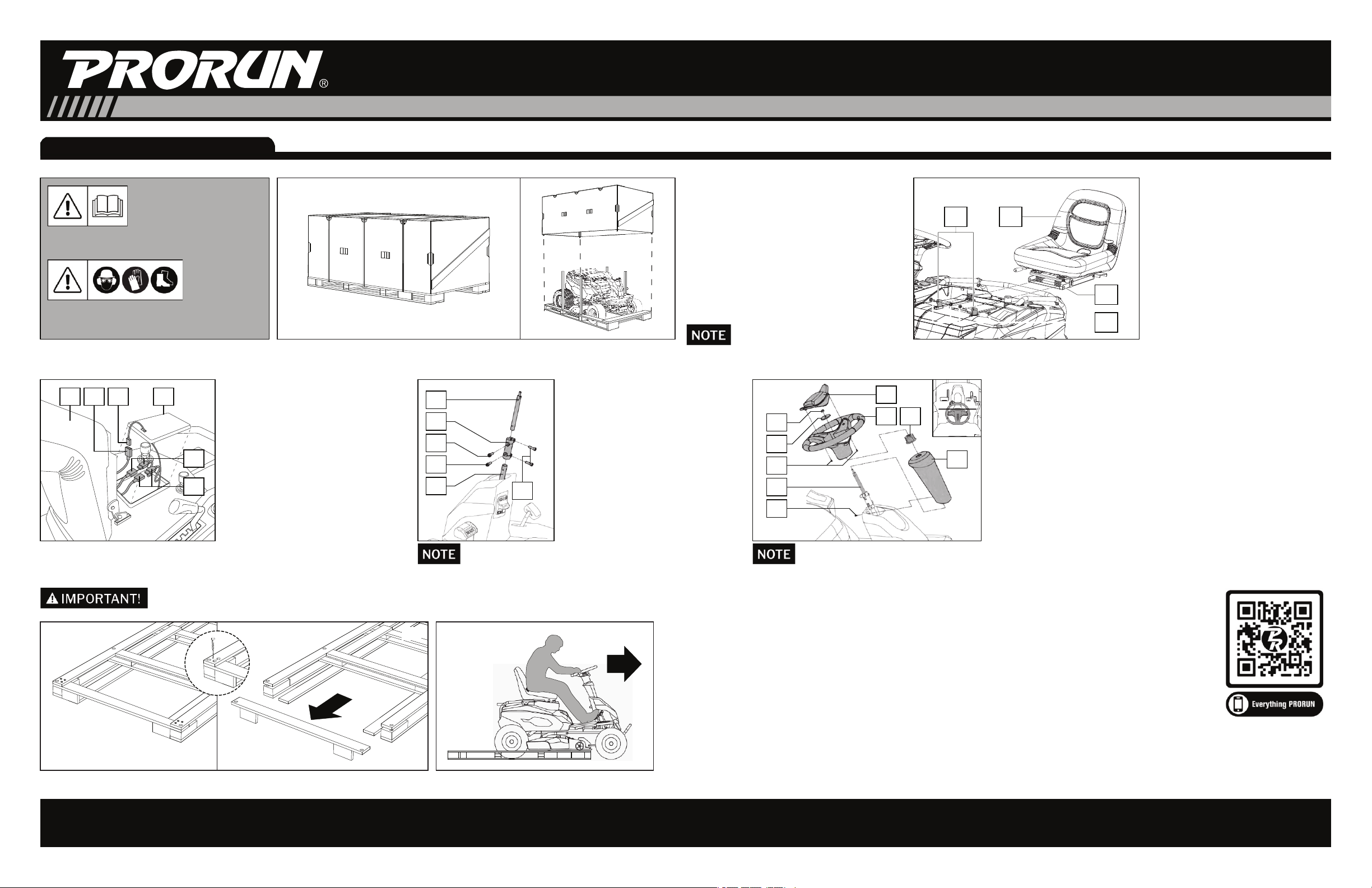
53. CONNECT BATTERY AND
OPERATOR PRESENCE
SWITCH
A. Lift the Seat (5) and remove the
Battery Compartment Lid (6)
B. Connect the RED Positive Wire
Connectors (7) and the BLACK
Negative Wire Connectors (8),
C. Connect the Wire Harness (9) to
the Operator Presence Switch
(10) under the seat.
D. Replace Battery Compartment
Lid (6)
13
11
14
12
15
16
4. MOUNT THE STEERING
COLUMN
A. Mount the Coupler (11) onto the
mower's Steering Shaft (12)
using screw M8 x 20 (13).
B. Insert the Steering Column (14)
into the Coupler (11) and fasten
with screw M8 x 20 (15).
C. Complete assembly by
tightening the screws M8 x 20
(16).
19
17
18
21
24
20
22
23
25
Figure A
5. MOUNTING THE STEERING COLUMN COVER AND STEERING WHEEL
A. Remove the Column Cover Screw M6 X 25 (17) from the bucket nut
mounted onto the Column Cover (18).
B. Slide the Column Cover (18) over the Steering Column assembly (19).
Reinsert and tighten Column Cover Screw M6 X 25 (17).
C. Insert the Splined Hub (20) onto the Steering Column assembly (19).
Mount the Steering Wheel (21), Spacer (22), and secure assembly with
Nut M8 (23).
D. Insert Steering Wheel Cover (24) into the Steering Wheel (6) and secure
with two Screws (25) (Screws are typically found installed in the
Steering Wheel Cover).
BE SURE TO ALIGN DIRECTION OF STEERING WHEEL AS SHOWN IN FIGURE A.
NEED HELP? Call PRORUN Customer Service at 704-698-8036 (toll-free), or email [email protected].
POWER and RELIABILITY
2. MOUNT THE SEAT
A. Remove the two nuts and bolt (1)
from mower's mounting brackets
(2).
B. Place the Seat (3) on top of springs
and align the holes on the seat's
mounting bracket (4) with the holes
in mower's mounting brackets (2).
C. Reinsert the two nuts and bolt (1)
and tighten. Test that Seat rotates
upwards towards the steering
wheel.
1. OPENING THE PACKAGING
The machine is shipped partially dismantled
and packaged in a metal crate to protect it
during transport. The packaged machine will
appear as in Fig 1A.
A. Remove all shrink wrap and cut the two
plastic straps that surround the package.
B. Lift off the corrugated exterior cover
assembly and discard the four wooden
support posts. (Fig 1B)
WARNING: When working with the product,
wear the required personal safety equipment.
IMPORTANT: Read the Operator’s manual
thoroughly, and follow safe operating practices.
1A 1B
AFTER INSTALLING THE STEERING WHEEL AND SEAT, INCREASE THE TRACTOR'S CUTTING DECK HEIGHT TO ITS MAXIMUM LEVEL.
6. DRIVE RIDING MOWER OFF THE PALLET
A. After installing the steering wheel and seat,
increase the tractor's cutting deck height to its
maximum level.
B. Remove the six bolts near the front of riding
mower's pallet (Fig 6A) and remove the wooden
cross plank from the base pallet. (Fig 6B).
C. Follow the instructions in section CONTROLS AND
STARTUP and carefully drive the Riding Mower
forward off the wooden base platform. (Fig 6C)
6C
6A 6B
Get the most out of your PRORUN equipment,
scan the QR code for helpful instructional videos,
quick-start guides, manuals, parts lists, and more.
48V Riding Lawnmower
Model: PRM48V38
3
2
1
4
THE SCREWS FOR THIS ASSEMBLY ARE TYPICALLY
FOUND INSTALLED IN THE COUPLE.
Quick Start Guide / Unpacking and Setup

NEED HELP? Call PRORUN Customer Service at 704-698-8036 (toll-free), or email [email protected]. And to get the most
out of your PRORUN equipment, scan the QR code for helpful instructional videos, quick-start guides, manuals, parts lists, and more.
POWER and RELIABILITY
48V Riding Lawnmower Model: PRM48V38
4. MOUNT THE
STEERING
COLUMN
5. MOUNT THE STEERING
COLUMN & STEERING WHEEL
3. CONNECT BATTERY &
OPERATOR PRESENCE SWITCH
2. MOUNT THE SEAT
Setup - Refer to Operator’s Manual
WARNING: When working with the product,
wear the required personal safety equipment.
IMPORTANT: Read the Operator’s manual
thoroughly, and follow safe operating practices.
1A 1B
Unpacking
1. OPENING THE PACKAGING
The machine is shipped partially dismantled and packaged in a metal crate to protect it during transport. See Figure 1A
A. Remove all shrink wrap and cut the two plastic straps that surround the package.
B. Lift off the corrugated exterior cover assembly and discard the four wooden support posts. (Fig 1B)
6C
6A 6B
Drive off
6. DRIVE RIDING MOWER OFF THE PALLET
A. After installing the steering wheel and seat, increase the tractor's cutting deck height to its maximum level.
B. Remove the six bolts near the front of riding mower's pallet (Fig 6A) and remove the wooden cross plank from the base pallet. (Fig 6B).
C. Follow the instructions in section CONTROLS AND STARTUP & carefully drive the Riding Mower forward off the wooden base platform. (Fig 6C)
Scan QR code
for helpful
instructional videos.
Other PRORUN Lawn Mower manuals

Popular Lawn Mower manuals by other brands

Dolmar
Dolmar PM5600S3R Original instruction manual

Makita
Makita ELM3320 instruction manual

Poulan Pro
Poulan Pro 402495 Operator's manual

Poulan Pro
Poulan Pro 418771 Operator's manual

Simplicity
Simplicity Snapper 2690716 Operator's manual

Country Clipper
Country Clipper JAZee One SR100 Safety instructions & operator's manual


Cub Cadet
Cub Cadet 18M Operator's manual

Makita
Makita DLM480 instruction manual

Ransomes
Ransomes Mastiff 91 Operation and maintenance guide

Craftsman
Craftsman 247.772460 Operator's manual

Grizzly
Grizzly ARM 4041 Lion Set Translation of the original instructions for use

Troy-Bilt
Troy-Bilt 11A-436N063 parts manual