ProSound L84AN User manual

Professional Speaker System
USER'S MANUAL
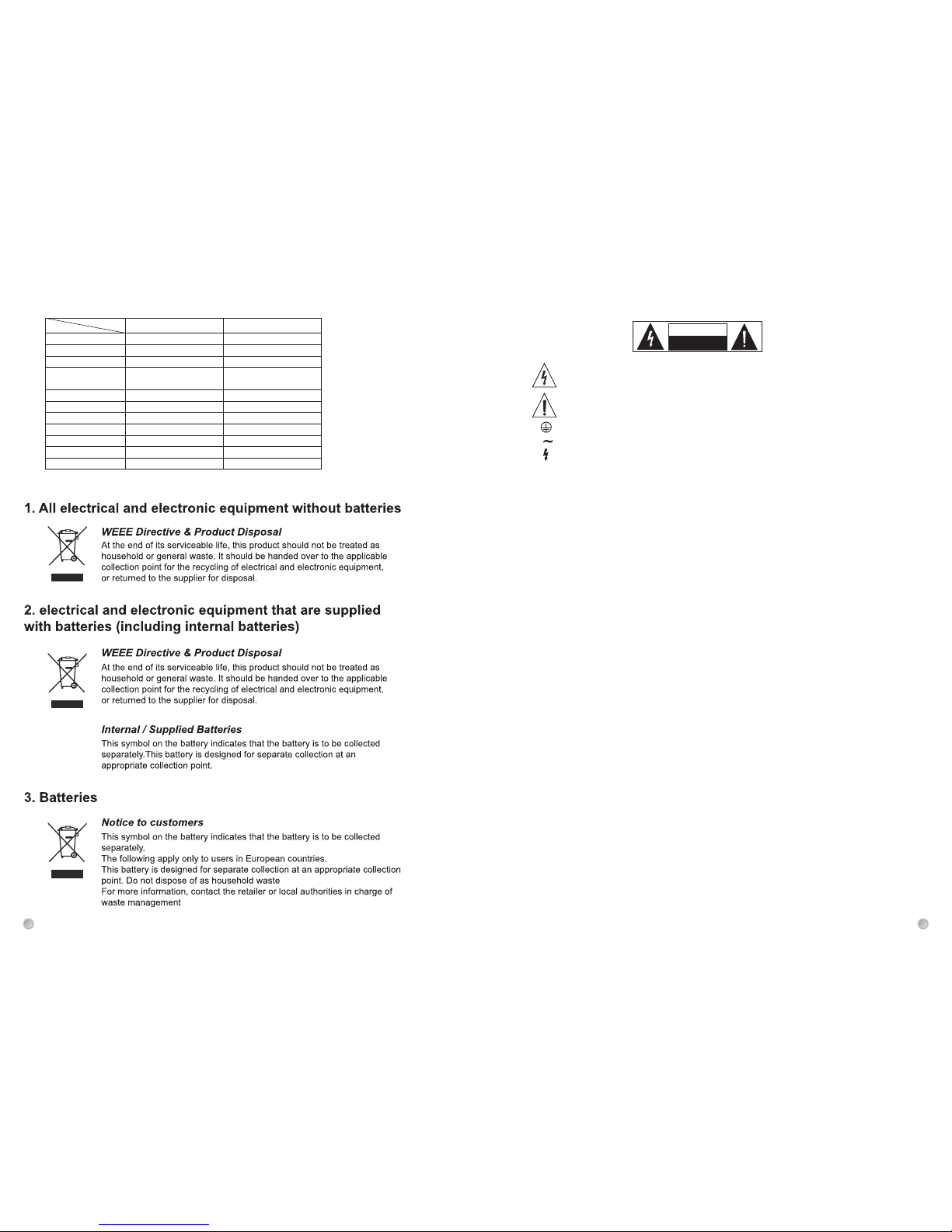
The symbol is used to indicate that some hazardous live terminals are involved within this apparatus, even
under the normal operating conditions, which may be sufficient to constitute the risk of electric shock or
death.
The symbol is used in the service documentation to indicate that specific component shall be replaced
only by the component specified in that documentation for safety reasons.
Protective grounding terminal
Alternating current/voltage
Hazardous live terminal
ON: Denotes the apparatus is turned on
OFF: Denotes the apparatus is turned off.
WARNING: Describes precautions that should be observed to prevent the danger of injury or death to the operator.
CAUTION: Describes precautions that should be observed to prevent danger of the apparatus.
IMPORTANT SAFETY INSTRUCTIONS
·Read these instructions.
·Keep these instructions.
·Heed all warning.
·Follow all instructions.
Water & Moisture·
The apparatus should be protected from moisture and
rain, can not used near water, for example: near bath-
tub, kitchen sink or a swimming pool, etc.
·Heat
The apparatus should be located away from the heat
source such as radiators, stoves or other appliances
that produce heat.
·Ventilation
Do not block areas of ventilation opening. Failure to
do could result in fire. Always install accordance with
the manufacturer's instructions.
·Object and Liquid Entry
Objects do not fall into and liquids are not spilled into
the inside of the apparatus for safety.
·Power Cord and Plug
Protect the power cord from being walked on or pinched
particularly at plugs, convenience receptacles, and the
point where they exit from the apparatus.
Do not defeat the safety purpose of the polarized or
grounding-type plug. A polarized plug has two blades
with one wider than the other. A grounding type plug
has two blades and a third grounding prong. The wide
blade or the third prong is provided for your safety.
If the provided plug does not fit into your outlet, refer to
electrician for replacement.
CAUTION
RISK OF E LECTRIC S HOCK
DO NOT OP EN
IMPORTANT SAFETY SYMBOLS
°
·Power Supply
The apparatus should be connected to the power supply
only of the type as marked on the apparatus or described
in the manual. Failure to do could result in damage to the
product and possibly the user.
Unplug this apparatus during lightning storms or when
unused for long periods of time.
·Fuse
To prevent the risk of fire and damaging the unit, please
use only of the recommended fuse type as described in
the manual. Before replacing the fuse, make sure the unit
turned off and disconnected from the AC outlet.
·Electrical Connection
Improper electrical wiring may invalidate the product war-
ranty.
·Cleaning
Clean only with a dry cloth. Do not use any solvents such
as benzol or alcohol.
·Servicing
Do not implement any servicing other than those means
described in the manual. Refer all servicing to qualified
service personnel only.
·Only use accessories/attachments or parts recommended
by the manufacturer.
·Warning
Please remember the high sound pressure do not only
temporarily damage your sense of hearing, but can also
cause permanent damage. Be careful to select a suitable
volume.
1
2
8
Specifications
Frequency response
Model
45Hz-18KHz45Hz-18KHz
L84AN N08CQ
SPL(1W@1m)
Programme power
Power rating internal
power amp
Impedence(nominal)
Crossover frequency
HF driver type
LF driver type
Connections
Dimensions(HxWxD)
Weight
600W max
8Ω
Speakon/Jack
630×330×410 mm
22 kg
800W max
HF 50W rms
LF 400W rms
8Ω
XLR signal
720×365×495 mm
25 kg
2.5KHz
1-inch compression driver
15-inch powertone driver
2.5KHz
1.35-inch compression driver
12-inch driver
96dB
HF 50W rms
LF 300W rms
1. INTRODUCTION
The professional speaker system is divided active speaker and passive speaker, it consists of seven sizes, each
sizes includes several models, following list will show you the details.
6" 2-way speaker system
·Passive speaker system
12" 2-way speaker system 15" 2-way speaker system
AL Basket AL Basket
8" 2-way speaker system
5. TECHNICAL SPECIFICATIONS
5.1 Passive Speaker System
Specifications
Frequency response
Model
50Hz-18KHz75Hz-20KHz
L56AQ N05CQ
5.2 Active Speaker System
7
2
2
6" 2-way speaker system
·Active speaker system
12" 2-way speaker system 15" 2-way speaker system
AL Basket AL Basket
2. PASSIVE SPEAKER SYSTEM
2.1 Features
·Enclosure adopted a high impact polymer, injection molded shaping. It has high intensity and light weight, set a
handle, easy to carry it. Designed non-symmetrical enclosure outline. It can be used for fold-back speaker.
·Woofer speaker make a high powered pro-speaker. It has wide-range, low distortion, high sensitivity, adopted a
aluminum frame. It has non-mechanical resonance.
·Driver selected a titanium diaphragm, and light mass voice coil, make it high frequency reached 18,000Hz.
·Crossover adopted a high quality polypropylene condenser, flame proof resistor, low less inductance. Precision
design dividing frequency and smooth frequency response.
2.2 Control Element
6", 8", 10", 12", 15" 2-WAY
INPUT OUTPUT
+
+
+
+
INPUT
Binding post/1/4" TRS jack/Speakon INPUT connectors, serve to receive the powered signal coming from an
external power amplifier. If necessary, some of these can be regarded a link output connector.
8" 2-way speaker system
10" 2-way speaker system
AL Basket
10" 2-way speaker system
AL Basket
Steel Basket
Steel Basket Steel Basket
Steel Basket Steel Basket
Steel Basket
SPL(1W@1m)
Programme power
Power handling
Impedence(nominal)
Crossover frequency
HF driver type
LF driver type
Connections
Dimensions(HxWxD)
Weight
93dB 95/118dB
300W max
150W rms
8Ω
1/4 Jack & terminal posts
410×230×280 mm
6 kg
--------
--------
--------
500W max
250W rms
8Ω
Speakon/Jack
530×310×345 mm
14 kg
2.5KHz
1-inch compression driver
10-inch powertone driver
Specifications
Frequency response
Model
45Hz-18KHz45Hz-18KHz
L14AN N07CQ
SPL(1W@1m)
Programme power
Power handling
Impedence(nominal)
Crossover frequency
HF driver type
LF driver type
Connections
Dimensions(HxWxD)
Weight
96dB 97/123dB
600W max
300W rms
8Ω
630×330×410 mm
19 kg
800W max
400W rms
8Ω
Speakon/Jack
720×365×495 mm
22 kg
2.5KHz
1 compression driver
15powertone driver
2.5KHz
1.35-inch compression driver
12-inch driver
Speakon/Jack
Specifications
Frequency response
Model
50Hz-18KHz60Hz-18KHz
N04CQ N06CQ
SPL(1W@1m)
Programme power
Power rating internal
power amp
Impedence(nominal)
Crossover frequency
HF driver type
LF driver type
Connections
Dimensions(HxWxD)
Weight
300W max
50W rms
8Ω
Jack signal in & Link
410×230×280 mm
10 kg
500W max
HF 50W rms
LF 200W rms
8Ω
XLR signal
530×310×345 mm
18.5 kg
2.5KHz
1.35-inch compression driver
10-inch powertone driver
2.5KHz
1-inch HF dome tweeter
8-inch powertone driver
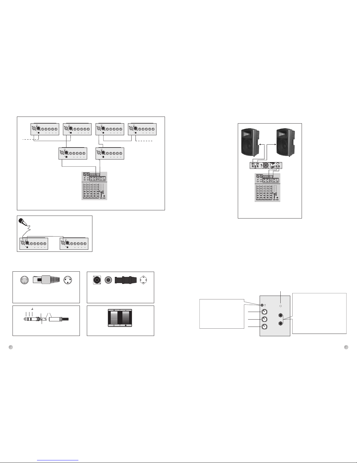
2.3 Connection Examples
3. ACTIVE SPEAKER SYSTEM
3.1 Features
·Enclosure adopted a high impact polymer, injection molded shaping. It has high intensity and light weight, set a
handle, easy to carry it. Designed non-symmetrical enclosure outline. It can be used for fold-back speaker.
·Woofer speaker make a high powered pro-speaker. It has wide-range, low distortion, high sensitivity, adopted a
aluminum frame. It has non-mechanical resonance.
·Driver selected a titanium diaphragm, and light mass voice coil, make it high frequency reached 18,000Hz.
·The new CLIP (Automatic amplitude Clipper system) processor ensures total protection of the transducers and
improvement of the acoustic response.
3.2 Control Element
MIC
LINE
100
GAI N
HILOW
TON E
100
VOL UME
INP UT
AUX O UT
POW ER
6", 8" 2-way
6
4
12
11
LINE/MIC
Switch to select either "MIC"
position if a microphone or a low
level appliance is connected;
the "LINE" position allows
connection of high level signal
sources.
IN link OUT
Input and output sockets, electronically
balanced. The "IN" XLR socket allows
connection of a dynamic microphone
at low impedance or of a pre-amplified
signal such as a mixer line out; the
"OUT" socket is connected in parallel
(link) with the input "IN" allowing
multiple connection of more systems
with the same signal.
Configuration of multiple 2×10" /12" /15"
2-way through the XLR output socket
"OUT" in parallel (link) with the XLR "IN"
socket
PWR
MIC
LINE
CLIP
LIFT
GND
100 0
-15 +15dB
0
-12 +12dB
0
-15 +15dB
-
8
-45 mic
-15 line
-
8
VOL
LOW
MID
HIGH
GAIN
LINE IN
XLR
1. Gnd
2. Hot
3. Cold
XLR
3
2 1
OUT
MIC
PWR
MIC
LINE
CLIP
LIFT
GND
100 0
-15 +15dB
0
-12 +12dB
0
-15 +15dB
-
8
-45 mic
-15 line
-
8
VOL
LOW
MID
HIGH
GAIN
LINE IN
XLR
1. Gnd
2. Hot
3. Cold
XLR
3
2 1
OUT
MIC
10
0
0
10
0
0
5/6
1
PAN
MID
2.5 KHz
HIGH
12 KHz
EFF/
AUX
LOW
80Hz
LR
L
R
MONO
L/MONO R
8 CHANNELS STEREO MIXER
+10
+7
+4
+2
0
-
2
-
4
-
7
-
10
-
20
+48 V
POWER
+48V
2TK TO CTRL ROOM
2TK TO MIX
MAIN MIX
LEVEL
AUX/
SEND
PHONE
L
R
LEVEL
PEAK
- -
- -
- -
- -
- -
- -
- -
- -
- -
- -
EFFECT
REPEAT
DELAY
PAN
EFF/AUX
LEVEL
STEREO
AUX RETURN
AUX SEND
MAIN OUT
TAPE IN
TAPE OUT
LINE
MIC
GAIN
RETURN
15
0
5
10
15
20
25
30
40
50
+dB
-dB
Professio nal Mixer
+15-15
0
+15-15
0
+15-15
0
+15-15
0
-10
+4
-10
+4
LINE
MIC
GAIN
2
7/8
LEVEL
+15-15
0
+15-15
0
+15-15
0
+15-15
0
PEAK
LEVEL
+15-15
0
+15-15
0
+15-15
0
+15-15
0
LEVEL
+15-15
0
+15-15
0
+15-15
0
+15-15
0
L
R
MONO
+15-15
0
+15-15
0
+15-15
0
+15-15
0
CTRLR OUT PHONE
L
R
LINE 7/8LINE 5/6
10
0
8
10
0
8
RL
1 2
10
0
8
RL
10
0
8
RL
10
0
8
RL
PAN
MID
2.5 KHz
HIGH
12 KHz
EFF/
AUX
LOW
80Hz
PAN
MID
2.5 KHz
HIGH
12 KHz
EFF/
AUX
LOW
80Hz
PAN
MID
2.5 KHz
HIGH
12 KHz
EFF/
AUX
LOW
80Hz
10" /12" /15" 2-way
PWR
MIC
LINE
CLIP
LIFT
GND
100 0
-15 +15dB
0
-12 +12dB
0
-15 +15dB
-
8
-45 mic
-15 line
-
8
VOL
LOW
MID
HIGH
GAIN
LINE IN
XLR
1. Gnd
2. Hot
3. Cold
XLR
3
2 1
OUT
MIC
PWR
MIC
LINE
CLIP
LIFT
GND
100 0
-15 +15dB
0
-12 +12dB
0
-15 +15dB
-
8
-45 mic
-15 line
-
8
VOL
LOW
MID
HIGH
GAIN
LINE IN
XLR
1. Gnd
2. Hot
3. Cold
XLR
3
2 1
OUT
MIC
PWR
MIC
LINE
CLIP
LIFT
GND
100 0
-15 +15dB
0
-12 +12dB
0
-15 +15dB
-
8
-45 mic
-15 line
-
8
VOL
LOW
MID
HIGH
GAIN
LINE IN
XLR
1. Gnd
2. Hot
3. Cold
XLR
3
2 1
OUT
MIC
PWR
MIC
LINE
CLIP
LIFT
GND
100 0
-15 +15dB
0
-12 +12dB
0
-15 +15dB
-
8
-45 mic
-15 line
-
8
VOL
LOW
MID
HIGH
GAIN
LINE IN
XLR
1. Gnd
2. Hot
3. Cold
XLR
3
2 1
OUT
MIC
PWR
MIC
LINE
CLIP
LIFT
GND
100 0
-15 +15dB
0
-12 +12dB
0
-15 +15dB
-
8
-45 mic
-15 line
-
8
VOL
LOW
MID
HIGH
GAIN
LINE IN
XLR
1. Gnd
2. Hot
3. Cold
XLR
3
2 1
OUT
MIC
PWR
MIC
LINE
CLIP
LIFT
GND
100 0
-15 +15dB
0
-12 +12dB
0
-15 +15dB
-
8
-45 mic
-15 line
-
8
VOL
LOW
MID
HIGH
GAIN
LINE IN
XLR
1. Gnd
2. Hot
3. Cold
XLR
3
2 1
OUT
MIC
OUT OUT
IN IN
L R
MAIN OUT
Mixer
10" / 12" / 15" 2-way
Connection of 1 microphone and of 2×10"/12"/
15" 2-way in parallel mode.
Do not point the microphone to the loudspeakers
(larsen effect).
4. WIRING
XLR
1
2
31
2
3
1: Shield 2: Hot (+) 3: Cold (-)
1+
1-
2+
2-
SPEAKON
Tip
Ring
Sleeve
+
-
1/4" TRS JACK BINDING POST
3
2
6
10
0
0
10
0
0
5/6
1
PAN
MID
2.5 KHz
HIGH
12 KHz
EFF/
AUX
LOW
80Hz
LR
L
R
MONO
L/MONO R
8 CHANNELS STEREO MIXER
+10
+7
+4
+2
0
-
2
-
4
-
7
-
10
-
20
+48 V
POWER
+48V
2TK TO CTRL ROOM
2TK TO MIX
MAIN MIX
LEVEL
AUX/
SEND
PHONE
L
R
LEVEL
PEAK
- -
- -
- -
- -
- -
- -
- -
- -
- -
- -
EFFECT
REPEAT
DELAY
PAN
EFF/AUX
LEVEL
STEREO
AUX RETURN
AUX SEND
MAIN OUT
TAPE IN
TAPE OUT
LINE
MIC
GAIN
RETURN
15
0
5
10
15
20
25
30
40
50
+dB
-dB
Professio nal Mixer
+15-15
0
+15-15
0
+15-15
0
+15-15
0
-10
+4
-10
+4
LINE
MIC
GAIN
2
7/8
LEVEL
+15-15
0
+15-15
0
+15-15
0
+15-15
0
PEAK
LEVEL
+15-15
0
+15-15
0
+15-15
0
+15-15
0
LEVEL
+15-15
0
+15-15
0
+15-15
0
+15-15
0
L
R
MONO
+15-15
0
+15-15
0
+15-15
0
+15-15
0
CTRLR OUT PHONE
L
R
LINE 7/8LINE 5/6
10
0
8
10
0
8
RL
1 2
10
0
8
RL
10
0
8
RL
10
0
8
RL
PAN
MID
2.5 KHz
HIGH
12 KHz
EFF/
AUX
LOW
80Hz
PAN
MID
2.5 KHz
HIGH
12 KHz
EFF/
AUX
LOW
80Hz
PAN
MID
2.5 KHz
HIGH
12 KHz
EFF/
AUX
LOW
80Hz
CH B CH A
- +
BRIDGED
CH B CH ABRIDGED
GND
FLOATING
FUSE
FAN
T0.5AH
OUTPUT
CH B CH A
MAIN
T10AH
STEREO
BRIDGED
CH B CH A
VOLTAGE SELECTOR
AC INPUT
FUSE
INPUT
110V - 120V ~ 60Hz
220V - 240V ~ 50Hz
INPUT POWER 1500VA
- +
SERIAL NO:
DO NOT OPEN
RISK OF ELECTRIC SHOCK
CAUTION
HOT(+) COLD(-) GND
3
2 1
HOT(+) GND COLD(-)
+ +
U
S
E
F
+
+
+
+
+
+
U
S
E
F
Configuration of 2×6" (8", 10", 12") 2-way
driven by a power amplifier connected to a mixer
Power Amplifier
Mixer
6" 2-way×2
8" 2-way×2
10" 2-way×2
12" 2-way×2
15" 2-way×2

3. LINE OUT
Full frequency signal line out, and allows "HIGH", "MID" and "LOW" tone regulation resistance, to adjust and modify
this signal, using in parallel connecting several speaker.
2. LINE IN
Allow connection of a high level signal source (CD/DVD guitar etc.)
1. MIC
"XLR" Input and output sockets, electronically balanced. The input "MIC" socket allows connection of a low level
signal source (altive microphone)
4. GAIN
Regulates pre-amplification of the signal coming from the input "IN", ensuring perfect operation of the channel
circuits. For a well-balanced again adjustment, set the V olume to approx 3 4 clockwise, then adjust the gain ac-
cordingly.
5. HIGH/MID/LOW
3-band equalization to modify the sound tone. These controls are electronically post-gain and if boosted can clip
the channel, in this case adjust the gain control anticlockwise. When the potentiometers are set to "0" the tone
remain unchanged.
6. VOL
Volume potentiometer to control the channel signal level. Normally optimal channel circuit performance is achieved
with the knob positioned at approx. 3/4 clockwise and the gain control set to the desired level.
7. GND/LIFT
2-position selector for separating the signal source ground and the amplifier ground circuits.
ON: the signal ground is electrically disconnected from the amplifier ground circuit (the chassis). If hum is heard in
the loudspeakers, the ON position breaks the ground loop, often the cause of this interference.
OFF: the ground of the input signals is electrically connected to the amplifier ground circuit (the chassis).
USE GROUND LIFT ONLY WITH BALANCED SIGNALS.
8. CLIP (Automatic amplitude clipper)
Automatic amplitude "CLIP" LED; when the audio signal reaches the dangerous threshold for the transducers, this
circuit will automatically intervenes by reducing the amount of signal in order to protect the speaker, avoide losing
roue and despicking distortion as well; the activation of these protections is recognized via the "CUP" Leds Lighting
up.
11. PWR
LED signal to indicate the switching on of the system.
12. TONE
This control allows you to adjust the tone within 0 ~ 10.
13. POWER switch
Turns this apparatus on or off.
15. AC power socket
It is used to connect the power supply to the unit via enclosed power cord.
Caution: ensure the source voltage matches the voltage of product before turning on the unit.
14. FUSE holder
The fuse holder is for containing the fuse, which is a safety device that protects the AC supplies circuit of the unit.
Caution: if the fuse blew out, it should be replaced with the same type and specification, if the fuse continues to
blow out, please stop using and refer servicing to qualified personnel.
16. Voltage selection switch
This switch provides two voltage selections: 115V or 230V, please select the proper voltage depends on actual
application.
PWR
MIC
LIN E
CLI P
LIF T
GND
100 0
-15 +1 5dB
0
-12 +1 2dB
0
-15 +1 5dB
-
8
-45 mi c
-15 li ne
-
8
VOL
LOW
MID
HIGH
GAIN
LIN E IN
XLR
1. Gnd
2. Hot
3. Col d
XLR
3
2 1
OUT
MIC
12", 15" 2-way
1
2
456
79
8
3
10 11
POW ER
AC 230 V T1.6A H/AC1 20V T3. 15AH
AC 230 V 50Hz
AC12 0V 60Hz
VOLT AGE SEL ECTOR
AC 115 V/230 V
FRE Q. RANG E: 50Hz -20KH z
MAX . SPL: 12 0dB
CAU TIO N
RISK O F ELEC TRI C SHO CK
DO NOT O PEN
300 +100W P ROCES SED ACT IVE MON ITOR
CLIP
MIC
LINE
POWE R
100
VOL
+15-15
0
+15-15
0
+15-15
0
-
8
-45 mi c
-15 li ne
-
8
LIFT
GND
HIG H
MID
LOW
GAI N
LIN E
OUT
MIC
10" 2-way
11
8
10
9
7
6
5
4
2
3
1
13
14
15
16
9. LED signal to indicate the inputting signal to "LINE" Jack socket.
10. LED signal to indicate the inputting signal to "MIC" XLR socket.
3.3 Connection Examples
10
0
0
10
0
0
5/6
1
PAN
MID
2.5 KHz
HIGH
12 KHz
EFF/
AUX
LOW
80Hz
LR
L
R
MONO
L/MONO R
8 CHANNELS STEREO MIXER
+10
+7
+4
+2
0
-
2
-
4
-
7
-
10
-
20
+48 V
POWER
+48V
2TK TO CTRL ROOM
2TK TO MIX
MAIN MIX
LEVEL
AUX/
SEND
PHONE
L
R
LEVEL
PEAK
- -
- -
- -
- -
- -
- -
- -
- -
- -
- -
EFFECT
REPEAT
DELAY
PAN
EFF/AUX
LEVEL
STEREO
AUX RETURN
AUX SEND
MAIN OUT
TAPE IN
TAPE OUT
LINE
MIC
GAIN
RETURN
15
0
5
10
15
20
25
30
40
50
+dB
-dB
Professional Mi xer
+15-15
0
+15-15
0
+15-15
0
+15-15
0
-10
+4
-10
+4
LINE
MIC
GAIN
2
7/8
LEVEL
+15-15
0
+15-15
0
+15-15
0
+15-15
0
PEAK
LEVEL
+15-15
0
+15-15
0
+15-15
0
+15-15
0
LEVEL
+15-15
0
+15-15
0
+15-15
0
+15-15
0
L
R
MONO
+15-15
0
+15-15
0
+15-15
0
+15-15
0
CTRLR OUT PHONE
L
R
LINE 7/8LINE 5/6
10
0
8
10
0
8
RL
1 2
10
0
8
RL
10
0
8
RL
10
0
8
RL
PAN
MID
2.5 KHz
HIGH
12 KHz
EFF/
AUX
LOW
80Hz
PAN
MID
2.5 KHz
HIGH
12 KHz
EFF/
AUX
LOW
80Hz
PAN
MID
2.5 KHz
HIGH
12 KHz
EFF/
AUX
LOW
80Hz
PWR
MIC
LINE
CLIP
LIFT
GND
100 0
-15 +15dB
0
-12 +12dB
0
-15 +15dB
-
8
-45 mic
-15 line
-
8
VOL
LOW
MID
HIGH
GAIN
LINE IN
XLR
1. Gnd
2. Hot
3. Cold
XLR
3
2 1
OUT
MIC
PWR
MIC
LINE
CLIP
LIFT
GND
100 0
-15 +15dB
0
-12 +12dB
0
-15 +15dB
-
8
-45 mic
-15 line
-
8
VOL
LOW
MID
HIGH
GAIN
LINE IN
XLR
1. Gnd
2. Hot
3. Cold
XLR
3
2 1
OUT
MIC
10
0
0
10
0
0
5/6
1
PAN
MID
2.5 KHz
HIGH
12 KHz
EFF/
AUX
LOW
80Hz
LR
L
R
MONO
L/MONO R
8 CHANNELS STEREO MIXER
+10
+7
+4
+2
0
-
2
-
4
-
7
-
10
-
20
+48 V
POWER
+48V
2TK TO CTRL ROOM
2TK TO MIX
MAIN MIX
LEVEL
AUX/
SEND
PHONE
L
R
LEVEL
PEAK
- -
- -
- -
- -
- -
- -
- -
- -
- -
- -
EFFECT
REPEAT
DELAY
PAN
EFF/AUX
LEVEL
STEREO
AUX RETURN
AUX SEND
MAIN OUT
TAPE IN
TAPE OUT
LINE
MIC
GAIN
RETURN
15
0
5
10
15
20
25
30
40
50
+dB
-dB
Professional Mi xer
+15-15
0
+15-15
0
+15-15
0
+15-15
0
-10
+4
-10
+4
LINE
MIC
GAIN
2
7/8
LEVEL
+15-15
0
+15-15
0
+15-15
0
+15-15
0
PEAK
LEVEL
+15-15
0
+15-15
0
+15-15
0
+15-15
0
LEVEL
+15-15
0
+15-15
0
+15-15
0
+15-15
0
L
R
MONO
+15-15
0
+15-15
0
+15-15
0
+15-15
0
CTRLR OUT PHONE
L
R
LINE 7/8LINE 5/6
10
0
8
10
0
8
RL
1 2
10
0
8
RL
10
0
8
RL
10
0
8
RL
PAN
MID
2.5 KHz
HIGH
12 KHz
EFF/
AUX
LOW
80Hz
PAN
MID
2.5 KHz
HIGH
12 KHz
EFF/
AUX
LOW
80Hz
PAN
MID
2.5 KHz
HIGH
12 KHz
EFF/
AUX
LOW
80Hz
MIC
LINE
100
GAIN
HILOW
TONE
100
VOLUM E
INPUT
AUX OUT
POWER M IC
LINE
100
GAIN
HILOW
TONE
100
VOLUM E
INPUT
AUX OUT
POWER
Main out L R
6" / 8" 2-way
Main out L R
Mixer
Basic configuration:
the Master L/R outputs
of the mixer are connected
to the "IN" socket of the
2×8"/10"/12"/15" 2-way
10" / 12" / 15" 2-way×2
Mixer
5
2
4
This manual suits for next models
1
Table of contents


