16 Electronic Controller
Service Manual
SKOPE ProSpec Upright Series
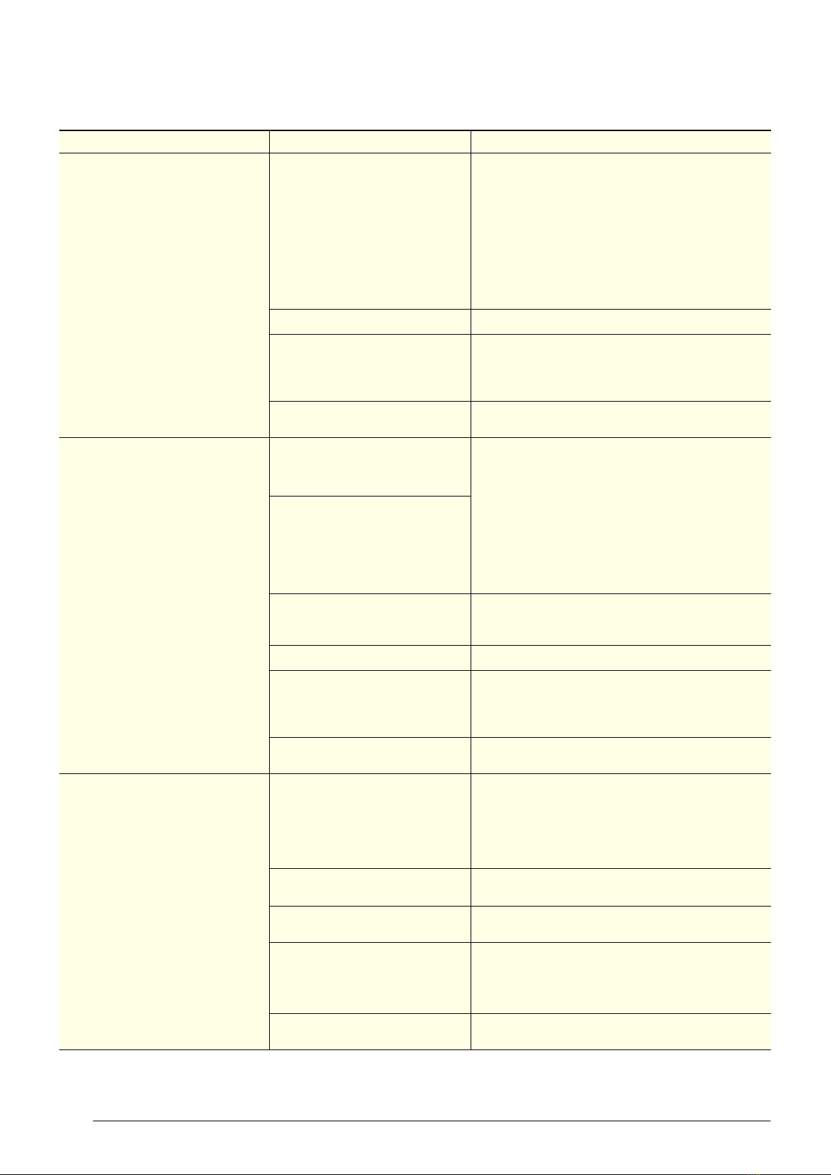
Table 4: Faults
Description Possible root cause Actions
Over-voltage protection
The maximum allowable mains supply
voltage has been exceeded. The
cabinet has temporarily shut down to
prevent damage and will restart once
the supply voltage decreases.
Should be a one-off. If it continues,
consider:
• poor line voltage
Test the incoming voltage to ensure it is correct. The
test voltage needs to be between 198 and 264 volts.
• If outside this, the controller will shut the system
down until the voltage returns to between these
measurements.
• If the voltage is correct and the controller is still
showing a fault, replace the controller.
• rural location
• voltage setting parameter
• Check the voltage parameter settings are between
198 and 264 volts. If this parameter is outside the
correct voltage, changing it may damage the
controller.
• controller • The controller may be reading incorrectly and need
replacing.
Under-voltage protection
The mains supply voltage has dropped
below the minimum allowable level.
The cabinet has temporarily shut down
to prevent damage and will restart once
the supply voltage increases.
Should be a one-off. If continues,
consider:
• power supply overloaded Test the incoming voltage to ensure it is correct. The
test voltage needs to be between 198 and 264 volts.
• If outside this, the controller will shut the system
down until the voltage returns to between these
measurements.
• If the voltage is correct and the controller is still
showing a fault, replace the controller.
• poor line voltage
• multi-box use
• Check that there are not too many plugs using the
same multi-box adaptor causing the voltage to
drop.
• rural location
• voltage setting parameter
• Check the voltage parameter settings are between
198 and 264 volts. If this parameter is outside the
correct voltage, changing it may damage the
controller.
• controller • The controller may be reading incorrectly and need
replacing.
High condensing temperature
protection
The system was operating at an
elevated temperature and has
temporarily shut down to prevent
damage. Extended operation in this
condition may result in ALARM 15,
increased energy consumption and a
reduction in cabinet life.
Cartridge swap is not required.
• Condenser not clean
• Remove and clean the condenser filter.
• Check that the condenser is free of debris.
• If the coil is dirty, clean it with a vacuum cleaner or
soft brush.
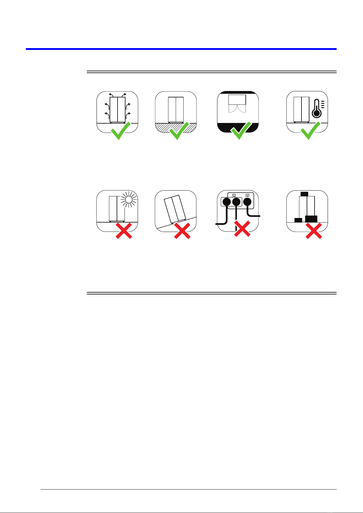
• Poor installation or ventilation • Check the installation guidelines.
• If fitted, check the rear stand-offs are extended.
• Condenser fan motor or blade • Check that the condenser fan blades are in place
and all condenser fans are operating correctly.
• Controller
The controller may be reading incorrectly and need
replacing.
• Confirm the temperature reading with an
independent thermometer.
• Very high ambient temperature • Check if the probes are faulty and reading
incorrectly.