Proton InteliSENS PD30 User manual


Page 2 of 68
Proton Products InteliSENS PD30 Instruction Manual (Issue 1a)
Table of Contents
DECLARATION OF CONFORMITY (CE)..........................................................5
INTRODUCTION..........................................................................................6
SPECIFICATIONS........................................................................................7
STANDARD INTERFACES ........................................................................................................................7
OPTIONAL INTERFACES..........................................................................................................................8
OPTIONAL FUNCTIONALITY.....................................................................................................................8
DIMENSIONAL DRAWINGS...........................................................................9
ANNOTATED DRAWINGS...........................................................................10
CONNECTORS.....................................................................................................................................10
OPTIONAL ACCESSORIES .........................................................................11
OPTIONAL INTERFACES........................................................................................................................11
Industrial bus interfaces .............................................................................................................................. 11
Electrical interfaces ..................................................................................................................................... 12
OPTIONAL FIRMWARE ..........................................................................................................................12
INTERFACE DISPLAY MODULES .............................................................................................................14
POWER SUPPLIES AND CONNECTIVITY ..................................................................................................14
INSTALLATION.........................................................................................15
PRECAUTIONS.....................................................................................................................................15
OPTICAL WINDOW CLEANING PROCEDURE.............................................................................................16
INSTALLATION SEQUENCE ....................................................................................................................16
MECHANICAL INSTALLATION................................................................................................................17
GAUGE HEAD DIMENSIONS:PD30........................................................................................................17
INSTALLATION NOTES: ....................................................................................................................................... 17
ELECTRICAL INSTALLATION..................................................................................................................17
Earth connection ......................................................................................................................................... 17
Shielded Cables ........................................................................................................................................... 17
Optional CDI4 interface display unit installation......................................................................................... 18
DC Power supply.......................................................................................................................................... 19
Powering on the gauge ............................................................................................................................... 19
Power indications........................................................................................................................................ 20
Powering off the gauge............................................................................................................................... 20
CONFIGURATION VIA CDI4.......................................................................20
POWER ON SCREEN.............................................................................................................................20
HOME PAGE 1.....................................................................................................................................21
HOME PAGE 2.....................................................................................................................................21
HOME PAGE 3.....................................................................................................................................22
HOME PAGE 4.....................................................................................................................................22
FUNCTION MENUS ...............................................................................................................................23
PRESET..............................................................................................................................................24
COMMUNICATIONS...............................................................................................................................29
INTERFACE......................................................................................................................................31
GAUGE INFORMATION..........................................................................................................................34
STORE................................................................................................................................................35
STATISTICS.........................................................................................................................................35
FFT ...................................................................................................................................................36
ACCESS LEVELS.............................................................................................................................37
STANDARD COMMUNICATIONS INTERFACES ...............................................38
CAN-BUS COMMUNICATIONS ...............................................................................................................38
CAN-bus interface ....................................................................................................................................... 38
CAN-bus LED indicator ................................................................................................................................ 38

Page 3 of 68
Proton Products InteliSENS PD30 Instruction Manual (Issue 1a)
RS-232 COMMUNICATIONS .................................................................................................................39
RS-232 interface .......................................................................................................................................... 39
RS-232 SINGLE LETTER PROTOCOL (SLP)..........................................................................................39
RS-422 /RS-485 COMMUNICATIONS...................................................................................................40
RS-422 / RS-485 interface ........................................................................................................................... 40
ETHERNET COMMUNICATIONS ..............................................................................................................40
Ethernet interface ....................................................................................................................................... 40
Ethernet LED indicator ................................................................................................................................ 41
OPTIONAL COMMUNICATIONS INTERFACES ................................................42
WIFI WIRELESS COMMUNICATIONS......................................................................................................42
WiFi interface .............................................................................................................................................. 42
PROFIBUS COMMUNICATIONS............................................................................................................42
PROFIBUS interface ..................................................................................................................................... 42
PROFIBUS LED indicator .............................................................................................................................. 42
PROFINET communications ......................................................................................................................... 43
PROFINET interface ..................................................................................................................................... 43
ETHERNET /IP COMMUNICATIONS........................................................................................................44
EtherNet / IP interface ................................................................................................................................ 44
EtherNet / IP LED indicator.......................................................................................................................... 44
STANDARD ELECTRICAL INTERFACES........................................................45
SPEED PULSE INPUT............................................................................................................................45
Speed pulse input connection...................................................................................................................... 45
ANALOGUE INPUT................................................................................................................................46
Analogue input connection ......................................................................................................................... 46
LOGIC INPUTS.....................................................................................................................................47
Logic inputs connection............................................................................................................................... 47
Logic inputs configuration........................................................................................................................... 48
Interrogating External Alarm 1 and External Alarm 2 Logic Input Status ................................................... 48
RELAY OUTPUTS.................................................................................................................................50
Relay outputs connection............................................................................................................................ 50
Relay outputs electrical specifications ........................................................................................................ 50
OPTIONAL ELECTRICAL INTERFACES.........................................................51
ANALOGUE OUTPUTS ..........................................................................................................................51
Analogue outputs connection ..................................................................................................................... 51
PI FEEDBACK CONTROLLER.................................................................................................................52
PI feedback controller connection ............................................................................................................... 52
PI feedback controller electrical specifications ........................................................................................... 52
PI feedback controller connection to production equipment ...................................................................... 53
INTERFACE CONNECTOR PIN OUTS.........................................................55
PROTON STANDARD PARAMETER ACCESS PROTOCOL .................................56
PARAMETER WORD FORMATS...............................................................................................................56
Bit pattern words ........................................................................................................................................ 56
Numerical value words................................................................................................................................ 56
Double length words ................................................................................................................................... 56
READING INPUT PARAMETERS..............................................................................................................56
Reading a single input parameter ............................................................................................................... 56
Reading a block of input parameters .......................................................................................................... 56
WRITING INPUT PARAMETERS...............................................................................................................57
Writing a single input parameter................................................................................................................ 57
READING OUTPUT PARAMETERS...........................................................................................................57
Reading a single output parameter ............................................................................................................ 57
Reading a block of output parameters........................................................................................................ 57
Reading a continuous stream of a single output parameter....................................................................... 57
Reading a continuous stream of a block of output parameters.................................................................. 58

Page 4 of 68
Proton Products InteliSENS PD30 Instruction Manual (Issue 1a)
MODBUS PARAMETER ACCESS PROTOCOL .................................................59
INPUT PARAMETERS.................................................................................60
OUTPUT PARAMETERS .............................................................................65
CONTACT DETAILS FOR ENQUIRIES,SALES AND SERVICE .............................68
WEB SITE............................................................................................................................................68
ENQUIRIES AND SALES.........................................................................................................................68
SERVICE ENQUIRIES............................................................................................................................68
MANUAL FEEDBACK AND COPYRIGHT ........................................................68

Page 5 of 68
Proton Products InteliSENS PD30 Instruction Manual (Issue 1a)
DECLARATION OF CONFORMITY (CE)
Proton Products International Limited declares that the equipment listed below fulfils the requirements
of directive EMC: 2014/30/EU and Low Voltage: 2014/35/EU.
The following standards were applied:
Radio -ETSI EN 300 328 V2.1.1 (2016-11)
EMC - EN 61326-1:2013
Low Voltage - EN 61010-1:2010 (Scientific and measuring instruments)
Health and Safety - EN 60950-1:2006+A11:2009+A1:2010+A12:2011+A2:2013, EN 62311:2008
Equipment Covered
Product name
Description
Part number
PD30
Single Axis diameter gauge
00054MC021
SiDi-CDi4
Colour touch screen display interface
00049MC021
These products carry the CE Mark:
Warning –laser equipment
The diameter gauge contains a laser source that complies with EN60825 Class 2 under normal use. If
the gauge is opened, the laser source removed and tampered with then the source can become Class
3.
The manufacturer of the above named equipment is:
Proton Products International Limited
10 Aylesbury End
Beaconsfield
Bucks
HP9 1LW
ENGLAND
Proton Products is an ISO9001:2015 registered company.
The declaration is signed by:
Paul Sives ………………………
Page 6 of 68
Proton Products InteliSENS PD30 Instruction Manual (Issue 1a)
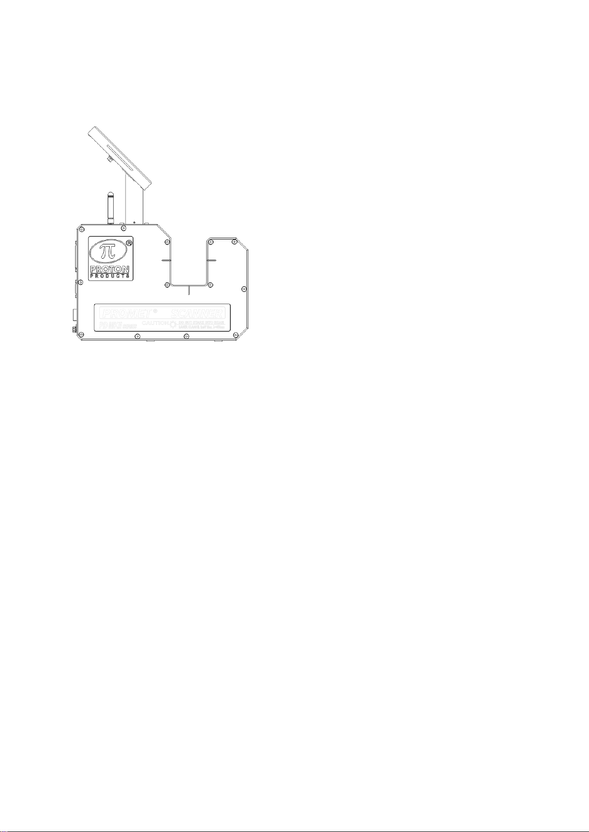
INTRODUCTION
GAUGE PD30 WITH CDI4 DISPLAY
The InteliSENS PD30 Single Axis Laser Scanning Diameter Gauge provides fast, accurate and
repeatable diameter measurements of cables or other objects manufactured in a continuous process.
The PD30 measures objects or cables up to 30 mm in diameter, by a non-contact method. The
gauge contains a single-axis optical scanning system and a processing circuit to produce diameter
and statistical data.
When fitted with the optional CDI4 interface display unit, the InteliSENS PD30 diameter gauge can
operate as a standalone unit.
RS-232, RS-422, RS-485 and Ethernet communication interfaces are installed as standard for
straightforward connection to computers or PLCs. Optional industrial standard communication
interfaces (PROFIBUS, PROFIBNET, EtherNet/IP or WiFi) can be specified for installation at time of
manufacture.
Analogue and pulsed line speed inputs are fitted as standard to provide line speed data to the gauge
for optional PI feedback control and SMFD (Single Measurement Flaw Detection).
User configurable logic inputs are provided as standard to reset gauge measurements and trigger
printing. User configurable relay outputs are provided as standard to signal gauge status, lump and
neck detection and measurements exceeding preset error limits.

Page 7 of 68
Proton Products InteliSENS PD30 Instruction Manual (Issue 1a)
SPECIFICATIONS
PD30 specifications
Number of axes
1
Scan rate
600 scan/s/axis
Cumulative scan rate
600 scan/s
Update time
1.667ms
Object diameter
0.1~27 mm
Optical gate diameter
30 mm
Accuracy
±(1μm + 0.008% of object diameter) μm
Output resolution
1 μm
Operating temperature
5 ~ 45°C
Environmental protection
IP65
DC Power supply voltage
18~30VDC
DC Power consumption
30W
Light source
Laser (class 2)
Air wipe
Integrated air wipe system
Measurement units
(user configurable)
millimetres (line speed: millimetres / minute, length: metres)
inches (line speed: feet / minute, length: feet)
Measurement modes
Solid
Solid object diameter
Glass
Transparent object diameter
Helix
Twisted / braided multi-core cable envelope diameter
STANDARD INTERFACES
2x digital inputs
User configurable function
Reset, Print Activation
Maximum input voltage
24 Vdc
4x relay outputs
User configurable function
Gauge OK, Upper tolerances exceeded,
Lower tolerances exceeded, Single
Measurement Flaw Detection (SMFD)
Isolated contact rating
Maximum voltage
24 Vdc
Maximum current
1 A
Line speed inputs
Analogue input
0 - 10 Vdc, user scalable (only when PID
function is available).
Speed pulse input
250 kHz max frequency, 30 V or 50 V max
pulses (on two distinct inputs), user
scalable
Communication interfaces
RS-232*, RS-422, RS-485, CAN-bus**, Ethernet
*An optional RS-232-to-USB converter cable is available for connection to USB equipped computers.
**CAN-bus protocol is proprietary and reserved for connection to other Proton Products equipment
such as a CDI4 interface display unit.

Page 8 of 68
Proton Products InteliSENS PD30 Instruction Manual (Issue 1a)
OPTIONAL INTERFACES
3x Analogue outputs
±10 Vdc output of diameters or errors, user scalable
Communication interfaces
WiFi*
PROFIBUS, PROFINET or EtherNet/IP.
OPTIONAL FUNCTIONALITY
PI feedback controller
Proportional Integral feedback controller
Statistics
Maximum, minimum, mean, standard deviation, Cp, Cpk
SPC
Statistical Process Control automatic set point for PI feedback
controller (requires PI feedback controller option)
FFT
Fast Fourier Transform analysis for amplitude and frequency of
periodic diameter variations
SMFD
Single Measurement Flaw Detection (Lump and Neck detection)

Page 9 of 68
Proton Products InteliSENS PD30 Instruction Manual (Issue 1a)
DIMENSIONAL DRAWINGS
Page 10 of 68
Proton Products InteliSENS PD30 Instruction Manual (Issue 1a)
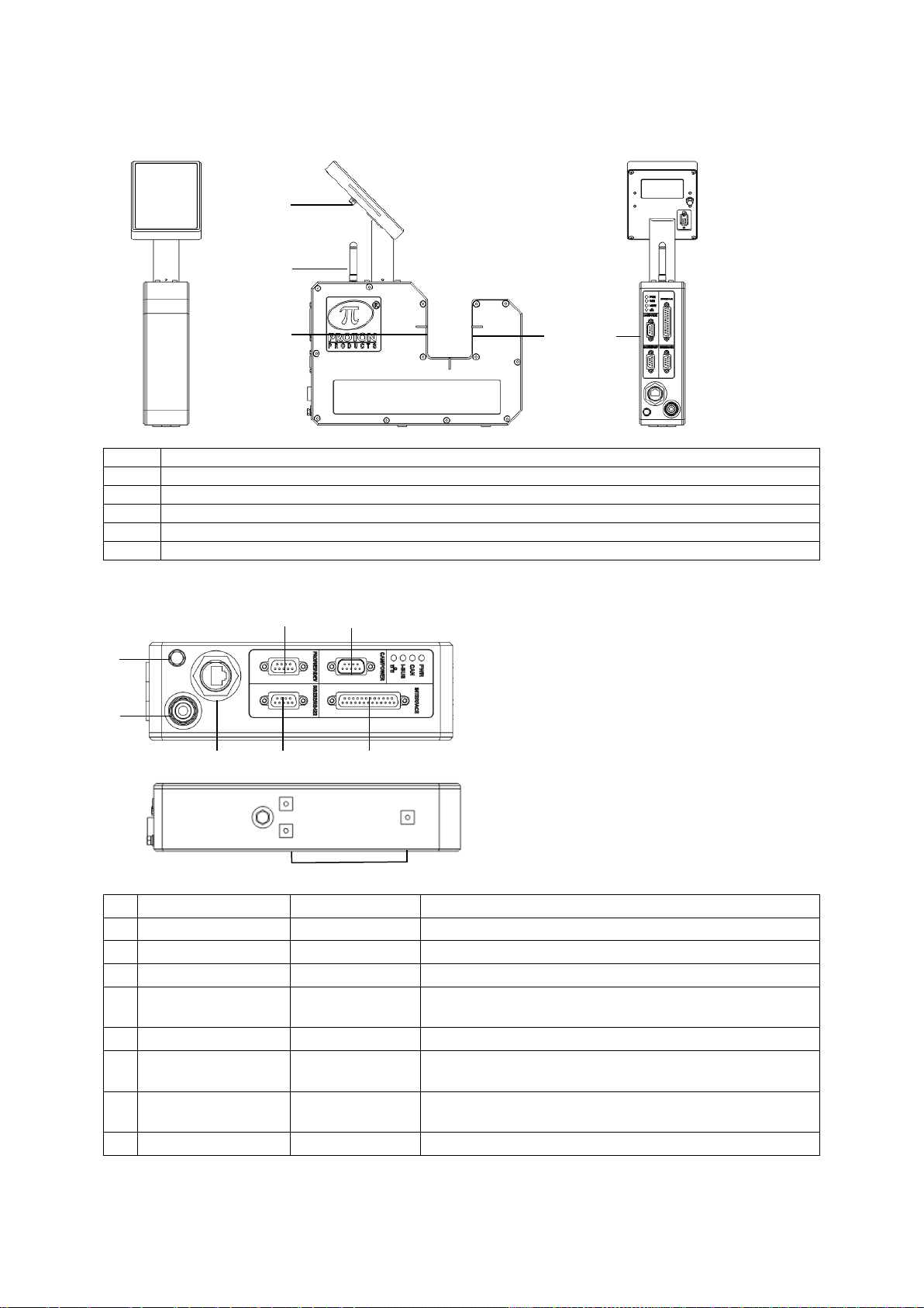
ANNOTATED DRAWINGS
Label
Description
1
Optional CDI4 interface display unit.
2
WiFi antenna
3
X-axis detector window.
4
X-axis light source window.
5
Connector panel.
CONNECTORS
Designation
Connector type
Description
1
Air wipe air inlet
6mm push-fit
Air wipe air inlet for optical windows
2
Earth bolt
M5 bolt
Earth point for the gauge enclosure
3
Ethernet
RJ45 socket
Ethernet communications interface
4
PROFI / EIP / DEV
DB9 female
Optional PROFIBUS, EtherNet/IP, PROFINET
communications interfaces
5
RS232 / 485
DB9 female
RS-232, RS-422/485 communications interface.
6
CAN / POWER
DB9 male
CAN-bus communications interface and DC power
input
7
INTERFACE
DB25 female
Logic and speed pulse inputs, relay outputs, optional
analogue input, optional PI feedback controller I/O
8
Mounting holes
M5 x 10 mm
Securely mount the gauge before operation.
3
2
4
5
1
2
3
4
5
6
7
8
1

Page 11 of 68
Proton Products InteliSENS PD30 Instruction Manual (Issue 1a)
OPTIONAL ACCESSORIES
OPTIONAL INTERFACES
The WiFi wireless interfaces may be specified for installation at time of order placement; cannot be
field-retrofitted.
WiFi wireless interface
For wireless configuration and monitoring of the gauge from
smart phones, tablet and laptop PCs.
Proton part number
00054MC067
Industrial bus interfaces
Only one of the following 3 industrial bus interfaces may be specified for installation at time of order
placement; cannot be field-retrofitted.
PROFIBUS interface
For connection to PLCs and other process control
instrumentation via an industry-standard PROFIBUS
network.
Proton part number
00054MC062
PROFINET interface
For connection to PLCs and other process control
instrumentation via an industry-standard PROFINET
network.
Proton part number
00054MC063
EtherNet/IP interface
For connection to PLCs and other process control
instrumentation via an industry-standard EtherNet/IP
network.
Proton part number
00054MC064
RJ45 to DB9 converter
For connecting a RJ45 8P8C terminated network cable to
the DB9 industrial bus port.
Comes as a pair for connecting to either type A or type B
terminated network cables.
Proton part number
00041MC048
Page 12 of 68
Proton Products InteliSENS PD30 Instruction Manual (Issue 1a)
Electrical interfaces
Must be specified for factory installation at time of ordering; cannot be field-retrofitted.
Analogue outputs
3x analogue (±10V) outputs.
Independently programmable functions for X, Y, Z
(DG3030/3060 only) diameters, average diameter, diameter
errors from preset value, ovality and ovality error.
Proton part number
00047MC062
Proportional Integral (PI) feedback controller
PI feedback diameter control via adjustment of insulation
extruders or capstan drives.
Isolated ±20V analogue input and ±10V analogue output for
connection to insulation extruders or capstan drives.
Proton part number
00047MC061
OPTIONAL FIRMWARE
Optional firmware may be end-user enabled through the purchase of a license key. Some optional
firmware functions are dependent on the presence of optional interfaces.
Fast Fourier Transform (FFT) Analysis
FFT
Calculates FFT frequency spectra of measured diameters.
Identifies periodically occurring diameter fluctuations caused
by production line problems.
Essential for telecommunications cable lines where periodic
diameter fluctuations can degrade cable bandwidth.
Proton part number
00054SW013
Statistical Process Control (SPC) automatic set point control
Minimises insulation material consumption whilst holding the
insulation diameter in tolerance.
Requires the PI feedback controller interface option
(00047MC061) to be installed.
Proton part number
00054SW011
Single Measurement Flaw Detection (SMFD)
High-speed lump and neck flaw detection.
Proton part number
00054SW014

Page 13 of 68
Proton Products InteliSENS PD30 Instruction Manual (Issue 1a)
PCIS_DG
PC Interface Software
PC-based software package.
User-friendly graphical user interface.
Displays all measurements.
Provides menu-based setting of all parameters.
Provides data logging, presets and alarms.
Connection via RS-232, Ethernet or EtherNet/IP.
Proton part number
00054SW015

Page 14 of 68
Proton Products InteliSENS PD30 Instruction Manual (Issue 1a)
INTERFACE DISPLAY MODULES
SiDi-CDi4
Touch screen display module
Touch screen display.
Connects via the CAN-bus port.
Displays measured speed and length.
Provides menu-based setting of all parameters.
Mounts directly on the gauge body or remotely via an
extension cable.
Proton part number
00049MC023
POWER SUPPLIES AND CONNECTIVITY
PSU-BOB-DG
Power supply and break-out box
Connects via the DB25 “INTERFACE” connector.
Supplies 24VDC electrical power to the gauge.
Provides screw terminal access to all “INTERFACE”
connector input and output pins.
End user cables are sealed with three cable glands.
Input voltage range: 90 –260 VAC @ 45 –65 Hz.
Select the required length of DB25 cable from below.
Proton part number
00047MC660
Terminal Strip-DIN
Breaks out the DB25 “INTERFACE” connector to a DIN
rail mountable set of screw terminals.
Select the required length of DB25 cable from below.
Proton part number
00041MC730
DB25 “INTERFACE” port to PSU-BOB-DG, Terminal Strip-DIN cable
Length / m
Proton part number
3
00041CT003
5
00041CT005
10
00041CT010
20
00041CT020
30
00041CT030

Page 15 of 68
Proton Products InteliSENS PD30 Instruction Manual (Issue 1a)
INSTALLATION
PRECAUTIONS
Operating temperature
Specification
Minimum
Typical
Maximum
Units
Operating temperature
+5
+45
°C
Do not operate the gauge in temperatures outside of the specified range.
Do not install the gauge near high temperature surfaces or objects which may cause it to
overheat.
Operation of the gauge outside the specified temperature range may result in degraded
measurement accuracy, malfunction or damage to the gauge.
Protect from impact
The gauge contains delicate optical and electronic assemblies and must never be dropped or
struck by other objects.
The gauge must be securely mounted by its base to prevent toppling.
Measured objects threaded through the optical gate cavity must be secured against contact
with the optical windows or catching upon the gauge body. For cable production line
applications, Proton Products can supply optional adjustable cable guides for securing the
passage of a cable through the optical gate cavity.
Do not open or disassemble
The gauge contains no user serviceable components.
Loosening the gauge screws or removing its cover will invalidate the product warranty.
Periodic maintenance
The physical condition of the gauge, optional CDI4 interface display unit and connecting
cables should be checked periodically; if any damage is suspected, then the unit should be
taken out of service for inspection and repair or replacement of damaged parts.
Optical windows
Do not allow smoke, water, steam, dust or other debris to come into contact with any of the
optical windows.
Obstruction of the optical windows may degrade measurement accuracy or inhibit
measurement.
If any optical window appears to be damaged or misaligned, then the unit should be taken out
of service for repair.
If any optical window requires cleaning, then refer to the cleaning procedure detailed in this
manual to minimise the risk of scratching the windows.

Page 16 of 68
Proton Products InteliSENS PD30 Instruction Manual (Issue 1a)
OPTICAL WINDOW CLEANING PROCEDURE
The optical windows are manufactured from anti-reflection coated optical glass; they must be
treated with the same level of care as a high-performance camera lens.
Before inspecting or cleaning the optical windows, ensure that the gauge is powered
off and no light is emitted.
Required items
Notes
Small blower brush
Such as the type used to remove dust from camera lenses.
Lens cleaning tissues or
micro-fibre lens cleaning cloth
Do NOT use facial tissues as these can scratch delicate optics.
Lens cleaning solution
Such as the type specified for cleaning camera lenses.
1. Use the small blower brush to remove any visible dust on the optical window.
2. Apply a few drops of lens cleaning solution to a fresh lens cleaning tissue or a clean micro-
fibre lens cleaning cloth.
3. Gently wipe the optical window from the centre outwards; apply only light pressure to the
tissue or cloth when wiping the optical window.
4. Repeat as necessary with fresh tissues or a clean section of cloth until the optical window is
clean and free of all smears and smudges.
INSTALLATION SEQUENCE
Unpack the gauge and check for missing accessories and shipping damage.
Mechanical installation:
1. Mount the gauge securely on a user supplied platform using the four mounting brackets.
Electrical installation:
1. Install earth connections.
2. Install optional CDI4 interface display unit.
3. Depending on the model, install either an AC power cable or DC power supply (such as an
optional Proton Products PSU-UNI, PSU-BOB or PSU-CAN power supply).
4. Install interface connections (RS-232, RS-422/485, Ethernet or optional PROFIBUS,
EtherNet/IP or WiFi antenna).
5. Install speed input (analogue or pulse).
6. Install optional electrical interfaces (Logic inputs, Relay outputs, Analogue outputs, PI
feedback controller connections) using the optional Proton Products PSU-BOB breakout box
or terminal strip.
7. Configure the gauge either via an optional CDI4 interface display unit or any of the above
interfaces.
Page 17 of 68
Proton Products InteliSENS PD30 Instruction Manual (Issue 1a)
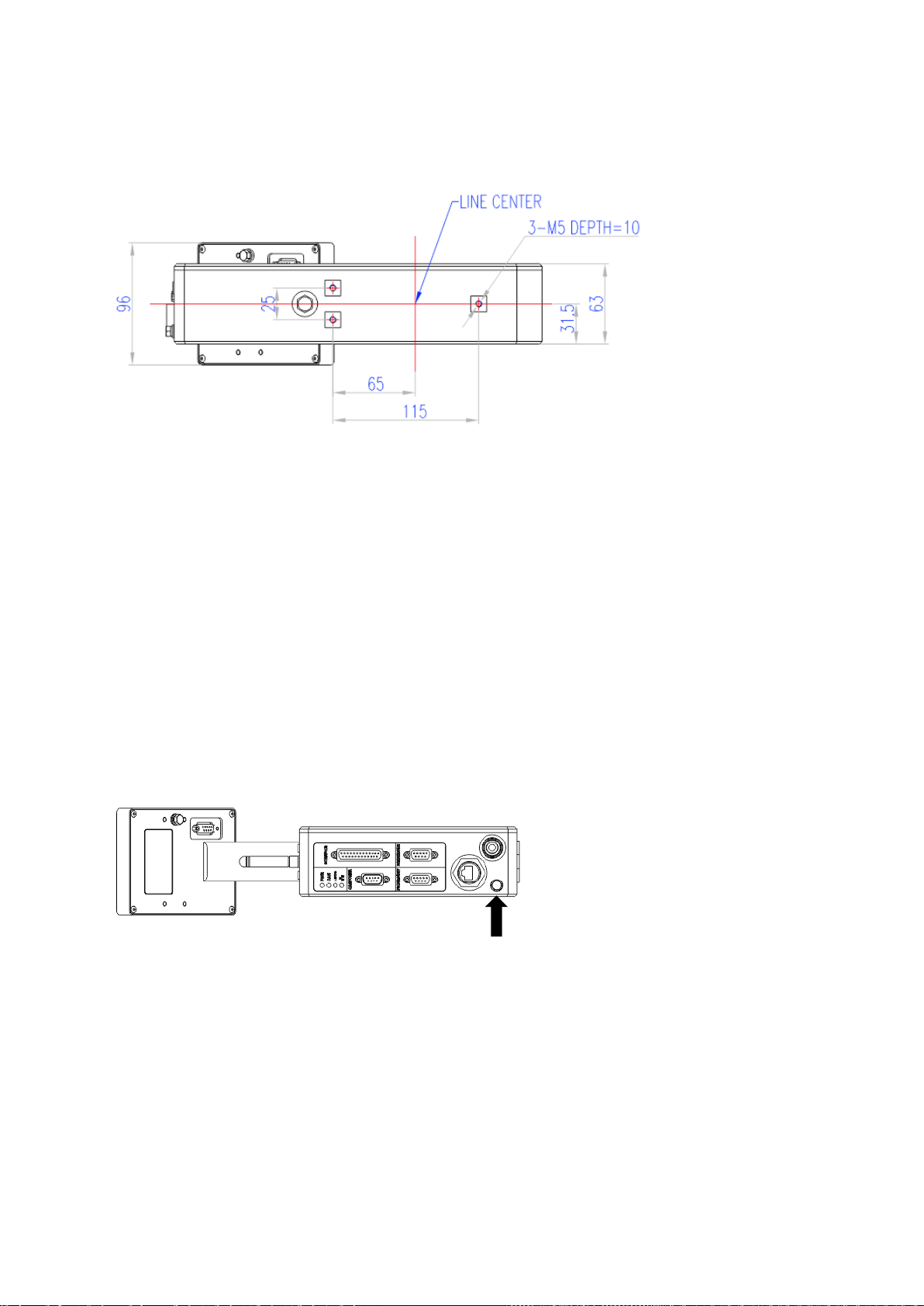
MECHANICAL INSTALLATION
GAUGE HEAD DIMENSIONS:PD30
INSTALLATION NOTES:
Do not open the gauge or loosen the cover screws.
Do not overtighten the fixing screws.
Do not use fixing screws that are too short or long. The correct screws [M5 by 16] are supplied
with the gauge head for mounting it to the HST3 height stand which has a thickness of 8mm. If a
stand of different thickness is used then the screw length supplied may not be suitable.
Do not place in a position close to a hot surface.
Do not allow the cable being measured to touch the gauge head.
If a large cable is being measured then ensure that it is supported so that the cable end does not
catch on the gauge.
Ensure that the cable alignment is perpendicular to the face of the gauge with the least error
practically possible, an angle error of one degree gives a measurement error of 0.013%, at two
degrees this becomes 0.05%.
ELECTRICAL INSTALLATION
Earth connection
Connector type: M5 bolt
An earth wire of at least 6mm2must be attached via a crimp on ring terminal to the dedicated
M5 earth bolt on the case of the gauge.
Do not rely on the mounting bolts to provide a reliable earth path.
If a height stand is used then it must also be earthed via its own dedicated earth wire.
All earth wires should be kept as short as practical.
Shielded Cables
Use shielded cable for all signal connections.
Ensure that all cable shields are correctly clamped and electrically connected to their
connectors and metal connector shells at both ends.

Page 18 of 68
Proton Products InteliSENS PD30 Instruction Manual (Issue 1a)
Ensure that the shields of cables connecting to the end user’s equipment are clamped to
earth at their destination.
Optional CDI4 interface display unit installation
The CDI4 interface display unit is a recommended optional accessory with the following features:
Menu based user interface for configuring the gauge and displaying measurements and error
messages.
Two versions of the CDI4 interface display are available: one version that mounts directly on
the gauge body and one version that can be connected remotely via a CAN-bus extension
cable.
The remote CDI4 interface display unit can also power DC powered gauges through a CAN-
bus port connected power supply.
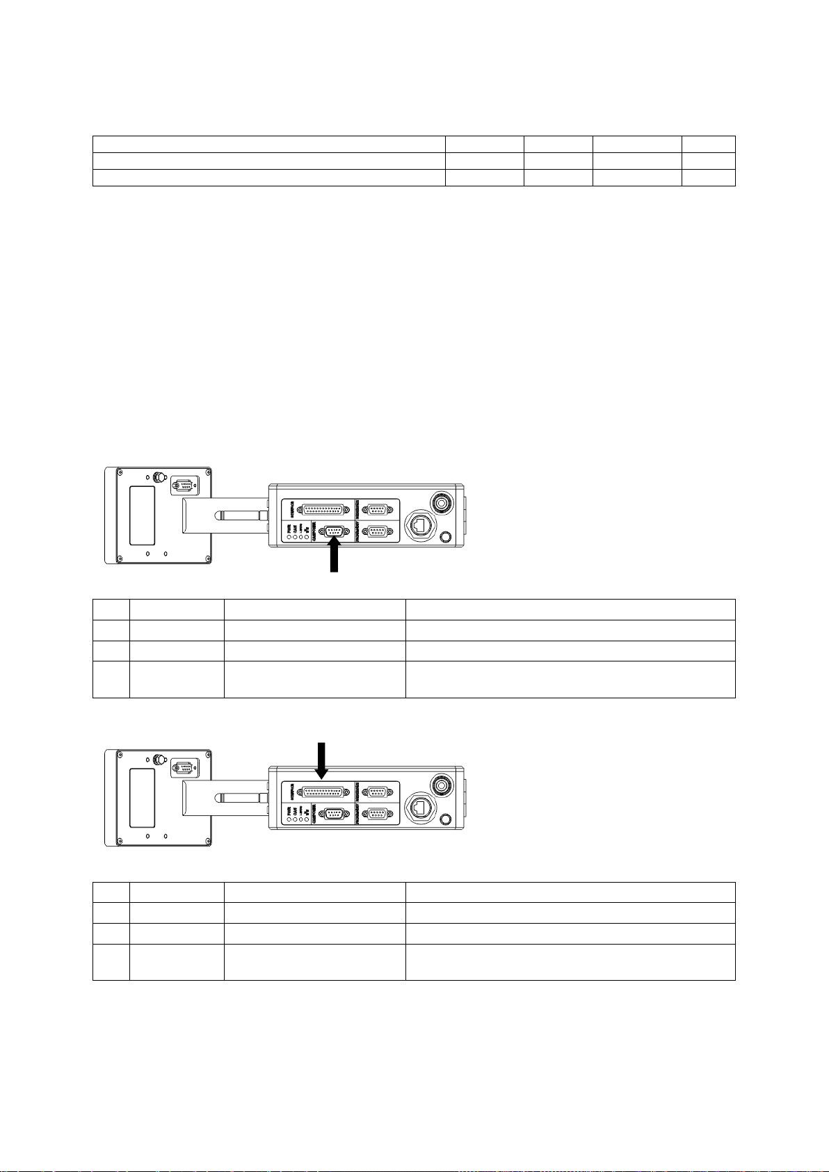
Installing a CDI4 display unit to PD30 gauge head:
1
Unscrew the four screws and remove the CDI4
port blanking plate.
Store the blanking plate and four countersunk
screws for future use.
2
Align the CDI4 connector mating key with
the port socket and insert.
Secure the CDI4 unit with four spring
washers and M4 cap head screws.
Installing a remote CDI4 interface display unit:
1. Connect the remote CDI4 interface display unit to the CAN/POWER connector using a CAN-
bus extension cable.
2. Connect an optional PSU-CAN mains power supply unit to the second CAN-bus port on the
remote CDI4 interface display unit.
Page 19 of 68
Proton Products InteliSENS PD30 Instruction Manual (Issue 1a)
DC Power supply
Specification
Minimum
Typical
Maximum
Units
Power supply voltage*
15
24
30
VDC
Power consumption (with optional CDI4 display unit)
30
W
*If a long power supply cable with a significant voltage drop is used, then ensure that the voltage at
the gauge connector does not fall below the minimum value.
Power may be supplied to the gauge via the following optional accessories:
Remote CDI4 interface display unit connected to the “CAN / POWER” connector.
PSU-CAN Power supply unit connected to the “CAN / POWER” connector.
PSU-UNI Power supply unit connected to the “INTERFACE” connector.
PSU-BOB Power supply unit and break out box connected to the “INTERFACE” connector.
Alternatively, power may be directly supplied to the gauge via either of the following connectors:
“CAN / POWER” connector.
“INTERFACE” connector.
“CAN / POWER” Connector
Connector type: DB9 male (plug)
Pin
Designation
Description
Notes
3
REG.GND
Power supply ground (0 V)
9
+24V
+24 V power supply
S
Shield
Ensure that the cable shield is connected to this
via the plug shield connection.
“INTERFACE” Connector
Connector type: DB25 female (socket)
Pin
Designation
Description
Notes
24
REG.GND
Power supply ground (0 V)
25
+24V
+24 V power supply
S
Shield
Ensure that the cable shield is connected to this
via the plug shield connection.
Powering on the gauge
The gauge has no power switch; as soon as power is applied it will power up, perform self tests and
then commence measurement.

Page 20 of 68
Proton Products InteliSENS PD30 Instruction Manual (Issue 1a)
Power indications
PWR
LED status
Indication
Continuous red
Gauge is powered on
Power
Extinguished
Gauge is powered off
If an optional CDI4 interface display is attached to the gauge, then correct power up is indicated by
the display of the welcome screen followed by the home page.
Powering off the gauge
The gauge has no power switch; it may be powered off by switching off or disconnecting the power
supply to the unit.
CONFIGURATION VIA CDI4
Power on screen
When the gauge is powered on, the Proton welcome
screen will be displayed momentarily.
Table of contents
Other Proton Laundry Accessories manuals


