Provia ASPECT User manual

INSTALLATION INSTRUCTIONS
3-LITE VINYL PATIO DOOR
END ACTIVE, UNASSEMBLED
(ASPECT™ AND ENDURE™)
Contact the local recycling waste management center for waste disposal in the area. Always
check local waste requirements and carefully dispose of waste in accordance with Federal
and other regulations.
Homes built before 1978 may contain lead paint. All replacement installations must comply
with the U.S. EPA’s Lead-Based Paint Renovation, Repair, and Painting Program (RRP Rule).
Read more about the RRP Rule and lead-safe work practices, on the U.S. EPA’s website at:
www.epa.gov/lead
* Find QR Codes inside for additional information,
helpful installation tips, and videos.
ATTENTION!
YOU CAN ALSO SCAN
THE PACKAGING QR CODE
TO ACCESS THIS DOCUMENT
Printed instructions included
with each product will be
phased out in the
near future
1
• Tape Measure
• Pencil
• Shims
• Drill & Drill Bits
• Utility Knife
• Hammer or Mallet
• Flat-Head Screwdriver
• Phillips Screwdriver
• Level
• High Quality Silicone Caulking in accordance with
ASTM C 920, Class 25 & Caulking Gun.
•AAMA approved Low-Expanding Window Insulation
Foam in accordance with ASTM C, 1620.
•6" or 9" Adhesive Flashing Tape in accordance with
ASTM D-779 (new construction application)
GETTING STARTED
TOOLS & MATERIALS YOU WILL NEED
REMEMBER: ALWAYS USE THE APPROPRIATE PERSONAL PROTECTIVE EQUIPMENT.
Read these instructions carefully before starting installation. Product warranty does not cover damages
resulting from improper installation.
IMPORTANT NOTES BEFORE YOU BEGIN
• Inspect your package for any visible damages to the product. In addition, double check your paperwork
with label on product(s) and verify all information is a match. Open packaging to confirm style, color, handing
and that order was shipped complete. Double check size of new unit by comparing it for fit to opening. If
damages or irregularities are found, please document with pictures and call Customer Service, 1-800-669-4711.
• If you have ordered optional items, verify that they are included in packaging contents. This includes checking
for multiple packages (For example, 1 of 2 and 2 of 2).
2
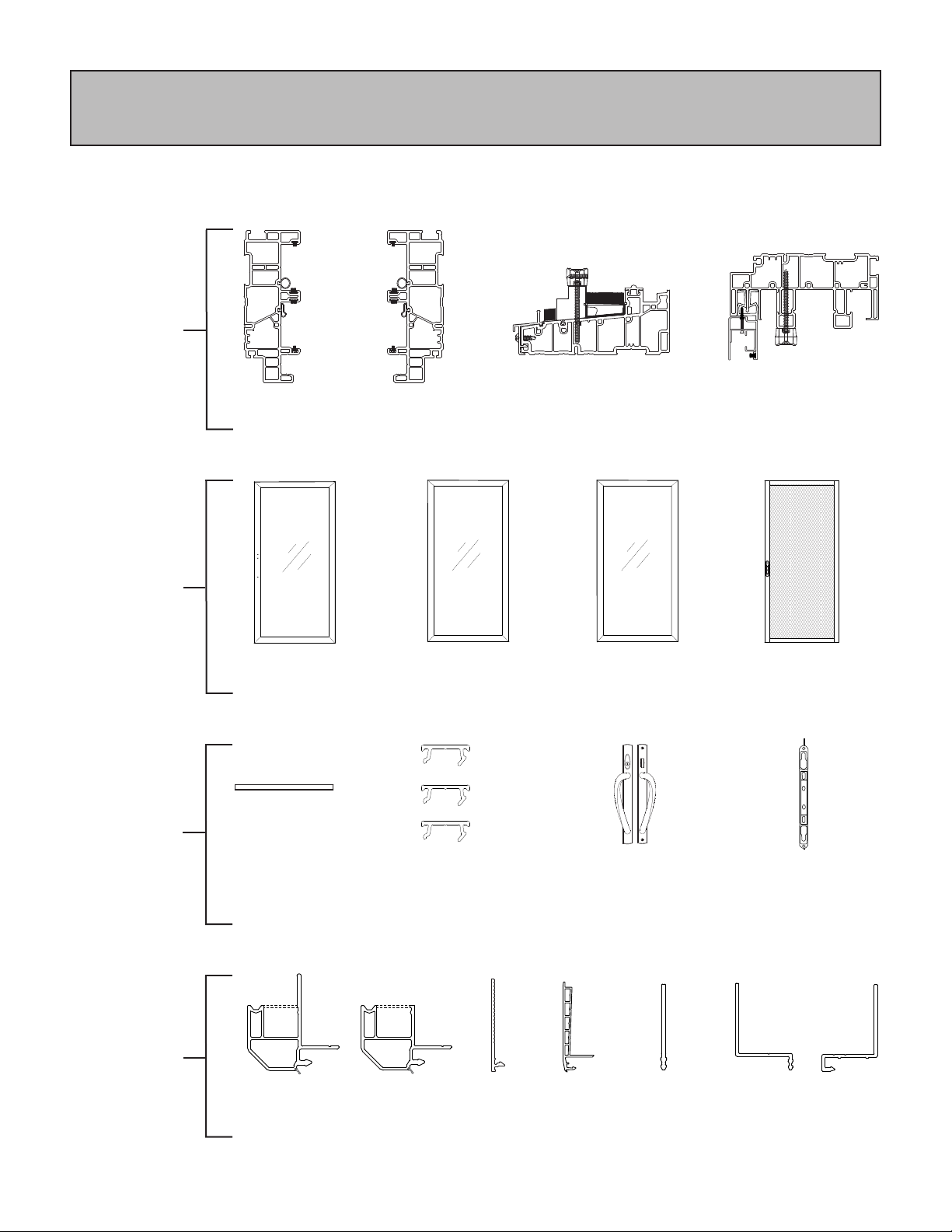
ASPECT™AND ENDURE™
3-LITE END ACTIVE PATIO DOOR ASSEMBLY CONTENTS
NOTE: Please refer to chart below for the required assembly contents of an Aspect or Endure patio door.
The patio frame will arrive from the factory unassembled with a few pre-assembled components to allow for
proper handing of the patio unit as ordered.
Main Frame
Assembly
Profiles
Sash and
Screen
(2) Exterior Vinyl
Jamb Cover
(2" x 80")
(1) Header Assembly
(1) Sill Assembly with Sill
Dust Cover factory installed
(1) Handle Set
(Aeris/ Endure Handle
Set shown)
(1) Mortise
Handle Set Keeper
(Taped to Active Sash)
(1) Active Sash (1) Fixed Sash
with interlock on
each stile
(1) Screen
Accessory
Parts
Optional
Installation
Accessories
(Refer to the
separate and
included instruction
document if
applicable)
5917
Brickmold
5907
Brickmold
w/ Nail Fin
5940
Nail Fin
(Partial Jamb)
5956
Nail Fin
5945
Nail Fin
(Full Jamb)
5938
Stucco
Flange
(1) Fixed Jamb
Assembly
5927
Frame
Adapter
5907 5917 5956
5928
5892 Interior Trim5840
5945
5940 5938 5927
5907 5917 5956
5928
5892 Interior Trim5840
5945
5940 5938 5927
5907 5917 5956
5928
5892 Interior Trim5840
5945
5940 5938 5927
5907 5917 5956
5928
5892 Interior Trim5840
5945
5940 5938 5927
5907 5917 5956
5928
5892 Interior Trim5840
5945
5940 5938 5927
5907 5917 5956
5928
5892 Interior Trim5840
5945
5940 5938 5927
5907 5917 5956
5928
5892 Interior Trim5840
5945
5940 5938 5927
(1) Fixed Jamb
Assembly
(3) Interior Vinyl
Groove Cover
(Ships installed on frame)
(1) Fixed Sash
with interlock on
(1) stile
3
ASPECT™AND ENDURE™
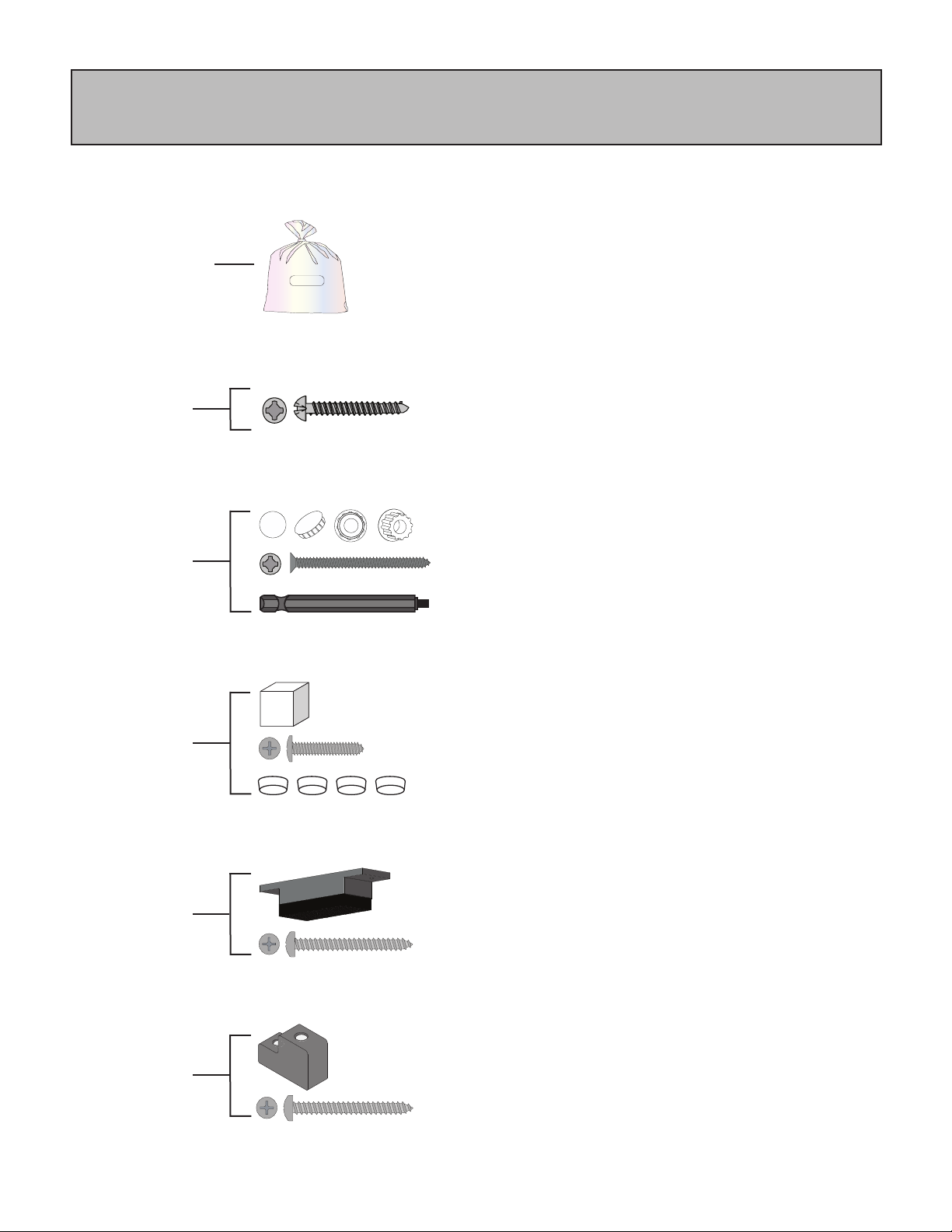
3-LITE END ASSEMBLY INSTALLATION PACK CONTENTS
NOTE: The individual installation packs are labeled and numbered. Please refer to the chart below for the
appropriate pack contents and for the installation location.
3⁄8" Hole Plugs (Color Matched), Part #: S-HG-698-CC
#8 x 3" Phillips Square Screws, Part #: S-HS-350-00
#2 Phillips Square Combo Bit, Part #: S-ST-347
Foam Plugs, Part #: S-HG-521-01
#8 x 1" Phillips Pan Head Screws, Part #: S-HS-345-00
Head Weatherstrip Block, Part #: S-HG-524-13
#8 x 11⁄4" Phillips Pan Head Screws, Part #: S-HS-342-13
Sash Stop (Bumper), Part #: S-HG-532-13
#8 x 11⁄4" Phillips Pan Head Screws, Part #: S-HS-342-13
(1) Installation
Pack #2
S-DH-020S-CC
(Jambs & Header)
(2) Installation
Pack #3
S-DH-023S-CC
(Fixed Sashes)
(2) Installation
Pack #4
S-DH-024S
(Header Block)
(1) Installation
Pack #5
S-DH-025S
(Header Bumper)
Parts
The individual installation packs are labeled, numbered
and are all packed inside one main bag. Open up the
main parts bag and refer to the appropriate pack contents
for each installation location referenced below.
3-Lite End Active
Installation Pack
S-DH-042S-CC
(16)
(16)
(1)
(4)
(4)
(1)
(2)
(1)
(2)
(1)
#8 x 2” Phillips Square Stainless Steel Screws,
Part #: S-HS-344-00
(2) Installation
Pack #1
S-HS-344S-CC
(Frame Assembly)
(10)
Screw Caps, Part #: S-HS-311-CC
(4)
4
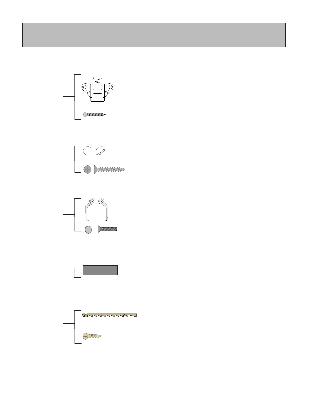
(1) Installation
Pack #10
S-DH-010S
(Screen)
Screen Wheel Brackets,
Part #: S-HG-366P-00 (Right Hand)
Part #: S-HG-367P-00 (Left Hand)
#6-32 x 7⁄8" Phillips Flat Head Screws, Part #: S-HS-360-00
(1)
(1)
(2)
AccuVent Bolt Plate (Color Matched), Part #: S-HG-573-CC
#8 x 1 Combo Vinyl Hold (Color Matched),
Part #: S-HS-340-CC
(1)
(2)
(1) AccuVent™
Bolt Plate Kit
S-HG-573S-CC
(Standard on Endure,
Optional on Aspect)
Active Sash Secondary Lock (Foot Lock) (Color Matched),
Part #: S-HG-353-CC
#8 x 3⁄4” Phillips Oval Head Screws (Color Matched),
Part #: S-HS-414-CC
3-Lite Shims, Part #: S-HG-542-13
(1) Installation
Pack #6
S-DH-026S-CC
(Standard on Aspect,
Optional on Endure)
(1) Installation
Pack #14
S-HG-54S-13
(Sill of Fixed Sash)
(1)
(4)
(4)
ASPECT™AND ENDURE™
3-LITE END ASSEMBLY INSTALLATION PACK CONTENTS
NOTE: The individual installation packs are labeled and numbered. Please refer to the chart below for the
appropriate pack contents and for the installation location.
(1) Installation
Pack #8
S-DH-028S-CC
(Screen Mullion)
NOT USED with
END ACTIVE
Screw Cap Cover (Color Matched), Part #: S-HG-534-CC
#8 x 1" Phillips Flat Head Screws, Part#: S-HS-351-00
(5)
(5)
5
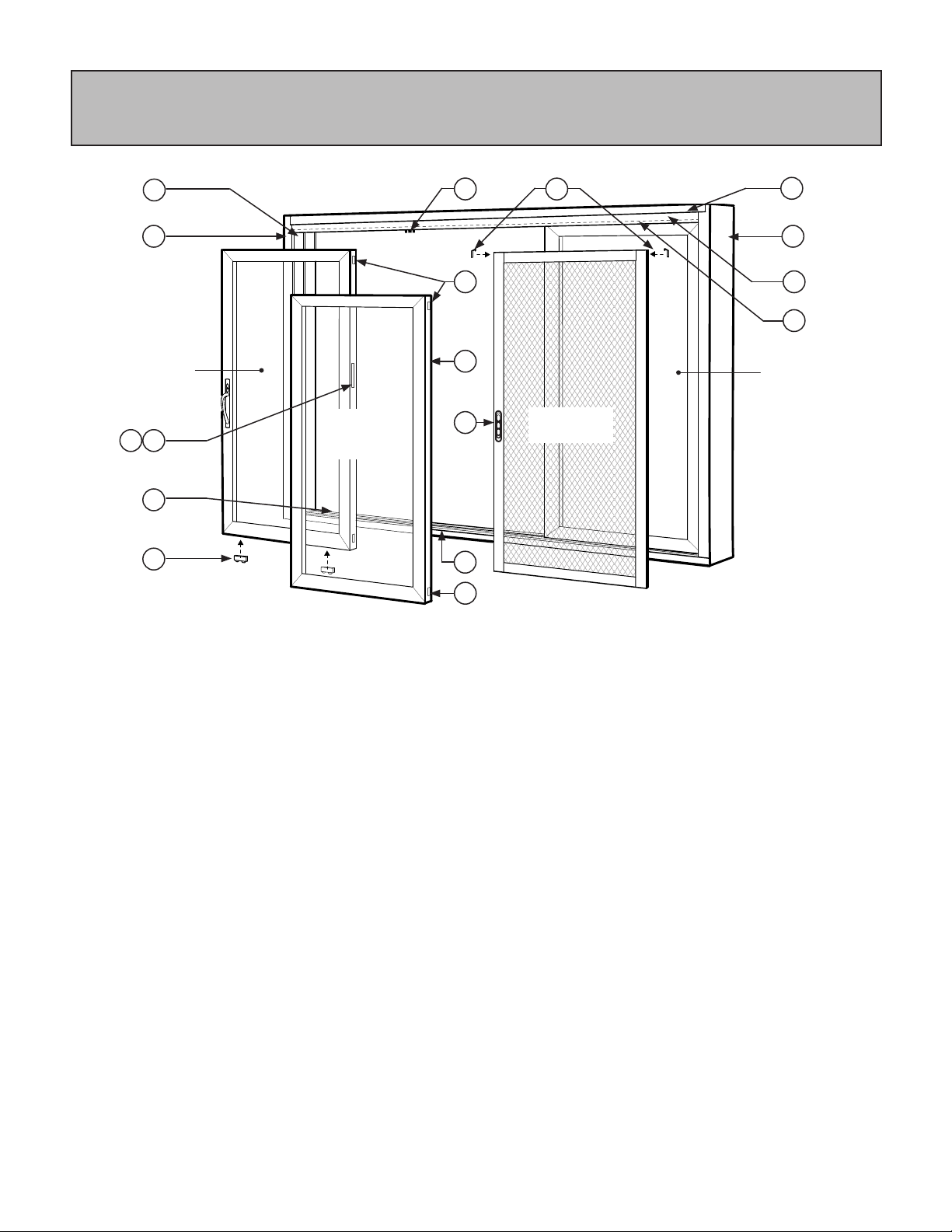
RE-ORDER REFERENCE - PRODUCT PART # IDENTIFICATION
NOTE: Parts listed may be a subassembly or part of a subassembly.
SCREEN PARTS:
O. LH Common Patio Screen Handle - S-DH-071
(RH Common Patio Screen Handle - S-DH-068)
P. LH Wheel Bracket Assembly - S-HG-367P-00 and
RH Wheel Bracket Assembly - S-HG-366P-00
(See page 19 for Detail) (**See note this page)
SASH PARTS - (2) Fixed, (1) End Active:
I. Tandem Wheel Patio Door - S-HG-355-00
with Shim - S-HG-529-01
J. Sash Groove Cover - S-VE-7023-CC
K. Sliding Cap - S-HG-530-CC
L. AccuVent Latch Trim Plate - S-HG-570-CC
(See page 18 for Detail) (*See note this page)
M. AccuVent Latch - S-HG-571-00
(See page 18 for Detail) (*See note this page)
N. Foot Lock Keeper (Optional) - S-HG-354-CC
(Foot Lock - S-HG-353-CC, located on interior
of active sash. (See page 18 for Detail)
NOTES:
* For re-order of all AccuVent™parts, please order the
AccuVent Latch Repair Kit, S-HG-571S-CC.
**For re-order of Screen Wheel Bracket Assembly,
please order Pack #10, S-DH-010S.
***For assistance on all re-orders, please contact your
Dealer or our Customer Service Team at
1-800-669-4711.
FRAME PARTS:
A. Header - S-VE-7002-CC
B. Sill - S-VE-7000-CC
C. RH Jamb - S-VE-7004R-CC
D. LH Jamb - S-VE-7004L-CC
E. Outer Cover - S-AE-6206-CC
(See page 19 for Detail)
F. Common Screen Inner Track - S-AE-6207-32
(See page 19 for Detail)
G. Jamb Covers (Ea. Side) - S-VE-0714-CC
H. AccuVent™Bolt Plate - S-HG-573S-CC
(See page 18 for Detail) (*See note this page)
End
Active Sash
(Interior Track)
Fixed
Center Sash
(Exterior Track)
Screen
(Screen Track)
Fixed
End Sash
(Interior Track)
A
B
C D
GH
E
F
I
ML
N
(Hidden)
K
P
O
J
(Hidden)
K

6
A. ASSEMBLE FRAME
ProVia®understands there are various methods and conditions affecting the installation of a patio
unit. We feel the most critical steps to follow are securing and shimming as instructed in this
document.
FIELD MULLED PATIO UNIT:
Refer to Section R, Field Mulling, page 22. Units must be mulled together before setting into the
opening. For units requiring heavy reinforcement, refer to included instruction.
INSTALLATION ACCESSORY:
If the patio unit is ordered with an installation accessory, refer to the included document,
'Installation Instruction Vinyl Patio Door Installation Accessories and New Construction Flashing'.
The QR code for this instruction can also be found at the end of this instruction document. Nail fin
or installation accessory must be installed on patio unit before installing into the opening.
IMPORTANT INFORMATION
Check to be sure each top and bottom factory
mounted jamb-side gasket is in place.
(Figure A.1)
2
Carefully lay (4) main frame assembly pieces
on a level and well supported area with the
exterior side up. Be sure the interior side is
fully protected from damage. Align each jamb
side with header and sill. Check to be sure
the jamb side screen bumpers are located at
top and facing to the exterior.
3
Secure each jamb side frame to the frame
header and sill using (5) #8 x 2” Phillips head
screws in each top and bottom location
(Pack #1). Make sure the top and bottom
factory mounted jamb gaskets are well
compressed. (Figure A.1)
4
(Figure A.1)
Frame Assembly Isometric
(Assemble with Exterior Side facing up)
Sill
Assembly
Secure each jamb to header and sill
using (5) #8 x 2" screws, each corner
Check each top and bottom jamb gasket
Header
Assembly
Jamb-Side
Assembly
Unpack and inspect all new patio door
assembly components for any material
damages. Check glass, screen, and all
operational hardware.
1
If unit was ordered with a sidelite, transom, or
optional installation accessory, field install at
this time.
5
7
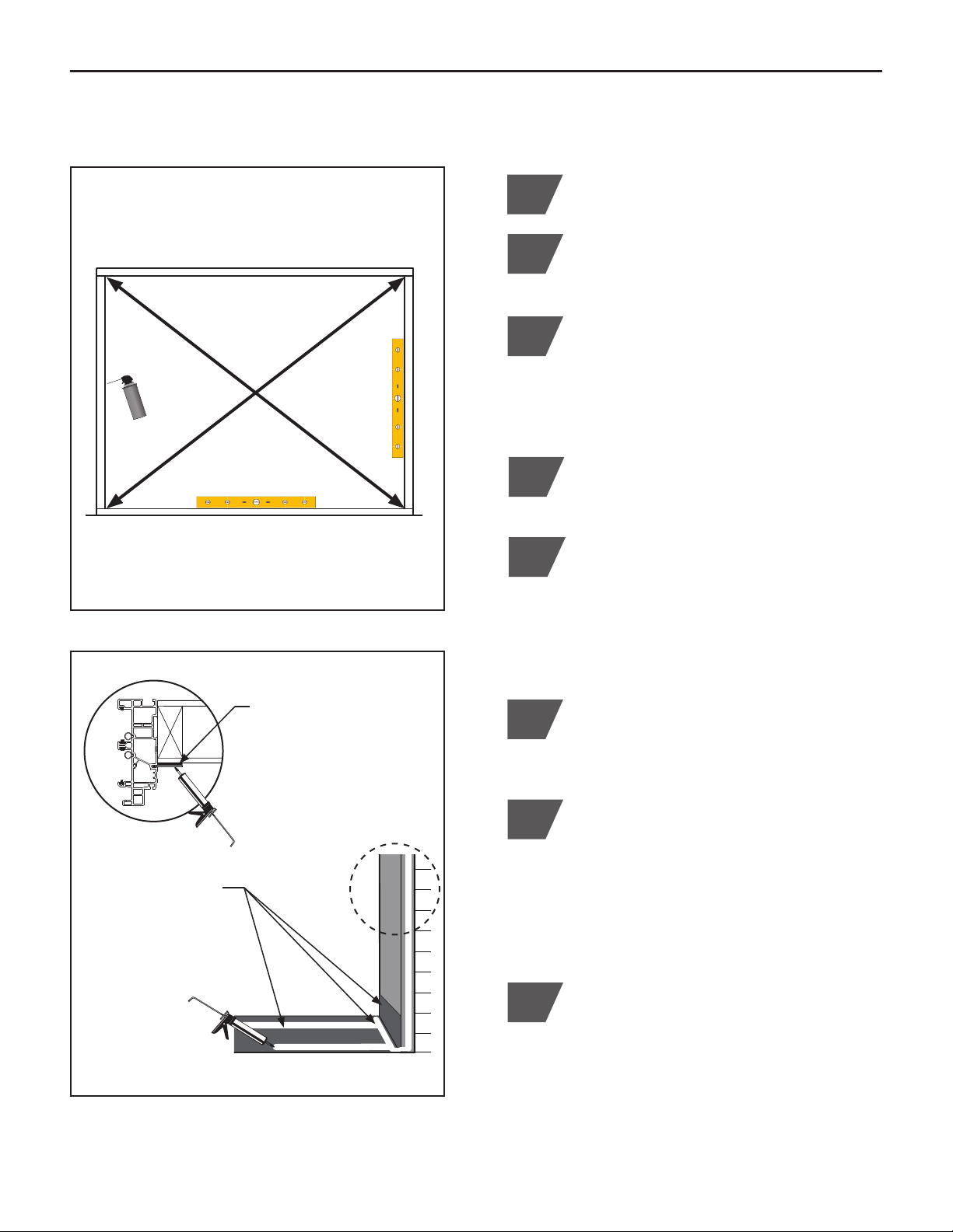
1Clean rough opening of all dirt, debris, and
obstructions.
B. PREPARE OPENING
5Verify opening width and height. Opening
should be large enough to accommodate
patio door with shims and insulation. The
recommended opening size is 1⁄4" - 1⁄2"
greater per side (or 1⁄2" - 1" greater than in
total width) and 1⁄4" - 1⁄2" greater than in total
height.
!
6
(Figure B.1)
(Figure B.2)
Fill all voids found with AAMA approved
low-expanding window insulation foam that
complies with ASTM C 1620. (Figure B.1)
2
Check for level and flat sill. Verify the
structural integrity of the opening to ensure
a proper installation. If sill is not straight
and level, place wood shims between sub-
floor and sill to correct minor leveling and
margin adjustments. (Figure B.1)
3
Opening
7
Exterior View
Fill any and all voids in opening with low
expanding foam
Check sill for level, flat and for proper
structural support
Exterior View
Apply flashing to sill
then apply (2) straight
beads of caulking
along length of sill and
to each corner of sill
as shown
ONLY if frame assembly
is ordered nail fin or
brickmold, apply a bead of
caulking to face of exterior
sheathing to seal against
Apply (2) generous beads of premium
caulking compound in a STRAIGHT LINE,
on top of flashing and along entire length
of rough opening sill. Place first bead of
caulking to the exterior leading edge of sill.
Place second bead towards interior (to bed
flat surface of threshold). Apply caulking in
each corner of sill as shown. (Figure B.2)
Install flashing/pan system to sill area
in accordance with local building codes
and best practices. Replace drip cap if
necessary. (Figure B.2)
If nail fin or brickmold option is used, apply
a bead of caulking to each vertical and
header face of exterior sheathing to seal. To
complete seal, apply bead of caulk from sill
to exterior sheathing, as shown. (Figure B.2)
8
Check opening for square. Measure
diagonally from corner to corner each side
to determine. (Figure B.1)
4
8
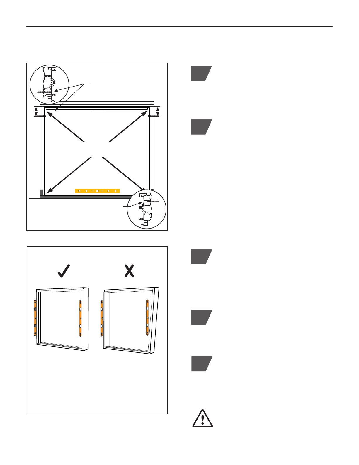
C. INSTALL FRAME
(Figure C.1)
Exterior View
122
1Place assembled patio frame into the
opening, sill first. Center and square frame
in opening. Leave enough space for proper
shimming and insulation.
Install (1) #8 x 3" screw
into top of EXTERIOR jamb
pocket, each side
Install (1) #8" x 3" installation screw (Pack #2)
into the top EXTERIOR jamb pocket of each
fixed sash side, minimum 4" to 6" down from
top corner. Locate screw on score line. DO
NOT over tighten screw causing frame to
pull! (Figure C.1)
NOTE: If using vinyl installation accessory
5940, 5945, or 5956 nail fin, each jamb side
must be secured through the INTERIOR
jamb pocket. Pre-drill a 3⁄8" hole and install
screw into the top of the interior jamb pocket,
minimum 6" down from top corner. Secure to
second vinyl wall of frame. (Figure C.1)
(Figure C.2)
3Check for overall square of patio frame by
measuring diagonally from corner to corner,
each side. Recommended tolerance for the
diagonal measurement is 1⁄8". Adjust top
jamb screws as needed. (Figure C.1)
Level sill if needed. If sill is not straight
and level, it must be shimmed for proper
operation of the patio door.
1214
ONLY if nail fin 5940, 5945, or 5956
is used, install screw into INTERIOR
jamb pocket, second vinyl wall, ea. side
Check sill for level
4"
to
6"
Check frame
for square
CORRECT
Equal vertical
plane alignment
NOT CORRECT
Unequal vertical
plane alignment
Frame Alignment
If frame is bowed, it may be necessary to
shim frame at various locations before
adding installation screws.
5Check plane of the patio frame. Each
vertical jamb side frame should be equal
and parallel to the other. See illustration for
equal and unequal plane. (Figure C.2)
4"
to
6"
9
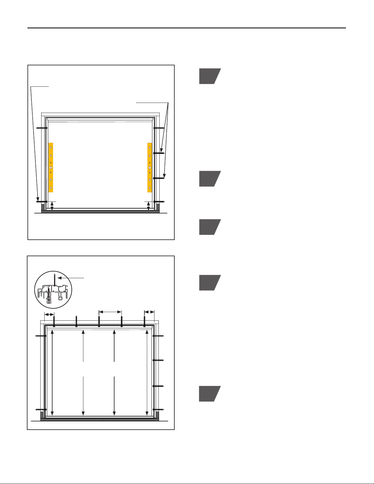
C. INSTALL FRAME (CONTINUED)
(Figure C.3)
6
Exterior View
8
Check each jamb side frame for straight
and parallel to each other. Adjust jamb side
installation screws as necessary for parallel.
Be sure installation screws do not pull vinyl
frame causing frame to bow. Re-check for
overall square and correct plane alignment.
Install (1) #8 x 3" screw into EXTERIOR jamb
pocket 6" from bottom, each side
Install (2) #8 x 3" screws into EXTERIOR fixed
sash jamb side ONLY
Check each jamb side for straight and parallel
9
For header frame, drill a minimum of (5) 3⁄8"
holes equally spaced at 24" maximum through
the first vinyl wall. Wider units will require
more than 5 screws. Place each end screw
hole a minimum of 4" to 6" in from corner.
Install (1) #8 x 3" screw (Pack #2) into each
pre-drilled header screw hole location. DO
NOT over tighten screws causing frame to
pull. (Figure C.4)
NOTE: DO NOT install screw hole plugs at this
time. Plugs will be installed after installation is
fully completed.
Exterior View
(Figure C.4)
Header
Drill and install #8 x 3" screws
in header, 6" in from each
corner and equally spaced
10
Check frame opening height in (4) locations,
each jamb side and center. All (4)
measurements to be equal. Adjust header
installation screws as necessary to achieve
equal measurements. Be sure installation
screws do not pull vinyl frame causing frame
to bow. Header and sill must be parallel for
proper operation of active sash and screen.
(Figure C.4)
Install (1) #8 x 3" installation screw (Pack #2)
into the bottom EXTERIOR jamb pocket of
each jamb side, minimum 4" to 6" up from
the bottom corner. Locate screw on vinyl
score line. DO NOT over tighten screws.
(Figure C.3)
NOTE: If installation accessory 5940,
5945, or 5956 nail fin, secure through the
INTERIOR jamb pocket. Pre-drill a 3⁄8" hole
and install screws as noted above. Secure to
second vinyl wall of frame.
4" to 6"
4" to 6"24" max.
4" to 6"4" to 6"
7
Install (2) #8 x 3" installation screws (Pack #2)
into the EXTERIOR jamb pocket of fixed jamb
side ONLY, equally centered between top and
bottom screws. Locate screw on vinyl score
line. DO NOT over tighten screws. (Fig. C.3)
Frame Only in
Opening
Check frame opening height
in (4) locations for equal

10
Confirm frame is square on the same plane
and not rolled.
12112
C. INSTALL FRAME (CONTINUED)
(Figure C.6)
11 Place shims next to each installation screw
location, each jamb side and header. Be
sure top jamb shims are located 4" to 6"
from top of frame and bottom shims are 4"
to 6" from bottom of frame. Be sure header
shims are located 4" to 6" from each corner. If
spacing between side jamb or header shims
is greater than 12" to 18", additional shims
may be needed to maintain margins and
stabilize frame. Use shims to adjust straight
and parallel as needed. (Figure C.6)
NOTE: To allow for vinyl expansion, DO NOT
place shims at top header, bottom sill, or
header corner locations as shown. Shimming
in these locations will cause frame distortion.
IMPORTANT! CORRECT shimming
application; stack wedge shaped shims
contrasting and plane to plane. See diagram
below. DO NOT use single wedge shims.
This will cause the frame to roll. (Figure C.5)
IMPORTANT! Be careful to NOT over
shim. Improper shimming may roll,
bow, and change margins, jeopardizing
operational performance.
Exterior View
(Figure C.5)
CORRECT
Flat shims or wedge
shims stacked to
create a flat plane will
result straight frame
NOT CORRECT
A wedge shim will
cause frame to roll
resulting in rolled and
bowed frame
SHIMMING APPLICATIONS
Place stacked shims next to each header and
fixed jamb side screw locations
DO NOT place shims at top
and bottom jamb locations, each side
To prevent water infiltration, DO NOT
install screws through sill.
4" to 6" 4" to 6"
11
D. INSTALL FIXED SASHES
4
Section View
(Figure D.1)
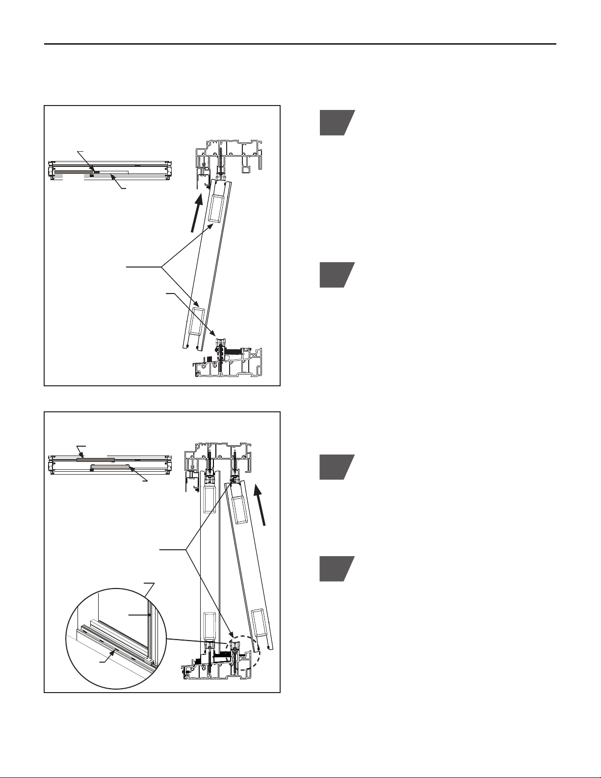
Locate the fixed center sash (sash with an
interlock on each stile). Orient sash with
interlocks facing the interior and weep holes
located to the bottom exterior. From the
exterior active sash side, insert top of center
sash into the outside header track and away
from the anchor blocks. Align bottom of
sash with the sill adapter. Slide sash onto
adapter and over top and bottom anchor
block. Align fixed center sash flush with end
of sill adapter. (Figure D.1)
12
1411 The slide caps located at the top and
bottom of each fixed sash stile is shipped
in the open position. Check to be sure
caps have remained open. In addition,
check to be sure the weather strip within
each interlock has remained in place and
continues to remain in place throughout the
installation.
Interior
Side
Sill Plan View
Active End Side
Insert
Fixed Center Sash
anchor block
From the exterior active
end, insert fixed center
sash before anchor blocks
Open slide caps
Slide sash onto sill adapter
and engage top and bottom
anchor blocks
Section View
(Figure D.2)
Sill Plan View
Fixed End Sash
Insert
Fixed Center Sash
Sill adapter
Insert fixed end sash into inside
header track and before anchor
blocks
Slide sash over top and bottom
anchor blocks to engage
Place (4) shims into bottom of
interior track (Step 3)
Interior
Fixed
Center
Sash
Shims
3Insert (4) self-adhesive shims (Pack #14)
into inside bottom sill track of the fixed end
sash side, evenly spaced and width of the
sash. Refer to detail located in Figure D.2.
Locate the fixed end sash (sash with a
single interlock and no lock prep). From the
interior, orient the fixed end sash with the
single interlock facing outward, positioned
between the center fixed sash interlocks,
and away from anchor blocks. Lift to insert
top of sash into the inside header track then
lowering onto bottom sill roller rail. Slide
sash over top and bottom anchor blocks and
self-adhesives shims, leaving sash open to
complete the following step. (Figure D.2)
Fixed Center Sash
Fixed End Sash

12
5
9Slide top and bottom caps closed on each
fixed sash.
Ea. side of fixed center sash,
insert (1) foam plug into bottom
cavity of stile
8On each side of the fixed center sash, insert
(1) foam plug (Pack #3) into the open TOP
cavity of stile. (Figure D.5)
Caulk ea. side of sill adapter up to
sash and all sides of plug up to sash
On the jamb side of the fixed end sash,
insert (2) foam plugs (Pack #3), side-by-side,
into the open BOTTOM cavity. (Figure D.3)
6Slide fixed end sash tight into jamb pocket,
engaging the fixed center sash interlock.
Check square of frame to sash.
REMINDER: Check to be sure the weather
strip on interlocks have remained in place.
D. INSTALL FIXED SASHES (CONTINUED)
Interior View
(Figure D.3)
On the jamb side of the fixed end sash,
insert (2) foam plugs into bottom open cavity
Slide sash tight into jamb pocket
Exterior View
Exterior View
(Figure D.4)
(Figure D.5)
Bottom
cap
Sill
adapt.
On each side of the fixed center sash,
insert (1) foam plug (Pack #3) into the open
BOTTOM cavity of stile. For each inserted
plug, apply caulking to each side of the sill
adapter up to sash and all sides of the foam
plug up to sash to form a complete seal, as
shown in Detail. (Figure D.4)
NOTE: Check to be sure sash has remained
aligned and flush with end of sill adapter.
7
Ea. side of fixed center sash,
insert (1) foam plug into top
cavity of stile

13
1Check the active sash and fixed center
sash interlock rails to be sure weather strip,
on exterior side, has not slid up or down.
Properly re-seat if needed.
3Note the location of the adjustment screws
located on bottom sash rollers to adjust each
side of active sash as necessary for equal
height, squareness, and margin. Active
sash should fully and evenly enter jamb
pocket. Turn adjustment screw clockwise to
raise sash and counter-clockwise to lower
sash. Unweight sash to assist with upward
adjustment. (Figure E.1)
From interior of home, insert top of the
active sash into the interior header track.
Lift and lower sash onto the sill rolling rail.
(Figure E.1)
2
E. INSTALL END ACTIVE SASH
Section View
Exterior Interior
(Figure E.1)
Insert top of active sash into header track,
lift and lower onto sill rail
Use adjustment screw on bottom sash roller
for height adjustment
D. INSTALL FIXED SASHES (CONTINUED)
Interior View
Install (1) #8 x 1" screw into (1) factory prepped
screw hole at top of each fixed sash
*DO NOT install the remaining (3) screws
in each fixed sash
(Figure D.6)
For each fixed sash, install ONLY (1) #8 x 1"
Phillips pan head screw (Pack #3) into (1)
factory prepped screw hole located at the top
of the fixed sash. This will secure door to top
anchor block. (Figure D.6)
NOTE: DO NOT install the (3) remaining
screws in each fixed sash factory prepped
screw hole locations. This will allow for
adjustment with active sash once installed.
14111
Verify frame opening height in (4) locations,
each side and center sash interlocks, as
previously performed in Section C, Step 10.
Adjust frame header as necessary for equal
measurements. Frame header may need
to be pushed up or pulled down to achieve
equal measurements.
NOTE: THIS STEP IS CRITICAL for the
AccuVent™and screen to operate properly.
14110

14
F. INSTALL REMAINING FIXED SASH SCREWS
12
Interior View
(Figure F.1)
Install (1) #8 x 1" Phillips pan head screw
(Pack #3) into (3) remaining factory prepped
top and bottom screw hole locations of each
fixed sash. (Figure F.1)
Install (1) #8 x 1" Phillips pan head screw into (3)
remaining factory prepped top and bottom screw
hole locations of each fixed sash
1Re-check for equal height measurements
and alignment with active sash. Check for
equal spacing of fixed sashes and closed
active sash. If fixed center sash requires
adjustment, remove screw from Section D,
Step 11.
G. INSTALL MULTI-POINT HANDLE SET
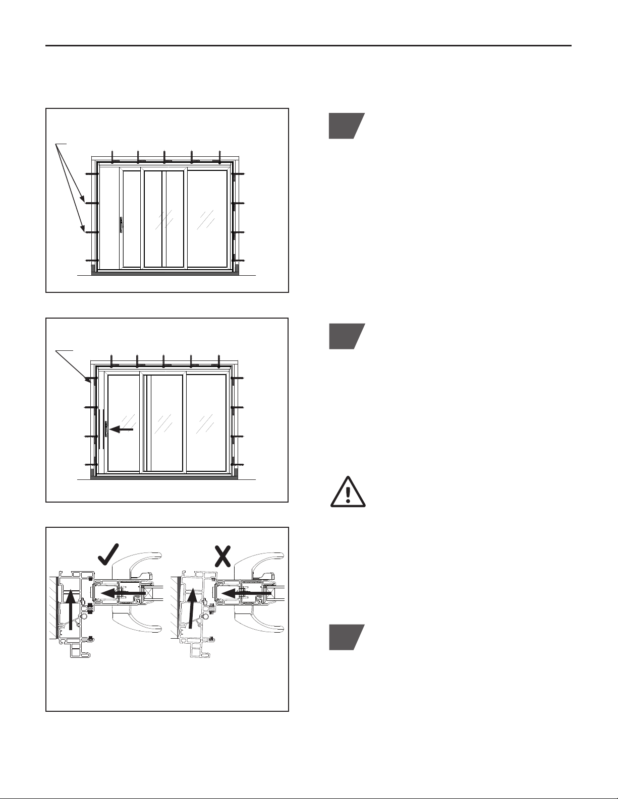
2Position handle set into factory prepped
holes. Align spindle with lock knob on inside
handle. Confirm hand grip curves towards
the glass. (Figure G.1)
3Use (2) #8-32 (included) to install the
exterior and interior handle set assemblies
to the active sash. (Figure G.1)
Install exterior and interior
handle set using
(2) #8-32 Phillips
mounting screws,
included
DO NOT USE a power
screwdriver to install
the handle set kit,
doing so will cause
damage and VOID THE
WARRANTY *DO NOT
OVER TIGHTEN screws
1Fasten handles to each plate using (2)
#10-32 mounting screws provided. Place
gasket in base of exterior plate. (Figure G.1)
(Figure G.1)
Active Sash The primary handle set installation
instructions is located inside hardware
box. Refer to included instructions for
the complete hardware installation.
15
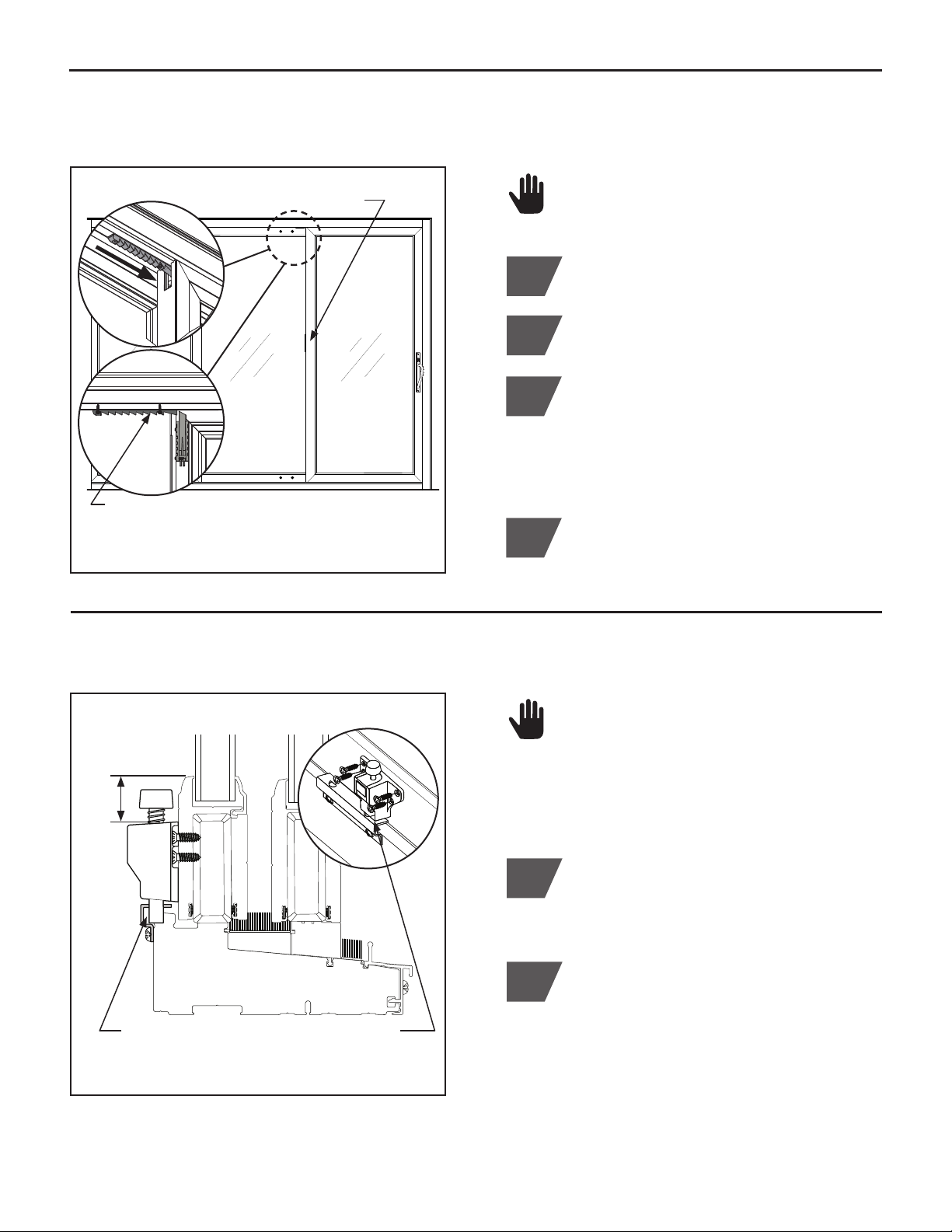
H. INSTALL ACTIVE SASH JAMB SIDE SCREWS AND SHIMS
Slide active sash to almost closed, check
alignment and margin of the sash strike edge
to frame. Shim active sash side frame at
each installation screw to adjust frame as
needed. Be sure top and bottom shims are
4" to 6" away from corners. Additional shims
maybe needed for proper frame alignment.
(Figure H.2) FLAT SHIMS MUST BE
USED. Be careful to NOT over shim
causing frame to roll or bow. (Figure H.3)
2
Re-check sash operation. Sash must slide in
and out of jamb pocket smoothly for proper
operation and lock function. If not, continue
to adjust shims, screws, and the adjustment
screw located on bottom sash rollers to
further align as needed.
3
IMPORTANT! CORRECT sash operation.
If jamb side frame becomes rolled
during installation, the active sash will
conflict with the frame resulting in poor
operation. The jamb side frame must
be straight and parallel to active sash.
Refer to Figure H.3 for an illustration of
proper frame to sash alignment.
(Figure H.3)
1Install (2) #8" x 3" installation screws (Pack
#2) into the EXTERIOR jamb pocket of
the active sash side, locate (2) screws
in center and evenly spaced. DO NOT
tighten screws. Screws can be used for
frame alignment and adjustment in Step 2.
(Figure H.1)
NOTE: If using installation accessory 5940,
5945, or 5956 nail fin, secure through
the INTERIOR jamb pocket. Pre-drill a
3⁄8" hole and install screws into the interior
jamb pocket.
Secure to second vinyl wall of
frame.
CORRECT
Sash slides in and out
of pocket with ease
NOT CORRECT
Sash is difficult to operate,
requires adjustments
Exterior View
Slide sash almost closed to check alignment/margin
Shim to each active sash side screw, use shims to
adjust frame alignment, margin to frame
(Figure H.2)
(Figure H.1)
Exterior View
Install (2) remaining installation screws into active
sash side jamb, centered and evenly spaced
SASH OPERATION
(Figure H.3)
16
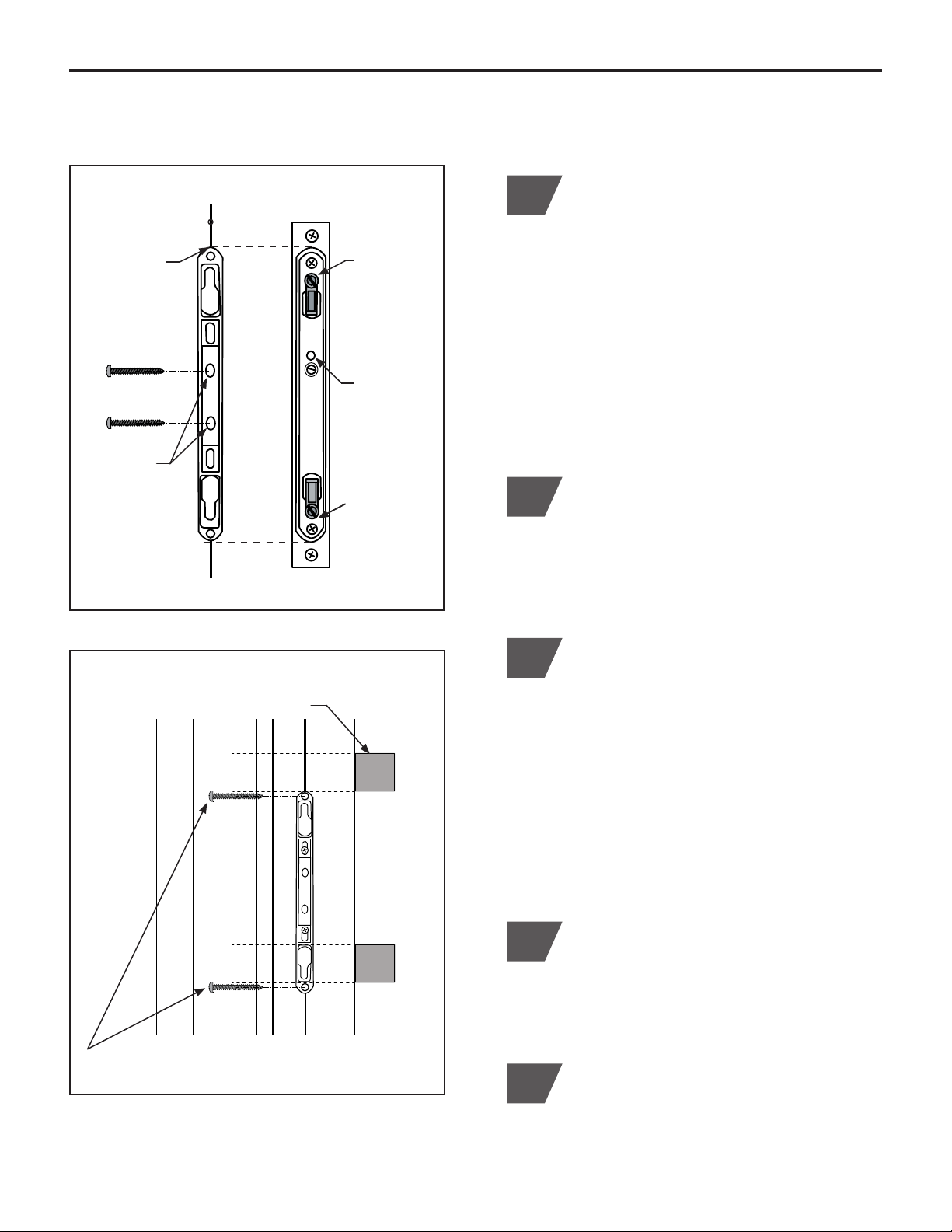
1Slide active sash almost closed, leaving
enough room to align keeper with lock body.
Mark jamb pocket with the location of top
and bottom keeper as aligned with lock
body. (Figure I.1)
Tip: Place (2) strips of double-sided tape
on back of keeper. Locate keeper onto lock
body and lock in place. Close sash tight to
adhere keeper to jamb pocket. Unlock the
lock body and open sash. Install keeper as
directed below.
2
3
Center keeper on jamb pocket score line
between marks made. Install (1) #10 x 1"
screw in each elongated screw hole
locations. This will allow for a slight up and
down adjustment if needed. (Figure I.1)
4
Close active sash, locking and unlocking
handle. If needed, adjust the latch bolt and
keeper positions until sash latches securely
without sash movement or excessive
latching effort. To adjust latch bolt position,
open sash and engage the anti-slam button
to allow the latch bolt to lock. Use a flat
head screwdriver to loosen or tighten latch
bolt as needed. Test function of the lock.
Repeat step if lock is still too tight or too
loose. (Figure I.1)
After final adjustments are completed,
install (1) #8 x 3" screw (Pack #2) at top
and bottom of the keeper to secure in place.
(Figure I.2)
(Figure I.1)
Vinyl score line
Align keeper
with lock body
and mark top
and bottom
location
Latch bolt
adjustment
Anti-slam
button
Latch bolt
adjustment
Keeper Lock Body
I. INSTALL KEEPER
(Figure I.2)
Keeper in Jamb Pocket
After adjusted, install (1) #8 x 3" screw in the
top and bottom keeper screw hole location
To secure,
install (1) #10 x
1" screw in each
elongated screw
hole location
5Place shims immediately above each top
and bottom keeper screw location.
(Figure I.2)
Place shims above top and bottom
screw location
Interior
Side
Exterior
Side
17
J. INSTALL HEAD WEATHER STRIP BLOCKS & INSECT STOPS
1Locate weather strip blocks directly above
each interlock. With active door open, insert
both blocks into center channel of frame
header. Slide first block past active side
interlock using the second block. Use a thin
long screwdriver to push second block into
position over active sash side interlock. Close
active sash. Slide first block into position over
fixed end sash interlock.
(Figure J.1)
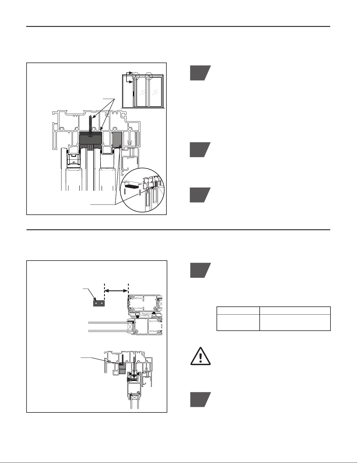
K. INSTALL SASH STOP
1Place sash stopper (Pack #5) on the active
sash header track, behind active sash.
Locate the sash stopper per the appropriate
dimension provided in chart below and per
the illustration in (Figure K.1).
Sash Type Dimension ‘A’
Without Blinds 23⁄4" from edge of fixed sash
With Blinds 4" from edge of fixed sash
IMPORTANT! To avoid a pinch hazard
between exterior handle set and fixed
sash, do not allow less than the above
dimensions.
2Install sash stopper with (2) #8 x 11⁄4" Phillips
pan head screws (Pack #5).
Install (2) #8 x 11⁄4"
Phillips pan head
screws
(Figure K.1)
Sash Plan View
Dim.
'A'
Header Section
Place sash stopper
on the active sash
header track, locate
at the distance
provided in chart
2Secure each head weather strip block using
(2) #8 x 11⁄4" Phillips pan head screws (Pack
#4). For active sash side, close sash to
access the opposite screw hole. DO NOT
over tighten screws. (Figure J.1)
3Insert (1) foam plug (Pack #3) in the open
cavity between the fixed center sash and
screen track, each side of sash and as shown.
Foam plug must align with edge of fixed center
sash, as shown in Detail. (Figure J.1)
Head Weather Strip Block Section
End
Active
Sash
Fixed
Center
Sash
Insert (1) foam stop (plug) in
open cavity, each side
Locate weather strip blocks above
each interlock, secure using (2)
#8 x 11⁄4" screws each block
Sash Stop Location
Fixed End
Fixed Center
18
1Close active sash and lock handle.
2Flip AccuVent lever down into locked
position. (Figure L.1)
3Locate the AccuVent bolt plate (AccuVent
Bolt Plate Kit) on the active sash header
track. Slide plate into the stile opening of the
active sash, next to the AccuVent bolt, as
shown in Figure L.1. Provide a 1⁄8" clearance
between bolt plate and bolt. (Figure L.1)
4Pre-drill a 3⁄32" or 7⁄64" hole and install (2)
#8 x 1" screws (AccuVent Bolt Plate Kit).
DO NOT over-tighten screws. (Figure L.1)
L. INSTALL ACCUVENT™VENTING SYSTEM BOLT PLATE
(Figure L.1)
Interior View
Flip AccuVent lever down
Locate AccuVent bolt plate, slide plate into
opening of active sash, leave 1⁄8" clearance,
install with (2) #8 x 1" screws
AccuVent is a standard feature on all
Endure™and an optional feature on all
Aspect™.
M. INSTALL FOOT LOCK
Foot lock is a standard feature on all
Aspect™ and an optional feature on all
Endure™.
Foot lock keeper is factory mounted.
1Close active sash and lock handle.
Align foot lock (Pack #6) over the first hole
of keeper, closest to the latch side. Locate
and install foot lock body a minimum of 15⁄16"
below top of sash rail, as shown. Check to
be sure bolt will engage keeper. Secure to
sash using (4) #8 x 3⁄4" Phillips oval head
screws (Pack #6). (Figure M.1)
2
(Figure M.1)
Foot Lock Section View
15⁄16"
Latch
Side
Align foot lock over first hole of keeper,
locate a minimum of 15⁄16" below top of sash rail,
secure using (4) #8 x 3⁄4" screws
Top of sash rail

19
N. INSERT SCREEN
3
Lift screen into the top screen track
assembly and between wheel brackets.
Place screen with the weather strip to the
interior side. (Figure N.2)
4
Lift and position bottom of screen onto
screen glide rail. (Figure N.2)
5
Insert the left and right wheel bracket tabs
into groove located at the top of screen
frame. (Figure N.3)
Install each wheel bracket using a #2
Phillips head screwdriver to install (1)
#6-32 x 7⁄8" Phillips flat head screw
(Pack #10). (Figure N.3)
NOTE: DO NOT use excessive torque on
the bracket screws.
1Insert Left and Right screen wheel brackets
into the inner track of the top screen track
assembly (Pack #10). Brackets are labeled
and identified by outside looking in. Insert
rollers into the open space located at the
ends of the inner screen track and the jamb.
BE SURE each wheel bracket is positioned
correctly. (Figure N.1)
Insert Left and Right
wheel brackets into
end of inner track
2
(Figure N.1)
(Figure N.2)
(Figure N.3)
Screen Track Section
Outer screen cover
Inner screen track
Section View
Lift screen into the
top of track, between
wheel brackets
*Be sure screen
weather strip is to the
interior side
Position bottom of
screen onto glide rail
Screen Track Section
Insert wheel bracket tab
into screen groove
Install each wheel bracket
with (1) #6 x 7⁄8" screw
This manual suits for next models
1
Table of contents


