Elite Industries EL-907 User manual
PLEASE DO NOT RETURN UNIT TO STORE
FOR PARTS & CUSTOMER SERVICE PLEASE CALL 1-800-ELITE-48
CUSTOMER SERVICE HOURS EASTERN TIME 8:45 AM - 4:45 PM M-F
Thank you for purchasing this Elite product. You will need the following tools:
Phillips Head Screw Driver • Straight Blade Screw Driver • Rubber Padded Hammer or Mallet
F
8
Plastic Glass
Cushion
G
12
Self-Adhesive
Spacer Disk for
under Glass
H
4
2" Screw for Bottom
Support Rails
J
4
11/16" Screw for
Wire Management
A
8
Connecting
Bolts
B
8
Camlocks
C
8
Wooden
Dowels
D
1
Hex Key
Tool
E
4
1-3/16" Bolts for
Metal Frames
Hardware for unit assembly
1
11
8
9
10
10
4
5
3
3
2
6
7
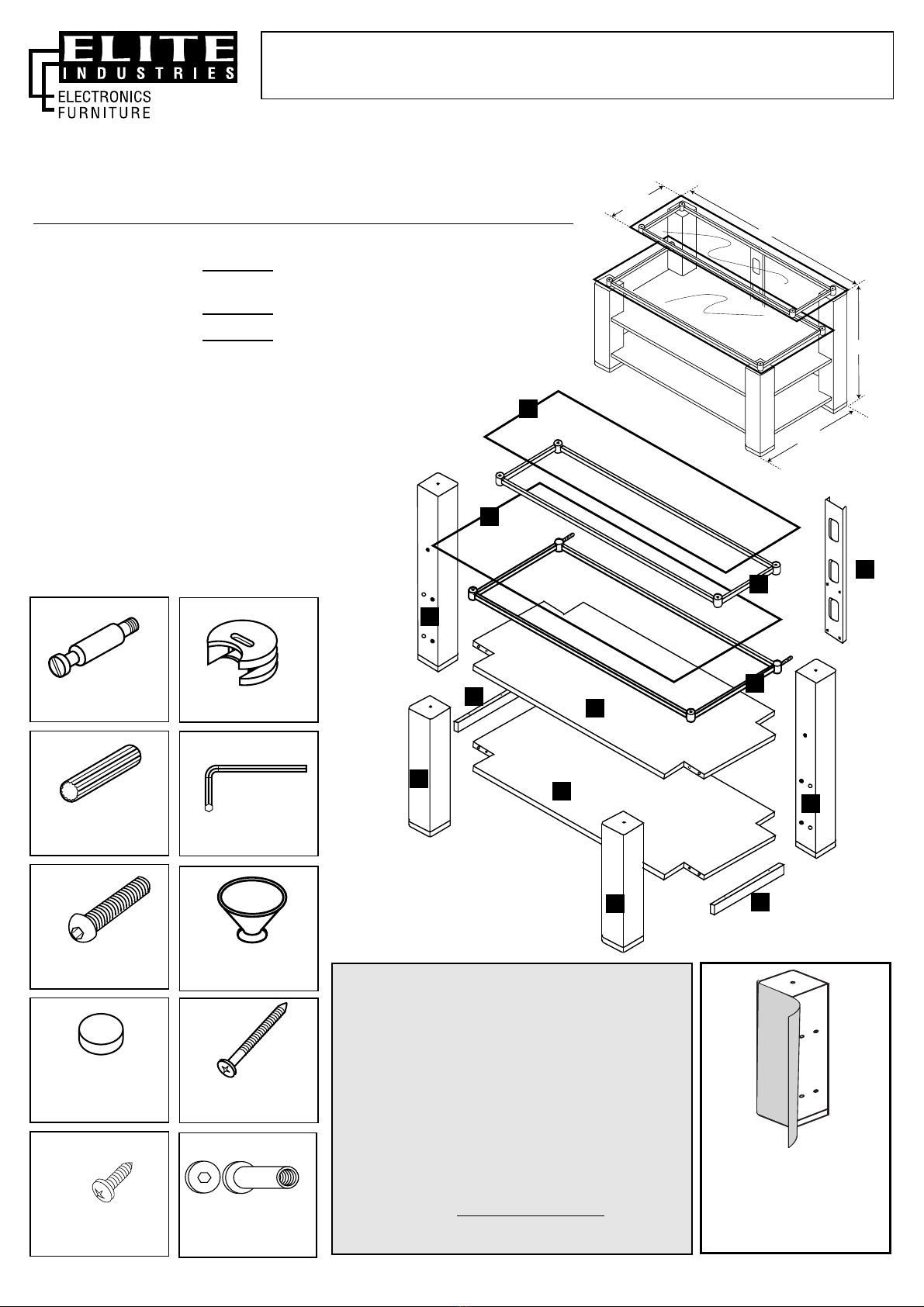
ASSEMBLY INSTRUCTIONS
45" WIDE TV STAND, AUDIO/VIDEO COMBINATION UNIT
DESIGNED FOR PLASMA, LCD, DLP & THIN FLAT-PANEL TV’S
OVERALL DIMENSIONS: 26" H x 45" W x 21 3/4"D
EL-907: Wenge Melamine
(A rich, deep brown-black, wood-grain finish)
EL-947: High Gloss Black Lacquer
EL-957: Gray Melamine
14"
45"
26"
21 3/4"
IMPORTANT NOTES & CAUTIONS/WARNINGS
• Carefully read and follow these instructions for assembly.
• Please handle parts carefully, some parts may be heavy and can
have sharp edges – we recommend possibly using cloth protective
gloves for extra protection.
• To protect the unit and your flooring surface we recommend working
on a padded or carpeted area, you may also use the open box the
unit came in for this purpose.
• For proper construction & integrity/assembly and for TV weight
support and safety, all connections need to be sufficiently tight.
However, do not over-tighten connections to the point of stripping
screw threadings. Parts are designed to fit together tightly, however,
avoid excessive force but rather align & fit panels together methodi-
cally and with patience.
• For some heavy or large units, it may be recommended for 2 people
to work together on this assembly.
• Please read additional important safety information at the end of
this instruction manual.
• We urge you to keep this manual with your unit for future reference.
BLACK
K
2
11/16" Threaded
Bushings for Large
Metal Frame
CHROME
CHROME
PARTS
1. Glass Top Panel Surface (14" x 45")
2. Glass Shelf
3. Wooden Shelf (2 identical)
4. Small Metal Frame for Glass Top Panel Surface
5. Large Metal Frame for Glass Shelf
6. Front Left Leg
7. Front Right Leg
8. Back Left Leg
9. Back Right Leg
10. Support Rail (2 identical)
11. Wire Management Channel
BLACK
474534 Page 1/4 7.10.06
SPECIAL NOTE for EL-947
Legs have a foil wrapping to
protect the High Gloss Finish.
Please remove this wrapping
before proceeding with
Step #1, Leg Preparation.
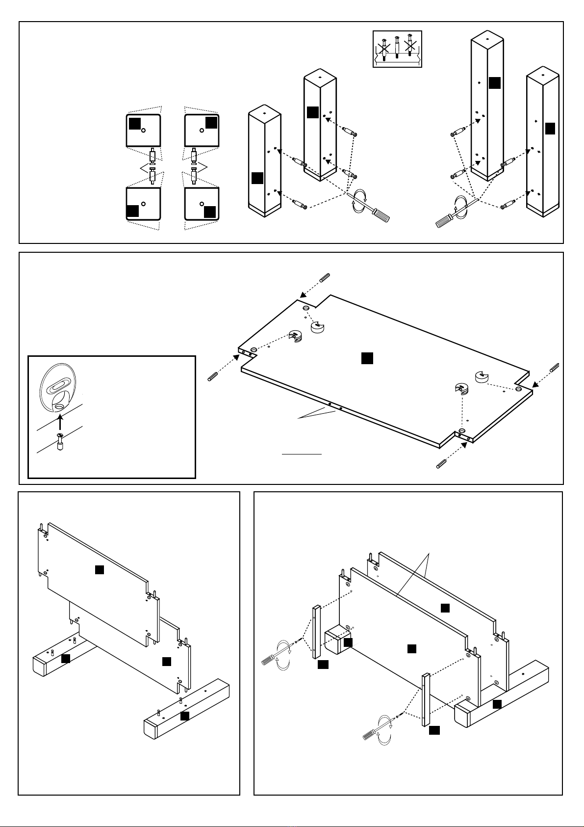
1FRONT & BACK LEG PREPARATION
2 WOODEN SHELF PREPARATION
3
AA
C
C
C
C
B
B
B
B
7
3
8
6
9
(Underside)
Holes for Wire
Management
Channel on
Back Edge
Screw Connecting Bolts (A) into each Leg as shown.
Note that each leg has 2 square corners and 2 rounded
corners. The rounded corners will always face out and
the square cornered edge has the holes to receive the
Wooden Dowels
(C) and holes
with factory
installed thread-
ed bushings to
insert the
Connecting
Bolts (A).
SPECIAL NOTE
In all steps involving camlocks,
please note the correct posi-
tion of the camlock in the illus-
tration at the left. Check all
camlocks before aligning and
joining pieces together.
IMPORTANT: Throughout
assembly of the unit, cam-
locks must be inserted with
the openings facing the
nearest unfinished edge and screwdriver
slot parallel to unfinished edge.
3
3
9
9
8
Place Wooden Shelf (3) on flat padded surface
with underside facing up. Insert 4 Camlocks
(B) and 4 Wooden Dowels (C) as shown.
Repeat procedure for second Wooden Shelf.
NOTE: Back Edges have holes for attaching
Wire Management Channel (11).
WHEN INSERTING
CONNECTING BOLTS
DO NOT OVERTIGHTEN
Place Back Legs (8 & 9)
on flat padded surface
with Connecting Bolts (A)
face up. Align holes and
Dowels (C) of Wooden Shelves
with Back Legs (8 & 9). Join pieces together.
Turn Camlocks (B) 180° clockwise to lock
pieces together.
(Underside)
(Underside)
3
(Underside)
3
(Underside)
4ADD BOTTOM SUPPORT RAILS
CONNECT BACK LEGS
TO WOODEN SHELVES
Using Wooden
Screws (H),
and a Philips Head
Screwdriver
attach Support Rails
(10) as shown.
Do not overtighten
screws.
8
10
10
H
H
SQUARE
CORNERS
CONNECTING
BOLTS
“A”
CONNECTING
BOLTS
“A”
ROUNDED
CORNERS
ROUNDED
CORNERS
89
7
6
FRONT EDGE
FRONT EDGE
FRONT EDGE
FRONT EDGES
Make sure front
edges of both
Wooden Shelves (3)
face up
474534 Page 2/4 7.10.06

9
6
8
7
3
3
ALIGN
CAMLOCK
WITH
CONNECTING
BOLT
JOIN
PIECES
TOGETHER
TURN
CAMLOCKS
180° CLOCKWISE
USING A
FLATHEAD
SCREWDRIVER
CAMLOCK/CONNECTING BOLT
PROCEDURE
(Underside)
(Under-
side)
67
ATTACH LARGE METAL FRAME FOR GLASS SHELF ATTACH SMALL METAL FRAME
FOR GLASS TOP PANEL
8ATTACH WIRE MANAGEMENT CHANNEL
Attach Wire
Management
Channel (11) to
Wooden
Shelves (3) at
Back Edge
using a
Phillips Head
Screwdriver
and 4
Screws (J).
5ATTACH FRONT LEGS
LOCK ALL CAMLOCKS
Align Connecting
Bolts (A) of Front Right
and Left Legs with
appropriate holes of
Wooden Shelves. Join
pieces together. Turn
Camlocks (B) 180°
clockwise to lock pieces
together. Be sure to
lock all 4 Camlocks for
each shelf.
Frame Bolt
“E” goes all
the way
through
Small Metal
Frame at
corners
Frame Bolt
“E” goes all
the way
through
Large Metal
Frame at
corners
Place unit in upright position. Align threaded posts of
Large Metal Frame (5) with corresponding holes on 2
Back Legs (8 & 9). Insert threaded posts.
Using 2 Bolts (E),
attach front of Large
Metal Frame (5) to
Front Legs (6 & 7).
Tighten Bolts (E) completely.
Now tighten the Threaded
Bushings (K) at the back of
each leg.
Tighten Threaded Bushings
(K) completely.
Using 2 Bolts (E), attach Small Metal Frame (4) to
Back Legs (8 & 9) as shown. Tighten completely
using Hex Key Tool (D).
E
J
E
D
D
D
K
K
5
5
11
6
7
8
9
8
9
4
Insert
Threaded
Bushings (K)
into back of
legs but do
not tighten.
474534 Page 3/4 7.10.06

Congratulations and enjoy your new ELITE product!
To clean your unit, apply window cleaner with soft tissue. This will also eliminate slight surface abrasions or scratches
that may have occurred in shipping or handling.
Distributed by: Elite Industries, 77 Gould Street • Bayonne, NJ 07002, Tel.: 201-436-1120 • Fax: 201-436-6960
Elite Industries ensures complete satisfaction with this product. In the event of missing or damaged parts call toll free, Customer service
hours: 8:45-4:45, Monday-Friday, EST., 1-800 ELITE-48
IMPORTANT SAFETY PRECAUTIONS
Please carefully read & follow these important safety information notes for proper use of the furniture you have just assembled.
They are designed to avoid unsafe conditions that can result in property damage, bodily injury or death. We therefore urge strict
adherence to the following basic principals:
• Install this unit on a flat & level surface only.
• Avoid placing unit in direct sunlight or near heating source. We recommend not placing unit directly against wall but rather leav-
ing a narrow space between unit and wall for proper ventilation of your A/V equipment.
• Do not exceed the above recommended weight loading limits as this can result in sagging or structural failure of the supporting
panel leading to unsafe conditions.
• TV screen sizes are measured diagonally, therefore, base foot-print size for specific TV’s can not be determined by screen size
as they vary from manufacturer to manufacturer. Rather you will need to measure the TV’s base foot print and compare it to the
glass top panel surface size of your furniture as listed in this manual.
• Make sure to place TV within the surface area of the top panel, a bit inward from the front edge and centered. Never use with
a TV that is too large. The TV base foot print surface must be able to sit completely on the top panel surface.
• When choosing locations for stacking A/V components on shelves, make sure to place the heaviest A/V equipment on the low-
est possible shelves/bottom panels first.
• Children should never be allowed to climb on or play with this furniture or/and the TV. This can result in an unsafe situa-
tion which may lead to the TV and/or the furniture itself to become unsteady, slip, tip or fall over. Avoid using higher shelves or
the top surface of the TV for objects that may tempt children to reach and climb. Such items can include toys, food, as well as
remote controls, etc. Proper supervision and common sense is always required.
• Glass surfaces and doors are “Tempered.” This is a special process for achieving strength and safety. Although durable & solid
we recommend avoiding bumping into glass with force or dropping or chipping edges etc. Special caution should be given to
glass corners, both, for protection of glass as well as most importantly to avoid the possibility of injuries resulting from strong
impacts against corners especially with children. Doors should be opened & closed gently. (Tempered glass is designed to
shatter upon very strong impact and rather than producing sharp knife-like dangerous edges, it turns instead into small pebble-
like pieces.)
• Moving the unit: Do not drag unit when moving, especially not on a carpeted surface or on a rug. It is always recommended
instead to lift unit from both ends with a friend’s help. For the sake of safety and to avoid damages, we recommend you
remove the TV and all A/V components prior to moving this stand. It is a good idea to remove the glass panel surfaces as well.
If this is not possible please use much caution and good judgment and seek help to ensure stability and safety as the stand is
being moved. Make sure afterwards to properly re-adjust glass top and all equipment, centered and stable as originally
instructed above.
IMPORTANT NOTICE
The glass top panel surface (Part #1) is
designed to be used with
TV's and other A/V equipment
NOT weighing more than 220 lbs.
The loading weight needs to be evenly
distributed across top panel and for optimum
stability, place TV in a center position on
glass top, not unbalanced to the side
against edge for example.
Avoid concentration of heavy weight loading,
(over 110 lbs.), on a small surface area of less
than 311/2" in width.
Also: Note dimensions for Glass Top Panel
Surface as listed at the beginning of this
manual and read the following
"Important Safety Precautions".
Part #2, Glass Shelf, is designed to be used
with A/V components
NOT weighing more than 110 lbs.
Part #3, Wooden Shelves, are designed
to be used with A/V components
NOT weighing more than 66 lbs. per shelf.
HOWEVER, for the total unit loading
capacity, DO NOT exceed a total of 440 lbs.
9ADD GLASS CUSHIONS AND SPACER DISKS
CENTER GLASS TOP AND GLASS SHELF
Insert 8 Glass Cushions (F) into all holes of both Metal Frames.
Attach 6 self-adhesive Spacer Disks (G) to each Metal Frame as
shown. Place unit where desired and carefully lay Glass Top and
Glass Shelf (1 & 2) on unit, centering them on Glass Cushions.
Make sure Glass
Top (1) and Glass
Shelf (2) are
centered on
Glass Cushions
(F) with equal
overhang at all
four corners.
1
2
4
5
F
FG
G
474534 Page 4/4 7.10.06
This manual suits for next models
2
Other Elite Industries Indoor Furnishing manuals

Elite Industries
Elite Industries EL-906 User manual

Elite Industries
Elite Industries EL-9973 User manual

Elite Industries
Elite Industries EL-250 User manual

Elite Industries
Elite Industries EL149 S User manual

Elite Industries
Elite Industries EL-785 User manual

Elite Industries
Elite Industries CREDENZA EL-1195 User manual

Elite Industries
Elite Industries EL-469 User manual

Elite Industries
Elite Industries EL-905 User manual

Elite Industries
Elite Industries EL-147N User manual

Elite Industries
Elite Industries EL-221 User manual


