Proview CF3213-XA User manual
□ 系 統 文 件 ▓ 第一類支援文件 □ 第二類支援文件
REVISION: A1
(文件版本)
PAGE 1 OF 46
REVISION
T
ATUS
(內文版本)
SUBJECT:
(主旨) CF3213-XA
MODEL NO:
CF3213-XA
(機種)
DOC.NO:
(文件編碼)
EFFECTIVE DATE:
(生效日期)
發行一日後生效 PAGE REV.
(變更記錄)
變更次數 變更內容
COPY TO
收文單位
All CONTENTS
(全文)
1
2
3
4
5
6
7
8
9
10
11
12
13
14
15
16
17
18
19
20
21
…
45
46
A1
A1
A1
A1
A1
A1
A1
A1
A1
A1
A1
A1
A1
A1
A1
A1
A1
A1
A1
A1
A1
A1
A1
A1
APPROVED BY/核准
REVIEWED BY/審核
PREPARED BY/擬稿
CONCURRED BY/會簽

1
TABLE OF CONTENTS
1. Precautions and Safety Notices ································· 2
2. Specification ················································· 3
3. Front Panel Function Control Description ························· 8
4. Adjusting Procedure ········································· 13
5. Trouble Shooting Flow Chart ·································· 16
6. Exploded Diagram and Spare Parts List ·························· 19
7. Block Diagrams ·············································20
8. Schematic Diagrams ···························································· 21
9. PCB Layout Diagrams ·········································42

2
1. Precautions and Safety Notices
Prior to using this service manual,please ensure that you have carefully followed all the procedures outlined in
the user's manual for this product.
(1) Read all of these instructions.
(2) Save these instructions.
(3) Follow all warnings and instructions a marked on the product.
(4) Unplug this product from the wall outlet before cleaning.Do not use liquid cleaners or aerosol cleaners, use a
damp cloth for cleaning.
(5) Do not use this product near water.
(6) Do not place this product on an unstable cart,stand or tablle.The product may fall,causing serious
damage to the product.
(7) Do not tear up the EMI label, if the label has been destroyed,that must to past same size label on the same
position.
(8) Slots and openings in the cabinet and the back or bottom are provided for ventilation,to ensure reliable
operation of the product and to protect it from overheating,those openings must not be blocked or
covered.The openings should never be blocked by placing the product on a bed,sofa, rug, or other similar
surface.This product should not be placed in a built-in installation less proper ventilation is provided.
(9) This products should be operated from the type of power source indicated on the marketin label. If you are
not sure of the type of power available, consult your dealer or local power company
(10) This product is equipped with a 3-wire grounding type plug,a plug having a third (grounding) pin. This plug
will only fit into a grounding-type power outlet. This is a safety feature, if you are unable to insert the plug
into the outlet, contact your electrician to replace your obsolete outlet. Do not defeat the purpose of the
grounding-type plug.
(11) Pay attention to the code which connects with apheliotropism board of inside panel.and don’t hook it.
(12) Do not allow anything to rest on the power cord.Do not locate this product where persons will walk on the
cord.
(13) If an extension cord is used with this product,make sure that the total of the ampere ratings on the product
plugged into the extension cord to the waplugged into outlet does not exceed 15 ampere.
(14) Never push objects of any kind into this product through cabinet slots as they may touch dangerous voltage
points or short out parts that could result in a risk of fire or electric shock.Never spill liquid of any kind on the
product.
(15) Do not attempt to service this product yourself,as opening or removing covers may expose you to
dangerous voltage points or other risks.Refer all servicing to service personnel.
(16) Unplug this product from the wall outlet and refer servicing to qualified service personnel under the following
conditions :
a. When the power cord or plug is damaged or frayed.
b. If liquid has been spilled into the product.
c. If the product has been exposed to rain or water.
d. If the product does not operate normally,when the operating instructions are followed.Adjust only those
controls that are covered by the operating instructions since improper adjustment of other controls may
result in damage and will often require extension work by a qualified technician to restore the product to
normal operation.
e. If the product has been dropped or the cabinet has been damaged.
f. If the product exhibits a distinct change in performance,indicating a need for service.
3
2. Specification
CF321 panel specification:
Item Specifications
Panel Name CMO
Panel Model No. V320B1-L04
Display pixels 1366 (H) x 768 (V) pixels ( 1 pixel = 1 RGB cells )
Display Area 714.96mm (H) x 404.6mm (V)
Pixel Pitch 0.1730mm (H) x 0.5190mm (V)
Display Colors 16.7M
Pixel Arrangement R+G+B vertical stripe
Brightness 550cd/m2 typical
Contrast Ratio 1200:1 typical at CR ≧10
Viewing Angle 176 (H)/ 176(V) Typical
Color Chromaticity (CIE) White: x = 0.285 , y = 0.293
Frame Rate 50/60Hz
Response Time 6.5ms typical
Surface Treatment Hard Coating:3H, Haze:40%
Anti-reflective coating<2% reflecting
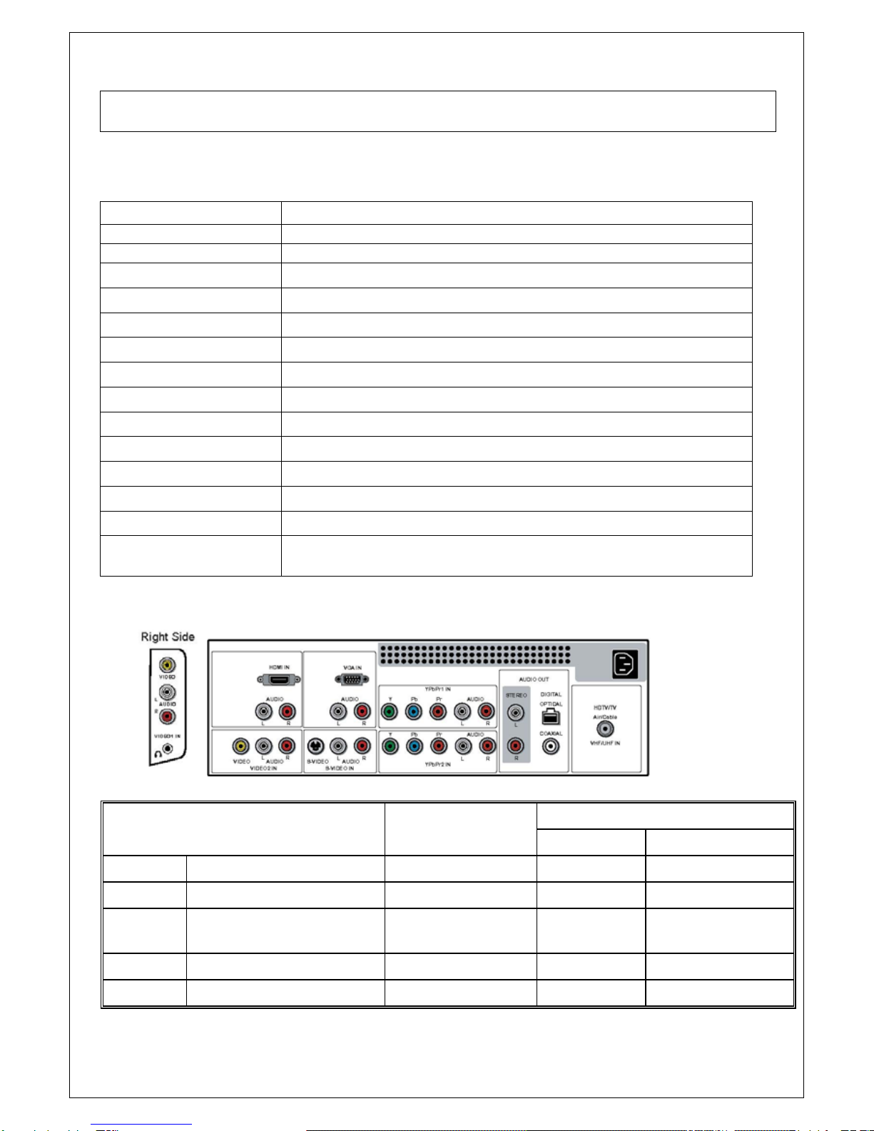
INPUT Source :
Connector typesInputs &
Outputs Signals Video Format
OSD
TV Analog TV NTSC F Type TV (CABLE/AIR)
DTV Digital TV 8VSB F Type HDTV (CABLE/AIR)
VIDEO1 Video + L/R Audio +
Earphone Out
CVBS RCA VIDEO1 (SIDE)
VIDEO2 Video + L/R Audio CVBS RCA VIDEO2 (REAR)
S-VIDEO S-VIDEO+ L/R Audio Y/C Mini Din 4 Pin VIDEO3 (S-VIDEO)

4
YPbPr1 Component
(Y, Pb/Cb, Pr/Cr)
+ L/R Audio
480i, 480p, 720p,
1080i RCA VIDEO4 (YPbPr1)
YPbPr2
Component
(Y, Pb/Cb, Pr/Cr)
+ L/R Audio
480i, 480p, 720p,
1080i RCA VIDEO5 (YPbPr2)
HDMI HDMI Digital RGB +Digital
Audio
HDMI 19 Pin
VIDEO6 (HDMI)
VGA VGA+ L/R Earphone Analog RGB D-SUB 15 Pin COMPUTER (VGA)
L/R Audio RCA STEREO
AUDIO
OUT
Digital Optical/COAXIAL TOSLINK/RCA
DIGITAL
AC IN AC Power IN AC 100~240V YC14 AC IN
Note:
A. HMDI connector is a type A receptacle for video/audio mode.
1. TMDS Data 2+ 9. TMDS Data 0- 17. CEC/GND
2. TMDS Data 2 shield 10. Clock + 18. +5V Power
3. TMDS Data 2- 11. Clock shield 19. Hot Plug Detect
4. TMDS Data 1+ 12. Clock -
5. TMDS Data 1 shield 13. CEC
6. TMDS Data 1- 14. NC
7. TMDS Data 0+ 15. DDC CLK
8. TMDS Data 0 shield 16. DDC DATA
B. D-Sub Connector IN. (This function also can provides to HDTV.)
D-Sub type Connector pin assignment
1. Red Video 6. Red Ground 11. GND
2. Green Video 7. Green Ground 12. SDA For DDC1/2B

5
3. Blue Video 8. Blue Ground 13. H-sync.
4. GND 9. +5V from PC 14. V-sync.
5. Vdd from PC for DDC 10. Sync. GND 15. SCL For DDC1/2B
C.RCA jacks are all female type.
D.Mini DIN CNC 4 Pins (SCN570S3NS00000) for S-video, the pin assignment is
described as below:
HDMI
Format DVI 1.0
Level/Impedance 0.5~3.0Vp-p/100 Ohm (Differential),50 Ohm (Single ending)
TMDS Mode Single Link
Frequency Fh = 31~60 kHz
Fv = 56~76 Hz
Maximum Pixel Clock 135 MHz
DDC 1/2B Compliant with Revision 1.0
Connector HDMI x 1
Analog HD15 PC Signal (RGB)
Format R, G, B Analog
Level/Impedance 0.7Vp-p / 75
DDC 1/2B Compliant with Revision 1.0
Sync H/V separate
3V TTL level / 1k
Frequency Fh = 31~60 kHz
Fv = 56~76 Hz
Maximum Pixel Clock 135 Mhz
Connector Mini D-Sub 15 pin (female) x 1
Video (Composite) CVBS Signal
Format NTSC, 4.43NTSC, PAL_M, PAL(B,G,H,D,N), SECAM
Level / Impedance 1.0Vp-p / 75
S-Video (Y/C) Signal
1: Ground
2: Ground
3: Y
4: C
6
Format Y, C
Level / Impedance Y: 1.0Vp-p / 75
C: ±286 mV/ 75
Analog HD15 Video Signal (YPbPr/YCbCr)
Format Y, Pb, Pr or Y, Cb, Cr
Level / Impedance Y: 1.0Vp-p / 75
Pb/Cb, Pr/Cr: 0.7 ±0.035Vp-p / 75
HDMI Timing
STANDARD RESOLUTION
V FREQ
Hz H FREQ
kHz CLK
MHz
ATSC, 480i 720x480 60 15.7 27
ATSC, 480p 720x480 60 31.5 27
ATSC, 1080i 1920x1080 60 33.7 74.2
ATSC, 720p 1280x720 60 45.0 74.2
ATSC, 576i 720x576 50 15.6 27
RGB PC Timing
STANDARD RESOLUTION
V FREQ
Hz H FREQ
kHz CLK
MHz
VGA 640x480 60 31.47 25.16
VGA 640x480 75 37.5 31.5
SVGA 800x600 60 37.88 40
SVGA 800x600 75 46.9 49.5
XGA 1024x768 60 48.36 65.0
XGA 1024x768 75 60.02 78.75
SXGA 1280x1024 60 64 108
SXGA 1280x1024 75 80 135
MAC 640x480 67 35 30.24
Non-VESA 720x400 70 31.5 28
Video & S-Video AV Timing
STANDARD RESOLUTION
V FREQ
Hz H FREQ
kHz CLK
MHz
NTSC 525 60 15.734 12.65
PAL(B,G,H,D,I) 625 50 15.625 14.50
SECAM 625 50 15.625 14.50
4.43NTSC 525 60 15.734 12.65
PAL-M 525 60 15.734 12.65
PAL-N 625 50 15.625 14.50
HDTV/Component AV Timing
SDTV 525i 720x525 60 15.735 27
SDTV 625i 720x625 50 15.625 27
SDTV 480p 720x480 60 31.5 27
HDTV 720p 1280x720 60 50.0 74.2

7
HDTV 1080i 1920x1080 60 33.7 74.2
Power Source AC100 – 240 V, 60/50 Hz
Sound Output 10W X2, 8 Ohm.
Signal Connector Pin Assignment
Pin Assignment Pin Assignment Pin
A
ssignmen
t
1. Red 6. Red Ground 11. Ground
2. Green 7. Green Gro und 12. SDA
3. Blue 8. Blue Ground 13. Horizontal S
y
4. Ground 9. Not Connected 14. Vertical
Sync.
5. Self Test 10. Sync. Ground 15. SCL

8
3. Front Panel Function Control Description

9

10
11
The operation of each OSD controls is described as following table:
Menu Options Sub-Options Function and Description
Picture Mode Vivid Hi-Bright
Cinema
SportUser.
Press repeatedly for different picture
modes: Vivid Hi-Bright
CinemaSport User.
Contrast 0…100 (75) Fine tune the contrast.
Brightness 0…100 (50) Fine tune the Bright
Saturation 0…100 (50) Fine tune the contrast.
Hue -30…+30 (0) Fine tune the contrast.
Sharpness 0…7 (4) Fine tune the contrast.
Cool
Middle
Warm
Set the color temperature type.
Color
Temperature
User Red/Green/Blue: 0…255
Noise Reduction Off / Low /
Strong / Medium.
Select to reduce the noise level of
connected equipment: Off /Low /
Strong / Medium.
Auto adjust Press the OK button to
automatically adjust the display
settings to optimize performance
based on the VGA mode
H. Position Adjusts the position of the picture
left and right in the window
V.Position Adjusts the position of the picture
up and down in the window
CLOCK Controls the width of the picture
based on the VGA mode
VIDEO
VGA
Phase Controls the signal phase, which
can improve focus clarity and image
stability based on the VGA mode
Bass 0…100 (50) Fine tune the bass value.
Treble 0…100 (50) Fine tune the treble value.
Balance -50…+50 (0) Fine tune the balance value.
Surround
Live
Dance
Techno
Classic
Soft
Rock
POP
Select the preset effec mode to
match your music type and achieve
stunning effects.
Sound Effect
Off Close this function.
Mono
Stereo
MTS
Sap
Set the sound type, which is only
available when input source is TV.
SPDIF Type PCM,OFF,Dolby
Digital
Allows to selection of the digital
sound format: PCM/OFF/Dolby
Digital
AUDIO
Audio Language
English/Spanish/Fr
ench Allows to select the audio
language:English/Spanish/French.

12
Speaker
Allows to select to turn on or off the
TV speakers.
Channel Scan Auto search
channels.
Auto-search channels and put the
programs into memory.
CableTuner Mode
Air
Select the tuner mode.
Cable_STD/HRC/IRC Auto detect
Channel Skip Set the channel
that you want to
skip.
If set a channel to SKIP, when scan
up/down channels the selected
channel will be skipped.
TV
Time Zone Eastern Time,
Indiana, Central
Time, Mountain
Time, Arizona,
Pacific Time,
Alaska and Hawaii
To set the Time Zone value form
Eastern Time, Indiana, Central
Time, Mountain Time, Arizona,
Pacific Time, Alaska and Hawaii.
OSD Language English
/Spanish/French
Set on-the-screen language.
Analog Closed
Caption:
Select the basic analog closed
caption options:
OFF/CC1/CC2/CC3/CC4
Digital Closed
Caption:
sSelect the digital closed caption
options:
Service1/Service2/Service3/Service
4/Service5/Service6/OFF
Closed Caption
Caption Style:
Customize the settings for digital
closed caption option
Input Password Enter the 4-digit pin code. The
default pin code is “0000”
Channel Lock Set the channel that you want to
lock.
Video Lock Set the input source that you want
to lock.
Parental
Change Password Input the old password first, and
then input the password that you
want to change.
Camma Allows adjustment of the display’s
gamma correction, which finetunes
both brightness and red/green/blue
ratios: On/Off/Middle.
SETUP
Reset Default To restore factory settings

13
4. Adjusting Procedure
ITEM
P
rogram
Menu.
Equipments Requirements Procedure and SPEC
1 VIDEO adjustment DVD
Video Cable
Play DVD
Set DVD to
interlaced output
Screen is clear and fluent
2 S-VIDEO DVD
S-Video Cable
Play DVD
Set DVD to
interlaced output
Screen is clear and fluent
3
DVD
(Y,Cb,Cr) 480i
DVD
Component Cable
Play
DVD(Y,Cr,Cb)
Play DVD
Set DVD to
interlaced output
Screen is clear and fluent
4
DVD
(Y,Pb,Pr)
480p/720p/1080i
DVD
Component Cable
720p/1080i
DVD Player
Samsung HD-931
Play
DVD(Y,Pr,Pb)
Set the DVD to
progressive output
Screen is clear and fluent
5
HDTV
(Y,Pb,Pr)
720p/1080i
HDTV Receiver
ATSC HDTV Tuner
SAMSUNG
SIR-T165
BS Tuner:
Panasonic
TU-BHD300
Component Cable
Play HDTV
(Y,Pr,Pb)
Screen is clear and fluent
D-VHS Digital HDTV Video Cassette
Recorder
JVC HM-DH30000U
Panasonic NV-DH2
6
VGA/HDMI PC
VGA Cable
DVI Cable
PC Mode 1. Each Mode can display normally。If there
is a specific Mode that is not appropriate
after switching ,press Auto Adjust can
automated adjust to appropriate screen.
2. Confirm PC can automated identify the
model of PDP.
7
VGA TV BOX
VGA Cable
Utilize external-connected TV BOX, watching
the
TV program; the screen is clear and fluent.
14
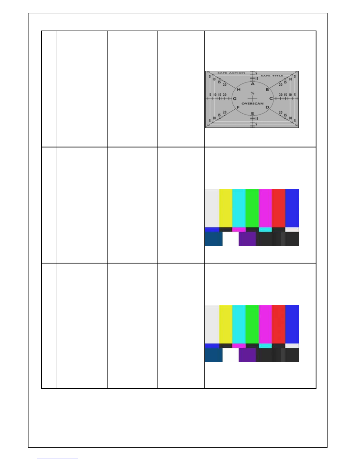
8
WINDOWS.
OVERSCAN (6%)
DVD
S-Video Cable
Video Cable
Play DVD test disc
VIDEO ESSENTIALS
Set DVD to
interlaced output
1. Select SOURCE then choose VIDEO or
SVIDEO.
2. Sending the signal from DVD test disc
(eighth paragraph)
3. Watch the screen to check if sees the
block screen within SAFE ACTION.
9
NTSC/PAL switch DVD
S-Video Cable
Video Cable
Play DVD test disc
VIDEO ESSENTIALS
Set DVD to
interlaced output
1. Select SOURCE then choose VIDEO or
S-VIDEO.
2. Sending the signal from DVD test disc
(sixth paragraph)
3. Switch DVD to output mode NTSC/PAL,
see if there is the action of switch
NTSC/PAL
10
480P/480i switch DVD
Component Cable
Play DVD test disc
VIDEO ESSENTIALS
Set the DVD to
progressive output
(P-SCAN)
1. Select SOURCE then choose VIDEO or
S-VIDEO.
2. Sending the signal from DVD test disc
(sixth paragraph)
3. Switch DVD output mode P-SCN ON/OFF,
see if there is the action of switch mode on
the screen.(480i/480p).

15
11
Audio adjustment Pattern Generator
Sound input
External connect
left-right
trumpet(10~15W/4)
Any Pattern
1. Select SOURCE
2. Then press MENU KEY enter AUDIO
adjustment item.
12 a. Volume
1. ,Key Set the sound volume.
2. Check if the action is normal.
b. Treble 1. Press,Key Set the high pitch volume
2. Check if the action is normal.
3. The initial value is ”16”
c. Bass 1. Press,Key Set the low pitch volume.
2. Check if the action is normal.
3. The initial value is ”16”
13
d. Balance
1. Press,Key Set the balance between
left-right trumpet.
2. Check if the action is normal.
3. The initial value is located at middle.
14 Language
adjustment
1. Select required language.
2. Initial value is set to English or set upon
clients’ requirement.

16
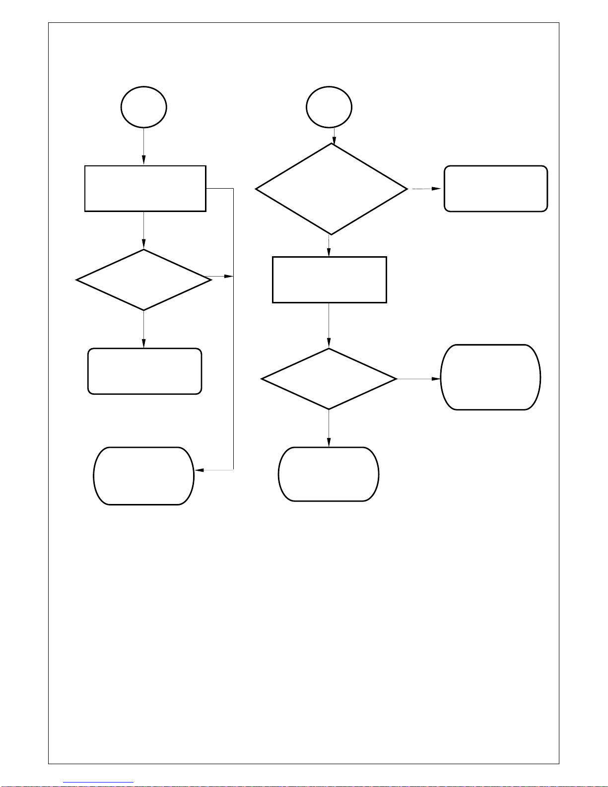
5. Trouble Shooting Flow Chart
STEP 1.
NO NO
YES YES
YES YES
NO
NO
NO
YES YES
NO
YES
OK NG NO YES
No Display
( Black )
LED ON ?
Push the power
ON/OFF switch
LED Color
change ?
Check IR/LED
board J1,U1,D1
Check Keypad
Board J1
p
in1
,p
in2.
LCD TV
ON?
Check
Video&
Audio
Function
Make sure the
LVDS
connection of
LCD Panel is
fine
CN3 Pin7
Active High?
Check the D-SUB
37Pin board CN3-
Pin7
Check Inverter
Power (24V)of
LCD Panel
,
OK?
B
Display ?
Check
Video&
Audio
Function
A Change AD
Board BOX
Check AC
Socket ?
Change AC
Socket Fuse
C
17
NO NO
OK
YES
YES
NO
YES
NO
B
CN3-PIN5
Active low(See
Panel SPEC.) ?
Change the LCD
Panel
Display ? Check Video&
Audio Function
Change AD
Board BOX
A
Check the connection
of Signal cable
Display ?
Check Video&
Audio Function
Change AD
Board BOX
Change AD Board
BOX

18
STEP 2.
NG
OK
STEP 3.
OK OK
NG
NG
No TV,VIDEO
and VGA
Picture
Change AD
Board BOX
No Audio
Change Speaker
Check
D-SUB
37pin
CON4
Check
Speaker
Check
Video&
Audio
Function
Change AD
Board BOX
Check
Video&
Audio
Function
Check
Video&
Audio
Function
OK
C
19
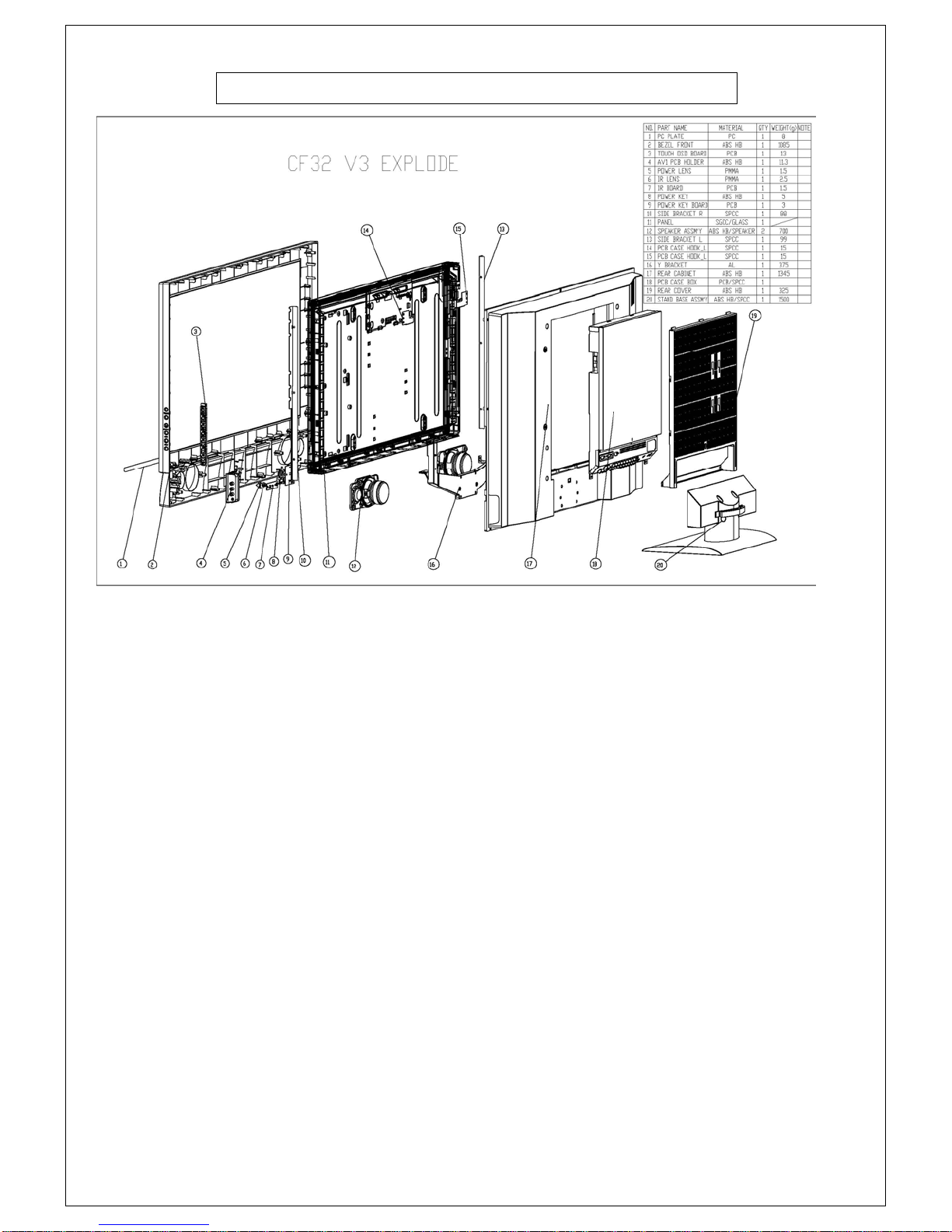
6. Exploded Diagram and Spare Parts List
Table of contents
Other Proview TV manuals


