PS Engineering PXE7300-SR User manual

200-739-0001 Rev. 2, January 2005
9800 Martel Road
Lenoir City, TN 37772
P
PX
XE
E7
73
30
00
0-
-S
SR
R
High-fidelity Stereo
In-Flight Entertainment System
With MP3/Compact Disc Player
AM/FM Radio Receiver
With Satellite Radio Option
FAA-STC/PMA Approved
Document P/N 200-739-0001
Revision 2
January 2005
Installation and Operation Manual
PS Engineering, Inc. 2005 ©
Copyright Notice
Any reproduction or retransmittal of this publication, or any portion thereof, without the expressed written permission of PS Engi-
neering, Inc. is strictly prohibited. For further information contact the Publications Manager at PS Engineering, Inc., 9800 Martel
Road, Lenoir City, TN 37772. Phone (865) 988-9800.
In certified aircraft, warranty is not valid unless this product is installed by an
Authorized PS Engineering dealer.

200-739-0001 Rev. 2, January 2005
Table of Contents
SECTION I GENERAL INFORMATION........................................................................ 1-1
1.1 INTRODUCTION........................................................................................................... 1-1
1.2 SCOPE ............................................................................................................................. 1-1
1.3 EQUIPMENT DESCRIPTION ..................................................................................... 1-1
1.4 APPROVAL BASIS ........................................................................................................ 1-1
1.5 SPECIFICATIONS......................................................................................................... 1-2
1.6 EQUIPMENT SUPPLIED ............................................................................................. 1-3
1.7 EQUIPMENT REQUIRED BUT NOT SUPPLIED .................................................... 1-3
1.8 APPROVED AUDIO SYSTEMS................................................................................... 1-4
1.9 LICENSE REQUIREMENTS ....................................................................................... 1-4
1.10 SUBSCRIPTION REQUIREMENTS (OPTION SR ONLY) ....................................... 1-4
SECTION II - INSTALLATION........................................................................................ 2-1
2.1 GENERAL INFORMATION ........................................................................................ 2-1
2.1.1 SCOPE ...........................................................................................................................2-1
2.2 UNPACKING AND PRELIMINARY INSPECTION................................................................ 2-1
2.3 EQUIPMENT INSTALLATION PROCEDURES .................................................................... 2-1
2.3.1 COOLING REQUIREMENTS .............................................................................................. 2-1
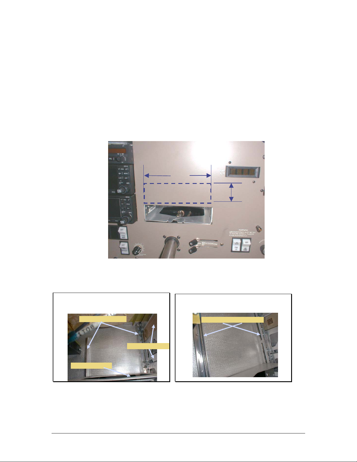
2.3.2 MOUNTING REQUIREMENTS........................................................................................... 2-1
2.3.3 PXE7300 MOUNTING RACK INSTALLATION.................................................................. 2-2
2.3.4 CONNECTOR ASSEMBLY ................................................................................................ 2-3
2.4 CABLE HARNESS WIRING................................................................................................ 2-3
2.4.1 NOISE ............................................................................................................................. 2-3
2.4.2 POWER............................................................................................................................ 2-4
2.4.3 BACKLIGHTING .............................................................................................................. 2-4
2.4.4 AM/FM ANTENNA ......................................................................................................... 2-4
2.4.5 UNSWITCHED SUMMED AUDIO ...................................................................................... 2-5
2.4.6 AUX ENTERTAINMENT AUDIO AND AUX ENABLE........................................................ 2-5
2.5 INTERNAL ADJUSTMENTS................................................................................................ 2-5
2.6 PSM7390 SIRIUS MODULE INSTALLATION .............................................. 2-5
2.6.1 MOUNTING RACK INSTALLATION .................................................................................. 2-5
2.6.2 SATELLITE RADIO ANTENNA INSTALLATION ................................................................ 2-6
2.7 POST INSTALLATION CHECKOUT ................................................................................... 2-7
2.8 UNIT INSTALLATION........................................................................................................ 2-7
2.8.1 SYSTEM CHECKOUT ....................................................................................................... 2-7
2.8.2 SIRIUS MODULE CHECKOUT ........................................................................................ 2-8
2.9 FINAL INSPECTION........................................................................................................... 2-9
SECTION III OPERATION ............................................................................................... 3-1
3.1 SCOPE ............................................................................................................................. 3-1
3.2 OPERATING CONTROLS................................................................................................... 3-1
3.2.1 POWER/VOLUME CONTROL (1) ...................................................................................... 3-1
3.2.2 STOP/EJECT BUTTON (2) ................................................................................................ 3-1
3.2.3 PLAY/PAUSE BUTTON (3)............................................................................................... 3-1
3.2.4 THE R/S BUTTON (4)...................................................................................................... 3-2
3.2.5 THE DATA KNOB (5) ...................................................................................................... 3-2
3.2.6 THE MODE BUTTON (6) ................................................................................................ 3-2

PS Engineering
PXE7300-SR IFE System
Installation and Operator’s Manual
200-739-0001 Page ii Rev. 2, January 2005
3.3 RADIO RECEPTION .......................................................................................................... 3-2
3.4 RADIO PRESET FUNCTION............................................................................................... 3-2
3.5 SIRIUS MODULE OPERATION........................................................................................ 3-3
3.5.1 SIRIUS SIGNAL DROP OUT: ..................................................................................... 3-4
3.6 DISPLAY DIMMING (7) ..................................................................................................... 3-4
SECTION IV- WARRANTY AND SERVICE.................................................................. 4-1
4.1 WARRANTY ...................................................................................................................... 4-1
4.2 FACTORY SERVICE .......................................................................................................... 4-1
APPENDIX A – MP3 CREATION ..................................................................................A
5.1 CREATING MP3S FROM AN AUDIO CD..............................................................................A
APPENDIX B – INSTALLATION DRAWINGS ......................................................... B
APPENDIX C CONNECTOR INTERCONNECT..............................................................C
APPENDIX D- STC INFORMATION AND INSTRUCTIONS FOR CONTINUING
AIRWORTHINESS ....................................................................................................................D
8.1 INSTRUCTIONS FOR FAA FORM 337, PXE7300-SR .........................................................D
8.2 INSTRUCTIONS FOR CONTINUING AIRWORTHINESS, PXE7300 SYSTEM........................D
8.3 MASTER DRAWING LIST ....................................................................................................D
8.4 USE OF APPROVED MODEL LIST .......................................................................................D
APPENDIX E RTCA DO160D/EUROCAE ED-14D ENVIRONMENTAL
QUALIFICATION FORM......................................................................................................... E
Table of Figures
Figure 2-2 Avionics Mounting Rails (Typical) ........................................................................................... 2-2
Figure 2-3 Completed panel opening (Typical) .......................................................................................... 2-3
Figure 3-1 PSM7390 Installation ................................................................................................................ 2-6
Figure 3-2 SR mounting Tray Hole Pattern ................................................................................................ 2-6
Figure 3-3 Typical Antenna Installation...................................................................................................... 2-7
Figure 3-1 Front Panel Controls.................................................................................................................. 3-1
Figure 7-1 Panel Location Drawing (Typical) 120-973-8801........................................................................B
Figure 7-2 PXE7300 Installation Diagram (Typical) 120-974-2488 ............................................................. C
Figure 7-3 Tray Installation Drawing, 002-973-0430 ....................................................................................D
Figure 7-4 - Satellite Radio Antenna Mounting NOT TO SCALE (120-230-2488)..................................... E
Figure 7-5 Circuit breaker installation drawing 120-973-8802 (typical) ....................................................... F
Revision History
Rev By Date Revision
1 GLP 2/2004 New STC release SA02795AT
2 GLP 1/2005 Added text regarding SIRIUS Satellite Radio signal availability

PS Engineering
PXE7300-SR IFE System
Installation and Operator’s Manual
200-739-0001 Page 1-1 Rev. 2, January 2005
Section I GENERAL INFORMATION
1.1 INTRODUCTION
Quality cockpit and cabin entertainment has long been an elusive dream in general aviation. Whether it was
marginal performance or unapproved parts, pilots couldn’t enjoy the same music in their aircraft as they
could in the family car. The marketplace needed a product designed, built and manufactured for general
aviation.
The PXE7300-Series represents such a product. This one unit combines a compact disk (CD) player with
MP3 capability and an AM/FM radio for ultimate in-flight entertainment capability.
The optional SIRIUS satellite Radio Module provides over 100 audio streams of entertainment, most of
them commercial free. These signals are available anywhere over the contiguous United States, so you
won’t lose your favorite station in flight.
Before installing and/or using this product, please read this manual completely. This will ensure that you
will take full advantage of all the advanced features in the PXE7300.
1.2 SCOPE
This manual provides detailed installation and operation instructions for the PS Engineering PXE7300-
series of IFE Systems. This includes the following units:
Model Part Number Description
PXE7300-SR 11970 Option -SR SIRIUS Satellite Radio receiver option
Where the functions are identical to all units, it will be referred to herein as a PXE7300. Otherwise, the
applicable units will be specified.
1.3 EQUIPMENT DESCRIPTION
The PXE7300 System is a single panel mounted unit that contains a CD player with MP3 media capability
and an AM/FM radio receiver. It also contains a high-fidelity stereo amplifier to provide the entertainment
output to the aircraft audio system.
An 8-digit LED display provides information about the systems, modes, and media in use.
1.4 APPROVAL BASIS
The PXE7300 is FAA approved FAA-STC SA02795AT and manufactured under PMA. PQ1336CE.
All systems comply with relevant portions of EUROCAE ED-14D/DO-160D (Environmental Conditions
and Test Procedures for Airborne Equipment), ED12B/DO-178B (Software Considerations for Airborne
Equipment) and ED- 18/DO-214 (Audio Systems Characteristics and Minimum Operational Performance
Standards for Aircraft Audio Systems).
STC SA02795AT can be used as a basis for approval in other aircraft provided the generic installation
manual, Document Number 200-739-0001 or later approved revision, is followed.
Advisory Circulars AC43.13-1B Acceptable Methods, Techniques, and Practices - Aircraft Inspection and
Repair, and 43.13-2A - Acceptable Methods, Techniques, And Practices - Aircraft Alterations are to be
used to resolve any issues not specifically addressed by the Installation Manual. Instructions for Continu-
ing Airworthiness (ICA) are provided in the supplied data.
Operation is subject to the following conditions:
This device may not cause harmful interference.
This device must accept any interference received, including interference that may cause undesired opera-
tion.

PS Engineering
PXE7300-SR IFE System
Installation and Operator’s Manual
200-739-0001 Page 1-2 Rev. 2, January 2005
1.5 SPECIFICATIONS
FAA-PMA COMPLIANCE
APPLICABLE DOCUMENTS: RTCA/DO-214
RTCA/DO-160D
RTCA/DO-178B (Level E)
ENVIRONMENTAL Qualifications: B1CABSXXXXXXZBBBAUHXXX
Temperature Range:
Operating:
Storage:
-15º C to 55ºC
-40º C to 85ºC
Altitude: Up to 25,000 feet in a non-pressurized area of the cockpit.
DIMENSIONS: Height: 2.0 in. (5.1 cm) Width: 6.25 in. (15.9 cm)
Depth: 7.7 in. (19.8 cm)
WEIGHT (With Rack & Connectors): 2.6 lb. (1.2 kg)
POWER REQUIREMENTS (Including Internal Lighting):
Voltage: 11 to 33 VDC
Maximum Current:
11970
11971
1.5 Amp (Externally protected by a 2 Amp circuit pull-
type breaker.)
2.5 A (Externally protected by a 5 Amp circuit pull-type
breaker.)
Typical operating current:
Lighting Current
800 mA
5 mA
Audio Specifications
Output Impedance: 150 - 1000 Ω
Audio Output: 38 mW each channel, no clipping <1% THD
Distortion: <1% THD
Music Freq. Response, 3 dB: 14 Hz –22 kHz
FCC Type Acceptance
Part 15 Verification to Part 15
Radio Tuning
North America AM: 530 – 1710 kHz, 10 kHz steps
FM: 87.7 – 107.9 MHz, 200 kHz steps
European (Option E) AM: 531 - 1602kHz, 9kHz steps
FM: 87.5 - 107.9MHz, 100kHz steps
PSM7390 SIRIUS Module
DIMENSIONS: Height: 5.5 in. (14.0 cm) Width: 1.50 in. (3.8 cm)
Depth: 7.75 in. (19.7 cm)
WEIGHT (With Rack & Connectors): 2.6 lb. (1.2 kg)
POWER REQUIREMENTS:
Voltage:
Maximum Current
11 to 33 VDC
0.9 Amp
(Power provided by PXE7300-SR Unit)

PS Engineering
PXE7300-SR IFE System
Installation and Operator’s Manual
200-739-0001 Page 1-3 Rev. 2, January 2005
1.6 EQUIPMENT SUPPLIED
1 ea. of the following units:
SIRIUS Radio Option, PXE7300-SR
Model Part Number Description
PXE7300-SR 11970, Option SR IFE System for use with SIRIUS Radio Module
PXE7300 Installation Kit: 250-730-0001
Part Number Description Quantity
430-730-0020 Tray 1
430-730-0025 Tray Shield 1
120-425-4402 44 Pin Connector Key 4/5 1
425-001-0002 Gold Plated Crimp Pins 30
475-440-0007 4-40x7/16" Phil-Pan w/Nylon Patch 4
475-630-0002 6-32 Clip Nut 6
475-632-0012 6-32 x ½ Phil-flat screws 6
202-730-00XX Pilots Guide 1
510-730-0001 Passive AM/FM Antenna 1
1.6.1 SIRIUS Radio Module
Model Part Number Description
PSM7390 010-731-1030 SIRIUS Radio Module
1.6.2 SIRIUS Radio Module Kit: 250-973-0500
430-739-5000 Mounting rack 1
475-739-5268 Mounting Screws, #8-32 x ½” 6
475-739-9600 Washers #8 12
475-739-0832 Self Locking Nuts, #8 6
425-000-1310 Satellite Antenna Connector (Blue) RG316 1
425-012-1759 Connector Housing (12 position) 1
425-040-1739 Connector Pins 8
1.7 EQUIPMENT REQUIRED BUT NOT SUPPLIED
a) Circuit Breaker, PULL TYPE: 1 ea. 5A
b) Aircraft Audio System (See section 1.8 for approved system list)
c) Interconnect Wiring
d) SIRIUS Satellite Radio Antenna (Antenna Specialists AT2300 PS E part Number 510-739-
2300, or equiv).
For antenna installation:
Doubler plate, p/n 430-230-2488, or equiv.
4 ea. #6-32 screws AN520 (or equiv.) SS PPHD
4 ea. #6 flat washer AN960 (or equiv.)
4 ea. #6-32 locking nuts (may be part of doubler plate or backing plate) MS21042-06 (or
equiv.)
Silicone sealer or other aviation type sealer
SMA Antenna Connector: PS P/N, 425-000-2211, Mfr P/N Tyco 221117-2
Pre-made SIRIUS Antenna Cable: 010-0316-0010 (10' cable)
010-0316-0020 (20' cable)

PS Engineering
PXE7300-SR IFE System
Installation and Operator’s Manual
200-739-0001 Page 1-4 Rev. 2, January 2005
1.8 APPROVED AUDIO SYSTEMS
This is a list of audio system that the PXE7300 should interface with adequately.
Approved Audio Systems, PXE7300
Certified interface is approved only for audio systems that are FAA-TSO approved.
Make Model Part Number
PM1000II 11920,11922
PM3000 11931, 11932
PMA6000-Series 6000 (all)
PMA7000-Series 7000 (all)
PCD7100 11950, 11951
PMA4000 11942
PS Engineering
PAC24 050-240-(all)
SL10-Series 430-6060-XXGARMIN AT
SL15-Series 430-6065-XX
Bendix/King KMA28 066-01176-0101
GARMIN International GMA340 010-00152-XX
1.9 LICENSE REQUIREMENTS
None
1.10 SUBSCRIPTION REQUIREMENTS (Option SR Only)
The SIRIUS Satellite Receiver requires an activation and periodic subscription. Monthly, annual and life-
time plans are available.
To activate the module, you will need to do the following:
• The SID/ESN number from your SIRIUS receiver.
• A major credit card.
• The SIRIUS tuner installed, the aircraft outside with a clear view of the sky.
• Turn your SIRIUS tuner on and tune it to channel 184.
When you activate online you pay only $5.00 at www.sirius.com. If you choose to activate by phone the
charge is $15. You can either call 1.888.539.SIRIUS (7474) or activate online.
Keep in mind that there may be additional fees when you activate, based on the following criteria:
• $5 charge to reactivate a receiver that has been inactive for over six months.
• $5 late fee for monthly payments made after bill due date.
• Printed copies of account information less than 18 months old cost $2.50 per request.
• Printed copies of account information more than 18 months old cost $10 per request.
• Termination of service prior to the end of a prepaid subscription or committed subscription period
will result in a $75 cancellation fee. Fee does not apply for monthly plans.
• You are responsible for all taxes or other government fees and charges, if any, based on the ad-
dress on your account.
NOTE: Prices subject to change without notice
Record your Radio ID here for future reference.
_________________________________

PS Engineering
PXE7300-SR IFE System
Installation and Operator’s Manual
200-739-0001 Page 2-1 Rev. 2, January 2005
Section II - Installation
2.1 GENERAL INFORMATION
NOTE: RECORD SIRIUS RADIO BEFORE DISCARDING BOX OR INSTALLING MODULE.
Record the number in space provided on page 1-4, Section 1.10.
2.1.1 SCOPE
These sections provide detailed installation and interconnect instructions for the PXE7300 In-Flight En-
tertainment System with integrated Compact Disc (CD/MP3) Media Player, AM/FM radio receiver and
remote mounted SIRIUS Radio Module (PSM7390).
Please read this manual carefully before beginning any installation to prevent damage and post-installation
problems. Installation of this equipment requires special tools and knowledge.
NOTE:
An appropriately rated Certified Aircraft Repair Station must install
this equipment in accordance with applicable regulations. PS Engi-
neering, Incorporated warranty is not valid unless the equipment is
installed by an authorized PS Engineering, Incorporated dealer. Fail-
ure to follow any of the installation instructions, or installation by a
non-certified individual or agency will void the warranty, and may re-
sult in an unairworthy installation.
2.2 Unpacking and Preliminary Inspection
Use care when unpacking the equipment. Inspect the units and parts supplied for visible signs of shipping
damage. Examine the unit for loose or broken buttons, bent knobs, etc. Verify the correct quantity of com-
ponents supplied with the list in Section 1.6 (B). If any claim is to be made, save the shipping material and
contact the freight carrier. Do NOT return units damaged in shipping to PS Engineering. If the unit or an
accessory shows any sign of external shipping damage, contact PS Engineering to arrange for a replace-
ment. Under no circumstances attempt to install a damaged unit in an aircraft. Equipment returned to PS
Engineering for any other reason should be shipped in the original PS Engineering packaging, or other
UPS approved packaging.
2.3 Equipment Installation Procedures
2.3.1 Cooling Requirements
Forced air-cooling of the PXE7300 and PSM7390 are not required. However, the unit should be kept away
from heat producing sources (i.e. defrost or heater ducts, dropping resistors, heat producing avionics) with-
out adequate cooling air provided.
2.3.2 Mounting Requirements
The PXE7300 must be rigidly mounted to the instrument panel or other structure of the aircraft structure
and within view and reach of the persons wishing access. Installation must comply with FAA Advisory
Circular AC 43.13-2A (or later revision). The unit may be mounted in any area where adequate clearance
for the unit and associated wiring bundle exist.
NOTE: The PXE7300 unit must be installed within ±30° of horizontal along the pitch axis, and ±10° of
horizontal along the roll axis in level flight.

PS Engineering
PXE7300-SR IFE System
Installation and Operator’s Manual
200-739-0001 Page 2-2 Rev. 2, January 2005
Avoid installing the PXE7300 close to high current devices or systems with high-voltage, pulse type out-
puts, such as DME or transponders.
The PSM7390 must be rigidly mounted to the aircraft structure in an area where avionics are typically in-
stalled, in accordance with FAA Advisory Circular AC 43.13-2A (or later revision) Chapter 2, Section 24,
and this manual.
2.3.3 PXE7300 Mounting Rack Installation
Remove the unit from the mounting tray by unscrewing the 3/32" hex-head screw that is near the left edge
of the unit. Carefully slide the unit free of the tray. Set the unit aside in a safe location until needed. Install
the tray using six FHP 6-32 x ½" screws. The unit must be supported at front and rear of the mounting tray.
See Appendix B.
The tray mounting can be made in any area that exists for adding additional avionics. Instrument panel
mounting is accomplished in accordance with AC 43.13-2A, Chapter 2.
Existing Structure (from behind
panel)
Avionics M ounting Rails
Existing T r ansponder
Center AvionicsStack
Factory Avionics Location
Factory AvionicsM ounting Rails
Figure 2-2 Avionics Mounting Rails (Typical)
2.00
”
6.31
”
Figure 2-1 Typical Panel Unit Installation Location

PS Engineering
PXE7300-SR IFE System
Installation and Operator’s Manual
200-739-0001 Page 2-3 Rev. 2, January 2005
Panel Opening
Saw and
file used to
remove
existing
instrument
panel from
this
location
Figure 2-3 Completed panel opening (Typical)
2.3.4 Connector Assembly
The unit connector mates directly with the circuit boards in the PXE7300. The connector (part number
120-425-4402 is a Molex crimp-type, and requires the use of a Molex hand crimp tool, EDP P/N 11-01-
0203, CR6115B (or equiv.). The connector is mounted to the unit tray with 2 ea. #4-40 screws, from the
inside of the tray. Ensure that proper strain relief and chafing precautions are made during wiring and in-
stallation.
B
A
C
120-425-4402
Connector
475-440-0007 (2 plcs)
Screws
Frontoftray
Rear
of tray
2.4 Cable Harness Wiring
Referring to the appropriate Appendix, assemble a wiring harness as required for the installation. All wires
must be MIL-SPEC in accordance with current regulations. Two- and three-conductor shielded wire must
be used where indicated, and be MIL-C-27500 or equivalent specification. Proper stripping, shielding and
soldering technique must be used at all times. It is imperative that correct wire be used.
Refer to FAA Advisory Circular 43.13-1B and 2A for more information. Failure to use correct techniques
may result in improper operation, electrical noise or unit failure. Damage caused by improper installation
will void the PS Engineering warranty. PS Engineering can provide a custom made harness, visit www.ps-
engineering.com for more information.
2.4.1 Noise
Due to the variety and the high power of radio equipment often found in today's general aviation aircraft,
there is a potential for both radiated and conducted noise interference.

PS Engineering
PXE7300-SR IFE System
Installation and Operator’s Manual
200-739-0001 Page 2-4 Rev. 2, January 2005
The PXE7300 power supply is specifically designed to reduce conducted electrical noise on the aircraft
power bus by at least 50dB. Although this is a large amount of attenuation, it may not eliminate all noise,
particularly if the amplitude of noise is very high. There must be at least 12 VDC present at the connector
pin 21, of the PXE7300 for the power supply to work in its designed regulation. Otherwise, it cannot ade-
quately attenuate power line noise. Shielding can reduce or prevent radiated noise (i.e., beacon, electric
gyros, switching power supplies, etc.) However, installation combinations can occur where interference is
possible. The PXE7300 was designed in a RFI hardened chassis and has internal Electromagnetic Interfer-
ence (EMI) filters on all inputs and outputs.
Ground loop noise occurs when there are two or more ground paths for the same signal (i.e., airframe and
ground return wire). Large cyclic loads such as strobes, inverters, etc., can inject noise signals onto the
airframe that are detected by the audio system. Follow the wiring diagram very carefully to help ensure a
minimum of ground loop potential. Use only Mil Spec shielded wires (MIL-C-275000, or better).
2.4.2 Power
The PXE7300-Series units are compatible with both 14 and
28 Volt DC systems. A five (5) Amp PULL-TYPE breaker is
required for PXE7300-SR. Power and ground wires must be a
twisted #18 AWG pair. Connect airframe power ground to
Pin 22 only.
See Appendix B for typical circuit breaker layout.
2.4.3 Backlighting
The PXE7300 has an automatic dimming of the pushbutton
annunciator LEDs controlled by a photocell. A dimmer control allows the bezel text backlighting to be
controlled by the aircraft dimmer. Connect the 14 V dimmer control to pin 1, the 28 V dimmer to pin A, as
required, using #22 AWG as a minimum size.
2.4.4 AM/FM Antenna
The passive AM/FM antenna, part number 510-730-0001 (included) is optimized for FM radio per-
formance. Therefore, when used for AM reception, the operator may only receive the most powerful
3 to 5 AM stations. In contrast to an ADF, where audio fidelity is not important, the PXE7300 re-
quires higher signal levels to ensure fidelity.
For optimum performance, some installers may desire an external AM/FM antenna. PS Engineering
recommends a Comant CI-222-series, installed in accordance with AC43.13-1A, Chapter 3.
Another AM performance-enhancing alternative is to connect the PXE7300 antenna input to an unused
VOR port of the VHF NAV antenna splitter. Do NOT add another splitter in series.
Figure 2-4 Circuit breaker location
(
T
yp
ical
)

PS Engineering
PXE7300-SR IFE System
Installation and Operator’s Manual
200-739-0001 Page 2-5 Rev. 2, January 2005
The included antenna can be mounted wherever convenient inside the cockpit, as long as it is in a window.
Verify that the antenna is not an impediment to crew vision outside the cockpit when installed,
For optimal operation, it should be near the windshield. Clean the mounting surface with appropriate
means (glass cleaner, etc), and apply adhesive (supplied with antenna). Route the antenna cable along edge
to the glareshield, and then connect to the PXE7300 connector. Avoid running the antenna cable near
high-current carrying wires, such as windshield heat, etc.
The antenna cable center conductor is connected to Pin 2, braid is connected to pin B.
2.4.5 Unswitched Summed Audio
PXE7300 units have four audio inputs that are summed together and presented to the audio output, J1 pin
18 WRT V.
NOTE: These can be used to implement additional audio warnings when connected to the appropriate
Unswitched audio input of an audio panel. This includes Autopilot warnings, TAWS, GPS alerts, Radio
Altimeter, etc.
2.4.6 Aux Entertainment Audio and AUX Enable
Besides the disc and AM/FM, the PXE7300 has the ability to act as a switching control for an additional
entertainment input (DVD, external XM Radio tuner, etc.).
The audio input is Pin 16 (R), Pin 17 (L) with respect to Pin K.
To enable the mode, add an internal jumper on the pins marked J2, or apply a ground to Pin 20 of the rear
connector.
2.5 Internal Adjustments
None
2.6 PSM7390 SIRIUS Module Installation
The PSM7390 SIRIUS Radio Module is a remote-mounted unit. This should be located in an area designed
for remote avionics.
2.6.1 Mounting Rack Installation
Attach the mounting rack to the avionics shelf using six (6) #8 x 32 screws, locking washers and nuts. Or,
install nut plates.
Make all installation in accordance with AC 43.13-2A Chapter 2, Section 24, or the aircraft maintenance
manual, or other accepted technical data.
Figure 2-5 Antenna Installation

PS Engineering
PXE7300-SR IFE System
Installation and Operator’s Manual
200-739-0001 Page 2-6 Rev. 2, January 2005
Aircraft Shelf
0.125" AL, 2024-T3
Mounting
nuts
3 ea. (M5)
6
ea.
Screws 475-739-5268
(AN526-832R8)
Mounting
split
washer
3 ea. (M5)
6 ea. #8 - 32 Nuts 475-739-0832, (AN365,) w 12 ea.
washers 475-739-9600 (AN960) or nut plates
430-790-5000
Mounting Rack
PSM7390
Radio Module
Figure 2-6 PSM7390 Installation
0.500in
2.500in 2.500in
7.500in
1.500in
Ø0.167in
Figure 2-7 SR mounting Tray Hole Pattern
2.6.2 Satellite Radio Antenna Installation
Antenna must be installed in accordance aircraft manufacturer instructions if applicable. Install in accor-
dance with antenna installation drawing 120-230-2488. Use doubler plate, p/n 430-230-2488, or equiva-
lent.
Provide a stable mounting base for the antenna and provide adequate clearance for the connector. Use a
backing plate or doubler plate as required by the installation to comply with FAA or aircraft manufacturers
advisory information.
Insure a continuous contact between the antenna O-ring seal and aircraft skin.

PS Engineering
PXE7300-SR IFE System
Installation and Operator’s Manual
200-739-0001 Page 2-7 Rev. 2, January 2005
Use silicone sealer between the antenna and the aircraft skin. Use four #6 stainless screws to secure an-
tenna to aircraft, using silicone sealer to seal the screws.
When routing the coax, avoid sharp bends, kinking or placement near aircraft control, power DME, trans-
ponder or radio communications cables. Careful attention must be given when securing the coax to the
airframe. Do not allow cable ties to crimp or crush the coax.
The antenna MUST be located on the top of the aircraft. Typically, the best location is on the aircraft cen-
terline, as close to the receiver module as practical. Installation should be centered between stringers, ± 1.0
inch, with a minimum 1.0-inch spacing to the structure.
Figure 2-8 Typical Antenna Installation
Any shadowing or signal blockage from the aircraft will degrade the performance of the SRR receiver.
Ideally, the antenna should have an unobstructed view of the sky above the horizon.
Coax cable loss not to exceed 7 dB. Select location to avoid interaction with other aircraft antennas. Mount
at least 24 inches from VHF Com transmitter antennas, at least 6 inches from other antennae.
2.7 Post Installation Checkout
After wiring is complete, verify power is ONLY on pin 21 of the connector, and airframe ground on bot-
tom connector pin 22. Failure to do so will cause serious internal damage and void PS Engineering's war-
ranty.
2.8 Unit Installation
To install the PXE7300, gently slide the unit into the mounting rack until the hold-down screw is engaged.
While applying gentle pressure to the face of the unit, tighten the 3/32" hex-head in the unit until it is se-
cure. DO NOT OVER TIGHTEN.
Warning: Do not over-tighten the lock down screw while installing the unit in tray.
Internal damage will result.
2.8.1 System Checkout
1. Insert disc, and verify that the player accepts the disk with about ½ of the diameter in the unit. The
player should pull the disk smoothly and drop into place.
2. The player will begin to play, automatically about 20 seconds (after reading the disc).

PS Engineering
PXE7300-SR IFE System
Installation and Operator’s Manual
200-739-0001 Page 2-8 Rev. 2, January 2005
3. If the unit is in disc mode, with CD inside at power-up, it will play (after reading the disc).
4. Verify that all Disc modes operate.
5. Push the “Eject” button and verify that the disc is ejected within about 10 seconds.
6. Verify radio operation on AM and FM
7. Verify that aux audio is presented to the output (if connected).
8. Evaluate the audio interface to be certain that the IFE audio is muted during intercom and radio com-
munication.
a. If muting override is provided, evaluate the switch location and verify operation.
b. Evaluate the audio performance
c. Evaluate the audio level to verify that the music is adequate under flight conditions.
d. Evaluate the muting system to demonstrate that the music will be adequately muted if de-
sired, by radio and intercom.
e. Evaluate the muting override control if equipped.
9. Evaluate failure remediation from crewmember location
a. Turn unit off
b. Locate and pull unit circuit breaker
c. With the disc playing, with minimum volume, listen to the following audio sources (as
equipped), adjusted to normal listening level:
i. Comm 1, comm. 2, comm 3, HF
ii. Nav 1, Nav 2
iii. ADF (1 and 2)
iv. DME (1 and 2)
v. Marker
vi. Any other audio sources
f. Select FM Mode, and repeat step 6, listening for interference on the aircraft audio
sources.
10. Select AM Mode, and repeat step 6, listening for interference on the aircraft audio sources.
11. Select COM 1 for transmit. Tune COM 1 to 118.00, and the PXE7300 to 107.3 MHz. Transmit a test
count and evaluate the unit display and audio output for inconsistencies
12. Repeat step 10 for COM 2, and other transmitters.
a. Tune Nav 1 to local station and perform a standard VOT test in accordance with 14 CFR 91.171.
b. Note the indicated VOR bearing on both systems.
c. Turn the PXE7300 on and off, and observe any change in the VOR indication that could be attrib-
uted to the PXE7300.
2.8.2 SIRIUS Module Checkout
Position the aircraft with a clear view of the sky.
1. Turn on the PXE7300-SR and cycle the “Mode” until SR shown in the display.
2. Select SIRIUS Channel 184 (preview channel).
3. Verify that the no error message appears in the display, and a valid audio stream is detected.
This may take a few minutes the first time the system is turned on.
4. Repeat step 8 in section 2.8.1.
5. Turn on all installed GPS systems, and verify that the signal levels do not degrade when the
PXE7300-SR is turned on and off.

PS Engineering
PXE7300-SR IFE System
Installation and Operator’s Manual
200-739-0001 Page 2-9 Rev. 2, January 2005
SIRIUS SIGNAL DROP OUT:
SIRIUS Satellite Radio uses ground-based transmitters in populated areas to ensure consistent road cover-
age. However, for airborne receivers, these ground-based signals may cancel satellite-transmitted signals,
resulting in a dropped signal. You may experience interruptions in the airborne SIRIUS signal near large
cities. This interruption will be variable, depending on AGL altitude, distance, number of ground-based
transmitters and azimuth to the transmitters.
PS Engineering, Inc. does not guarantee SIRIUS Satellite Radio coverage in all areas, or the suitabil-
ity of the SIRIUS Satellite Radio for any particular geographical area.
2.9 Final Inspection
Verify that the wiring is bundled away from all controls and no part of the installation interferes with air-
craft control operation. Move all controls through their full range while examining the installation to see
that no mechanical interference exists. Verify that the cables are secured to the aircraft structure in accor-
dance with good practices, with adequate strain relief. Ensure that there are no kinks or sharp bends in the
cables and coaxial cables. Verify that the cables are not exposed to any sharp edges or rough surfaces, and
that all contact points are protected from abrasion.
Complete logbook entry, FAA Form 337, weight and balance computation and other documentation as
required. Sample text for FAA Form 337 and instructions for continuing airworthiness can be found in
Appendix F.
Return completed warranty registration application to PS Engineering.

PS Engineering
PXE7300 SR SIRIUS Satellite Radio IFE System
Installation and Operator’s Manual
200-739-0001 Page 3-1 Rev. 2, January 2005
Section III OPERATION
GENERAL INFORMATION
3.1 SCOPE
This section describes the operation of the PXE7300 In-Flight Entertainment system.
Operating controls consist of two rotary knobs with push-push switches, and four buttons.
Figure 3-1 Front Panel Controls
3.2 Operating Controls
The single-disk player is designed for simple operation. The Disc player will begin to play automatically
when a Disc is inserted (unless the disc is specially formatted as 7300 volume, see section 3.4). The disc
will play through in order, and then stop at the end. If a disc is not inserted, the unit will be in the FM
radio mode.
NOTE:
When a disc is inserted, the display will show “Reading . . .” for up to 20 seconds, depending on the media
and amount of information contained.
3.2.1 Power/Volume Control (1)
The PXE7300 system is turned on and off by pushing the volume (left hand) knob. The left knob is the
volume control. Turning the knob clockwise will increase the volume.
3.2.2 Stop/Eject Button (2)
The Stop/Eject button will stop the disc. Hold for 3 seconds to eject the disc.
In AM or FM Radio Mode, this button scans up the frequency band for a strong signal.
3.2.3 Play/Pause Button (3)
Pressing the play/pause button momentarily will pause the player. Press for about one second to advance
the track or select another random track. Press and hold the PLAY/PAUSE to for an INTRO SCAN that
plays a few seconds of each track before advancing.
Momentarily pressing STOP/EJECT & PLAY/PAUSE buttons at the same time will cause the track to
jump backward.
NOTE:
The MP3 mechanism in the PXE7300 is more sensitive to scratches on the play side of the disc than tradi-
tional CD players. It is suggested to use CDs that have few to no scratches for optimum performance.

PS Engineering
PXE7300 SR SIRIUS Satellite Radio IFE System
Installation and Operator’s Manual
200-739-0001 Page 3-2 Rev. 2, January 2005
In AM or FM Radio Mode, this button scans down the frequency band for a strong signal.
3.2.4 The R/S Button (4)
This selects random or sequence play in the disc mode.
3.2.5 The Data Knob (5)
In the Disc mode (CD or MP3), the knob will advance (CW) or decrease (CCW) the track. Track number is
displayed when the knob is in motion. Then it will display the track name and then begin to play.
In AM or FM radio mode, this knob can be used to tune the radio directly.
If the playing media is an MP3 format, the pushing the DATA knob will display the data (if stored and
available) from the playing tracks in sequence when the knob is pushed.
Song Name
MP3 Actual File Name
Album
Artist
Depending on the total size of the information stored on the disc, the available data may be truncated in the
following manner: Small number of files, Actual File Name, Larger number of files, Truncated File Name,
Most files, Track Number.
If the SIRIUS Radio option is included, a long press will toggle between the channel number and the audio
stream name.
3.2.6 The MODE Button (6)
This button cycles through the operating modes;, Disc, FM, AM, SR and AUX (if enabled).
3.3 Radio Reception
The passive AM/FM antenna, part number 510-730-0001 (included) is optimized for FM radio perform-
ance. Therefore, when used for AM reception, the operator may only receive the most powerful 3 to 5 AM
stations. In contrast to an ADF, where audio fidelity is not important, the PXE7300 requires higher signal
levels to ensure fidelity.
For optimum performance, some installers may desire an external AM/FM antenna. PS Engineering rec-
ommends a Comant CI-222-L.
Another alternative is to connect the PXE7300 antenna input to an unused VOR port of the VHF NAV
antenna splitter. Do NOT add another splitter.
3.4 Radio Preset Function
The PXE7300 can save up to nine AM frequencies, nine, FM frequencies, and nine SIRIUS streams for
future recall. Select the desired radio frequency.
To set press the “R/S” button (4). The next available slot will be displayed as “S#.” (# being the available
memory location). Within five seconds, select the desired channel using the DATA knob (if not already
displayed). Press the R/S (4) again to save the selection. The display will flash, indicating a successful
save.
You can select the “S” slot by pressing the Stop (up) and play (down) buttons.
To access the channel, press the DATA knob (5) the radio mode, and select the preset with the DATA
knob or scan up (2) and down (3) buttons.

PS Engineering
PXE7300 SR SIRIUS Satellite Radio IFE System
Installation and Operator’s Manual
200-739-0001 Page 3-3 Rev. 2, January 2005
Action Disc Result Radio Result SIRIUS Result
▲short press Stop
▲long press Eject (also in AUX)
Frequency Scan Up No Change
►short press Pause
►long press Select next track/file and
keep playing or a random
track if in the random mode
Frequency Scan Down No Change
MODE press Change from FM to AM, to SR (if present), AUX to (if enabled) to DISC back to
FM
R/S press Toggle into Random or
Sequence play
Enter the preset “Set” mode Enter the preset “Set”
mode
DATA knob CW Select next track and play Increase radio frequency or
preset channel
Increment audio
Stream or preset
channel
DATA knob CCW Select previous track and
keep playing
Decrease radio frequency
or preset channel
Decrement Audio
Stream or preset
channel
DATA knob Push Show data on file (if
available)
Enter Pre-select Frequency
Recall Mode
Enter Pre-select
Frequency Recall
Mode, OR, Display
audio stream title if
held longer.
Table 1- PXE7300 Modes
3.5 SIRIUS Module Operation
The PSM7390 SIRIUS Satellite radio module is completely controlled by the PXE7300-SR unit. To acti-
vate, push the “Mode” button until SR and channel number, are displayed on the PXE7300. When the
module is activated by subscription, and the antenna has a clear view of the sky, SIRIUS audio will be pre-
sent in the entertainment system.
The SIRIUS audio stream can be selected with the “data” knob (5). Pressing the Data knob for more than 2
seconds will display the title of the audio channel.

PS Engineering
PXE7300 SR SIRIUS Satellite Radio IFE System
Installation and Operator’s Manual
200-739-0001 Page 3-4 Rev. 2, January 2005
3.5.1 SIRIUS SIGNAL DROP OUT:
NOTE: SIRIUS Satellite Radio uses ground-based transmitters in populated areas to ensure consistent road
coverage. However, for airborne receivers, these ground-based signals may cancel satellite-transmitted
signals, resulting in a dropped signal. You may experience interruptions in the airborne SIRIUS signal near
large cities. This interruption will be variable, depending on AGL altitude, distance, number of ground-
based transmitters and azimuth to the transmitters.
PS Engineering, Inc. does not guarantee SIRIUS Satellite Radio coverage in all areas, or the suitabil-
ity of the SIRIUS Satellite Radio for any particular geographical area.
3.6 Display Dimming (7)
The display is automatically adjusted for ambient light conditions by a photocell. The backlighting is ad-
justed by the aircraft dimmer circuit.
Table of contents
Other PS Engineering Receiver manuals