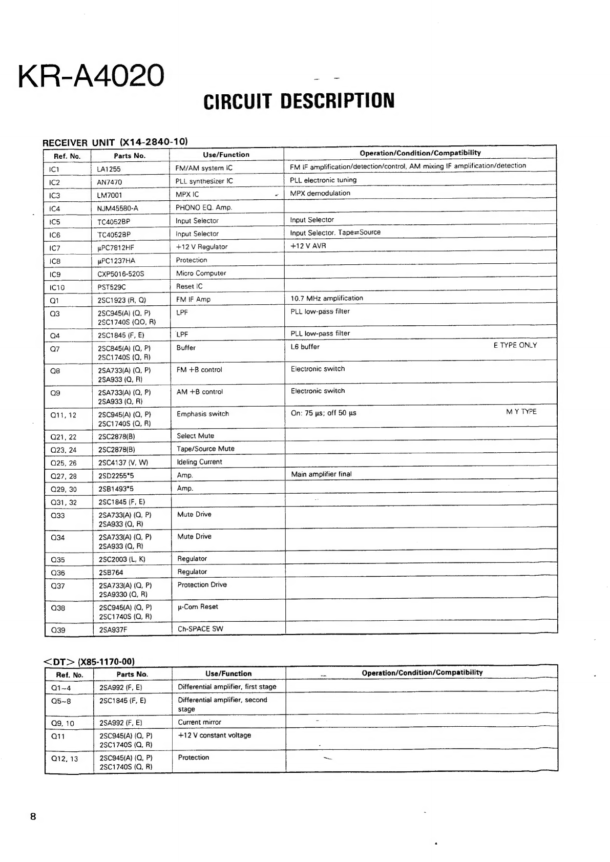
manuals.online logo
Brands
  1. Home
  2. •
  3. Brands
  4. •
  5. Kenwood
  6. •
  7. Receiver
  8. •
  9. Kenwood KR-A4020 User manual

Kenwood KR-A4020 User manual

KR-A4020
iobsiebahc
SERVICE
MANUAL
©1990-3
PRINTED
IN
JAPAN
B51-4138-00
(S)
3223
Front
glass
Metallic
cabinet
Knob
(VOLUME
CONTROL)
2
2
‘(A01-
4
= 7
(B10-1076-03)
Panel*
{A01-1832-01)
Knob
(TUNING)
{K29-3597-04)
(K29-3893-04)
Knob
(SPEAKER)
Knob
(K27-2006-04)
Knob
(BASS,
TREBLE,
BALANCE)
ees
(K29-3892-03)
(K29-3894-04)
x3
Binding
post
Phono
jack
(2P)
Lock
terminal
board
(8P)
AC
outlet?
AC
power
cord*
(NO8-0128-35)
(E13-0235-05)
(E20-0823-05)
(E03-)
{E03-)
Slide
switch
Lock
terminal
board"
Phono
jack
(8P)
Slide
switch
ealsetsi
te)
Power
cord
bushing
(E20-)
(E13-0820-05)
(S31-2136-05)
(J42-0083-05)
*
Refer
to
parts
list
on
page
28.
KR-A4020
CONTENTS
CONTROLS
AND
INDICATORS
........-.-..--+-+5:
SYSTEM
CONNECTIONS
...........-----
22-2
eee
ee
DISASSEMBLY
FOR
REPAIR...........------+++-+>
BLOCK
LEVEL
DIAGRAM
............----
522s
eee
CIRCUIT
DESCRIPTION
............6.2.
eee
e
ee
eee
ADJUSTMENT
........0.
000:
e
eee
eee
eee
eres
2
WIRING
DIAGRAM.....
4
PC
BOARD
............
5
SCHEMATIC
DIAGRAM
7
EXPLODED
VIEW......
8
PARTS
LIST
...........
13
SPECIFICATIONS
......
ee
ae
a
ee
ee
~.
t
1
H
H
H
Display
section
H
i
PHONES
jack
ee
ee
POWER
switch
MEMORY
key
Numeric
(1~
10/0)
keys
P.SCAN
key
VOLUME
CONTROL
knob
SPEAKERS
A
and
B
BASS
&
TREBLE
switches
control
knobs
Input
selector
keys
VULUME
CONTSOR
BALANCE
control
knob
DIRECT
key
TUNING
key
LOUDNESS
switch
AUTO
key
:
KR-A4020
CONTROLS
AND
INDICATORS
Display
section
STEREO
indicator
AUTO
indicator
TUNED
indicator
TAPE
indicator
MEMO.
indicator
|
AUTO
STEREO
TUNED
MEMO.
TAPE
TA
Wi
Ti AP
UD
ke
Hil,
LM
|
|
|
Ll
MHz
Frequency
display
Input
selector
display
Preset
channel!
display
KR-A4020
-
SYSTEM
CONNECTIONS
Make
connections
as
shown
in
the
diagram
below.
When
connecting
the
related
system
components,
refer
also
to
the
instruction
manuals
of
the
related
components.
a
Do
not
plug
in
the
power
lead
until
all
connections
are
complete.
Speaker
system
A
AC
outlets
for
U.S.A.
and
Canada
etc.
for
Austraka
for
Europe
and
U.K.
antenna
7]
a
wa
O
(peallvaa
FM
DE-EMPHASIS/
ca
CHANNEL
SPACE
switch
hy
<o
{Except
for
some
areas.)
metyehishe
selector
switch
{Except
for
some
areas.}
L»
UL
To
AC
outlet
CAUTION
n
ATTENTION
=
OPO
A
Hee
IH
anes
tate
She
tone
Turntable
(Turntable
using
MM
cartridge)
AUDIO
OUT
LINE
OUT
LINE
IN
CD
player
Tape
deck
VTR
(VCR)
Right
Left
Speaker
system
B
Notes;
———___—___________-_—_—_—
—_
1.
To
prevent
possible
problems,
always
disconnect
the
power
plug
or
turn
off
the
POWER
switch
of
the
receiver
before
connect-
ing
or
disconnecting
the
audio
cables.
2.
When
connecting
audio
cables,
always
insert
the
pin
plugs
s@-
curely
into
the
connecting
jacks.
@
Insufficient
insertion
may
result
in
no-sound problems
or
gener-
=
ation
of
noise.
a
KR-A4020
DISASSEMBLY
FOR
REPAIR
Note:
Remove
the
case
before
starting.
Removing
the
front
panel
and
sub-panel.
No.
1
1.
Remove
the
three
screws
1)
and
three
claws
@
at
the
bottom,
then
remove
the
front
panel.
2.
Remove
the
two
screws
(3)
at
the
front,
then
remove
the
sub-panel.
3.
Remove
the
TONE,
VOL,
and
BALANCE,
knobs
@
.
Remove
the
MAIN
VR
@
.
5.
Remove
the
nut
6)
and
screw
7)
,
then
remove
the
SP
switch
@
and
the
TONE
VR
@.
MAIN
VR
©.
and
BALANCE
VR
)
PC
boards.
s
Note:
To
remove
the
SP
changeover
switch,
remove
the
small
mold
®
,
then
remove
the
screw
:
1,
With
the
front
panel
held
as
shown
in
the
figure.
remove
the
screw
®
,
then
remove
the
display
PC
board
©
:
KR-A4020
a2
Removing
the
main
PC
board
Remove
the
sub-panel,
then
remove
the
main
PC
board.
The
main
PC
board
can
be
removed
even
if
the
front
panel
and
sub-panel
have
not
been.
No.
4
1.
Remove
the
two
screws
(B
holding
the
X14
PC
board.
2.
Remove
the
three
screws
(®
;
two
at
the
sides
and
one
at
the
center)
from
the
rear
panel.
3.
Remove
the
rear
panel
with
the
X14
board while
push-
ing
the
claw
®
at
the
side
of
the
rear
panel
with
a
flat-bladed
screwdriver.
How
to
remove
the
repairing
chassis
1.
Cut the
6
parts
@
of
the
repairing
chassis.
Remove
the
repairing
chassis
from
main
chassis.
After
repair
2.
Turn
the
repairing
chassis
180
degrees
in
the
arrow
di-
rection
@
.
3.
Insert
the
2
claws
©
into
main
chassis.
4.
Lock
to
the
main
chassis
by
2
screws
(M3
x
6)
OQ.
KR-A4020
wOivIns3y
>
2
mn
Ss)
<
"HO
YBHLONY
S3NOHd
8
1Sul4
2£0'89I
2ONv
va
cw
Ze
32
|
hs
wo?
[|
o3uais
691
>
=>
ss3Nqno1
ex
ae
‘dWY
Y3BMOd
:
szs
boars
ee
wanraee|
if
1
oun
o
Z3ainw
ce
vids
|
v-22S
aes
<sex>
10‘
o¢~s20
OQ
waa
aoe
<_<
|
oe]
:
ome
ESE
at
be
:
ic
jc
jmimip
+
baad fond
(a
Le
Bd
NOO-
anova]
|e
mali
|p|
—
frm
baa
Assit
f
Io
eh
Beco
rac)
Seog
[
|
Hovt
a
wSOTT
viva
>
0
o
Vv
<
AVIdSIGO
V4
14
|
oe
xnws
(©)
O30IA
©)
Avid>
Jd
vl
(©)
2au-
ino
3348
|
[(Oxze7AwooOZ
YBHLO
UNLb/
AWS?’
ONOHd
INV
WY
QNO
WY
inv
Wd
KR-A4020
Parts
No.
CIRCUIT
DESCRIPTION
RECEIVER
UNIT
(X14-2840-10)
Use/Function
Operation/Condition/Compatibility
LA1255
FM/AM
system
IC
FM
IF
amplification/detection/control,
AM
mixing
IF
amplification/detection
AN7470
PLL
synthesizer
IC
PLL
electronic
tuning
M7001
MPX
IC
MPX
demodulation
NJM45580-A
PHONO
EQ.
Amp.
TC4052BP
Input
Selector
Input
Selector
‘TC4052BP
Input
Selector
Input
Selector.
Tape=Source
uPC7812HF
+12
V
Regulator
+12
V
AVR
pPC1237HA
spi
Protection
CXP5016-520S
Micro
Computer
PST529C
ah
Reset
IC
2SC1923
(R,
Q)
FM
IF
Amp
10.7
MHz
amplification
2SC945(A)
(Q,
P)
2SC1740S
(QO,
R)
LPF
PLL
low-pass
filter
LPF
PLL
low-pass
filter
2SC1845
(F,
E)
2SC845(A)
(Q,
P)
2SC1740S
(Q,
R)
Buffer
L6
buffer
E
TYPE
ONLY
ag
Q11,
12
Tape/Source
Mute
Q23,
24
Q25,
26
Q27,
28
Q29,
30
2SA733(A)
(Q,
P)
2SA933
(Q,
R)
2SA733(A)
(Q,
P)
2SA933
(Q,
R)
2SC945(A)
(Q,
P)
2SC1740S
(Q,
R)
2SC2878(B
2SC4137
(V,
W)
2SB1493"5
=
FM +B
control
AM
+6
control
Emphasis
switch
Ideling
Current
2SD2255*5
Am
p.
Amp.
O31,
32
|
2SC1
845
(F,
E)
Electronic
switch
Electronic
switch
On:
75
us;
off
50
ps
Main
amplifier
final
2SA733(A)
(Q,
P)
2SA933
(Q,
R)
Mute
Drive
|
2SA733(A)
(Q,
P)
2SA933
(Q,
R)
Mute
Drive
2SC2003
(L,
K)
Regulator
2SB764
Regulator
+——
2SA733(A)
(Q,
P)
2SA9330
(Q,
R)
Protection
Drive
2SC945(A)
(Q,
P)
28C1740S
(Q,
R}
u-Com
Reset
<DT>
(X85-1170-00)
2SA937F
Ch-SPACE
SW
Use/Function
Operation/Condition/Compatibility
2SA992
(F,
E}
Differential
amplifier,
first
stage
2SC1845
(F,
E)
Differential
amplifier,
second
stage
2SA992
(F,
E)
Current
mirror
2SC945(A)
(Q,
P)
2SC17408S
(Q,
R)
2SC9465(A)
(Q,
P}
2SC1740S
(Q,
R)
+12
V
constant
voltage
Protection
-
KR-A4020
CIRCUIT
DESCRIPTION
1.
CXP5016-520S:
Receiver
microprocessor
(X14-284X-XX
:
IC9)
1-1.
Key
Matrix
connections
(F)
K
BACK
UP
CON.
Bee)
64
C185
47
N
PWM
Vop
+5V
mF/5.5V
KR:
KEY
RETURN
BACK
UP
PY2
WP
pyo
[S2=
Nc
fos
=
[62
PY3
EC
RMC
RES
(oe
peser
KRO
PXO
(4)
PxO
SC
KRO
EXTAL
XTAL
61
0
xi
4.194
MHz
SOB
KR1
0
SOA
KR2
INT1
S.
DATA
SI
KR3
inT2
[28
KR4
VFoPp
KRS
To
PS
1G
PD2
KR6
1155.
26
KR7
72
[24
3g
12}
aco
KSO
73/83.
ac
Pc1
KS1
T4O2.
56
ones
4
PC2
KS2
75
{2
Nc
a
PC3
KS3
16
N
PFO
KS4
17
NC
PTAPE
7348
nec
KR4
PDO
(8)
pours
18
1947.
si50
2
SELST
Si4n
]
DATA
$13m
CLOCK
$121
S11k
NC
$9i
NC
Sig
S6
f
S7e
S8d
$5c
S4b
S3a
PLL
LATCH
type
|
KRS_PD1(9)
3
ETvPEy
|
KR6
PD2
(10)
ee
Segments
LM7001
TC4052B8P
x2
1-2.
Setting
of
destinations,
models
and
specifications
depending
upon
diode
key
matrix
|
The
setting
of
destinations,
models
and
specifications
is
made
according
to
the
initial
set
diode
key
matrix.
|
In
the
following,
''1"'
means
‘with
diodes"
and
''0"',
"without
diodes".
1)
Model
Set
SW
Model
set
SW
Function
TYPE
TYPE
MODEL
DOLBY
VOL.
CONT
Switched
“|
SURROUND
_
|
with
Moter
VIDEO1,
2
nEMOEON
KR-V6020
(OTHER)
|FM1—FM2—AM|
Provided
Provided
Provided
Provided
KR-V6020
(E
TYPE)
Not
provided
KR-A5520,
A5020
:
Not
provided
KR-A4020
;
:
Not
provided
t
Not
provided
eee
KR-A4020
10
CIRCUIT
DESCRIPTION
1-3.
Initial
Setting
1)
Function
initial
setting
Last
channel
MEMON)..............0:c
ee
FM
:
87.5MHz
AM
({K)
:
530kHz
AM
(E)
:
531kHz
TUNING
MOE...
eee
eeee
eee
ceserteeteetseeeeneceeeenetinceetaes
Auto
INPUt
SCLECTOL
....
eee
eee
eeeceeeeeeeeteeeteeeteeeneeteeneeenes
FM1
MUtING
...ccccceccseesseeeeeeeeensceneeesecnesseeeeneeeneenateeeenesnes
OFF
2)
Microprocessor
output
port
initial
setting
Any
figure
in(
—)
is
a
pin
number.
MITE
W(25)
ccsscscceteceveses
cseresrcastccncustes
destepwactdaettteees
H
MUTE
23
(26)
vveticatvcocsshiesreecsscityecs
rie
bilenativentereces
H
The
initial
setting
is
performed
in
a
following
event
:
1.
When
backup
memory
data
is
destroyed
when
reset
is
applied
to
the
microprocessor.
2.
When
the
power
cord
is
plugged
in
to
the
AC
wall
outlet
while
pressing
the
TUNER
key.
1-4.
Test
Mode
Setting
1)
Method
of
entering
the
test
mode
1.
While
pressing
the
CD
key.
plug
the
power
cord
to
the
AC
wall
outlet.
When
the
test
mode
is
en-
tered,
the
FL
tube
display
all
lights.
2)
Method
of
canceling
the
test
mode
1.
Unplug
the
power
cord
from
the
AC
wall
outlet
once.
2.
Send
the
reset
signal
to
the
RESET
pin
or
some
other
means
to
reset
the
microprocessor.
3)
Contents
of
test
mode
1.
When
the
test
mode
is
entered,
the
FL
tube
display
all
lights.
This
all
lighting
continues
unless
a
effective
remote
control
serial
code
or
the
test
mode
is
can-
celed.
2.
The
test
frequency
is
stored
in
memory
for
each
preset
channel.
(For
each
frequency
to
be
stored
in
memory,
refer
to
its
associated
listing.)
1.
Frequency
memorized
for
each
PRESET
channel
when
the
memory
is
cleared
(Test
frequency)
Destination
K
E
K
E
K
£
1
87.5
MHz
87.5
MHz
|
87.5
MHz
87.5
MHz
530
kHz
531
KHz
3
90.0
90.0 87.5
87.5
990
990
4
92.0
92.0
87.5
87.5
1440
1440
*
Set
for
AM1700
only.
2.
Destination
set
SW
:
E
type/K
type
Destination
|
Desti-
setSW_
jnation
Reception
frequency
band
87.5
~108.0MHz
530
~1610kHz
530
~1700kHz
87.5
~108.0MHz
531
~1602kHz
10kHz
50kHz
6
98.0
|
98.0 87.5
87.5
1700*
531
7
|
100.1
100.1
t
87.5.
87.5
|
530
|
531
8
102.0
i
102.0
87.5
op
87.5
530
531
9
|
106.0
106.0
87.5
I
87.5
530
i
531
10
108.0
4108.0
87.5
87.5
530
§31
3.
Specification
set
SW
:
AM1700k/AM1610K
With
destination
set
SW
at
“0”
:
Effective
only
for
K
TYPE
Specification
set
SW
AM
reception
frequency
band
530
~1610kHz
530
~1700kHz
Pin
name
Name
KR-A4020
CIRCUIT
DESCRIPTION
Function
PY1
PY2
BACK
UP
RMC
N.C.
Backup
(AC
outlet
off)
detection.
High:
Normal
state
ine
Low:
AC
outlet
off
When
the
power
is
switched
on,
high
is
input.
When
low
is
input,
the
microprocessor
stops
clock
generation
and
enters
the
backup
state.
|
When
the
signal
changed
from
low
to
high,
the
backup
state
changes
to
the
normal
state.
GND.
PX0~PX3
PDO~PD3
KRO~KR7
High:
There
is
input.
Low:
There
is
no
input.
KEY
RETURN
signal
input.
PCO~PC3
PFO
KSO~KS4
|
KEY
SCAN
signal
output.
Normally
high
is
output.
i
Key
scan
is
performed
when
KEY
is
ON.
PFI
PTAPE
pPD4052
(select
IC)
control.
Tape
monitor
on/off
control.
PSEL2
PSEL1
(H9070)
DATA
|
pPD4052
(selector
IC)
control.
pPD4082
(selector
IC)
control.
.
LM7001(PLL
IC)
control
serial
data
output.
Data
is
latched
on
the
rising
edge
of
the
clock.
CLOCK
LM7001,
contro!
serial
data
transfer
shift
clock
output.
Data
is
latched
on
the
rising
edge
of
the
clock.
PLLLT
MUTE
1
MUTE
2
SD
STEREO
CE
—
output
to
LM7001.
When
the
signal
is
high,
LM7001
is
enabled.
High:
MUTE
OFF
Low:
MUTE
ON
Righ:
MUTE
OFF
Low:
MUTE
ON
TAPE
2
REC
OUT
mute
control.
LINE
OUT
mute
control.
N.C,
Tuner
tuned
detection.
High:
NO
SIGNAL
Low:
TUNED
High:
MONO
Low:
Stereo
Tuner
FM
stereo
detection.
Unused
pin.
Unused
pin.
Vss
GND.
S0~S14
Fluorescent
display
segment
drive
signal
output.
T8~T5
NC.
T4~TO
Fluorescent
display
digit
drive
signat
output.
Veop
INT2
Unused
pin.
This
pin
and
GND
are
shorted.
|
Unused
pin.
This
pin
and
GND
are
shorted.
INT1
This
pin
and
serial
data
input
pin
30
are
shorted.
Clock
generation
circuit
output.
Clock
generation
circuit
input.
Reset
signal
input.
+5
V
power
supply.
11
KR-A4020
a
CIRCUIT
DESCRIPTION
IC6TRUTH
TABLE
_|
ICS
TRUTH
TABLE
|
TAPE
SELECTOR
|
PINNO.
|
OUTPUT
PIN
NO.
|
L
ch@®,
R
ch®@
10!
a
Lch@®,Rch®
|
9
|
10
|
TAPEREC
|
Li
PHONO.
|
L
|
H
|
TAPE PLAY
H
|
CD
cure
TUNER
lide
VIDEO/AUX
|
H
|
H
Ic6
IC5
TC4052BP
TC4052BP
co
REC
PHONO.
OUTPUT
PLAY
TUNER
VIDEO/AUX
SEL1(1
9)
SEL2(1
8)
TAPE(1
7)
(
)
is
Pin
No.
of
u-Com
IC9
Switches
In/Out
Yop
YsV2¥1¥%oX3%Xo%Xi
Xo
ics
106
|
8
A
Commons
0
0
0
Yy Xo
TUNER
|
PLAY
Out/in
’
a
0 0
1
|
¥,
%
|
PHONO
FREC
0
1
0
Y, X,
i
cD
0
7
Y,
X;
|
VIDEO/AUX
1
x
|
x
12
KR-A4020
ADJUSTMENT
OUTPUT
TUNER
ALIGNMENT
INPUT
ie
TEM
SETTINGS SETTINGS
SETTINGS
POINTS
Gearon
ie
FM
SECTION
‘St
LECTOR:
FM
:
f
.
weeds
cd
rs
te
ass
wi
Si
es
SNe
ie
Sot
rr
oN
(A)
*
98.0
MHz
Connect
a
DC
AUTO
6
1
DETECTOR
i
voltmeter
between
or
MONO
OV
(a)
see
are
he
neey
TP14
and
TP15
98.0
MHz
ye!
|
60
dBp
(ANT
input)
;
ee
Chaasers
iecieneye
AUTO
VR2
2
VCO
:
counter
between
19.00
kHz
(b)
Ode
TP12
and
TP18
(GND)
Senne
Wes
100
dBy
(ANT
input)
Rs
(C)
98.0
MHz
DISTORTION
1
kHz,
+68.25
kHz dev
IFT
-.
Minimu
distortion.
:
(STEREO)
Selector:
Lor
R
(8)
eae
(Front
end)
(L or R)
Pilot:
+6.75
kHz
dev
\
|
60
dBp
(ANT
input)
(C)
4
SEPARATION
98.0
MHz
(B)
AUTO
VR3
Minimum
crosstalk
(E
type)
Stereo
signal
98.0
MHz
(X05-)
i
60
dBp
(ANT
input)
08.0
MH
AUTO
VR
Adjust
VR1
>
TUNING
LEVEL
0
dey
(B)
or
MONO
(X05-)
and
stop
at
the
point
18
dBu
(ANT
input)
98.0
MHz
|
where
FL1
(TUNED)
goes
on.
\M
SECTION
Keep
the
AM
loop
antenna
installed.
SELECTOR:
AM
(D)
vR4
Adjust
VR4
TUNING
LEVEL
1000
(999)
kHz
(B)
_
(X05-)
and
stop
at
the
point
26
dBu
(ANT
input)
where
FL1
(TUNED)
goes
on.
(ay;
AG
{_
|
FM-so
[|
(C)}
AG
[_]FM-MPxX
ae
AC
voltmeter
Voitmatre
CA
(B)
Wechselspan-
7
Oscilloscope
nungsmesser
Oscilloscope
Distortion
meter
Oszilloskop
Oistorsionmatre
Klirrfaktormesser
eo
es
os
es
auae
0
ueamescann
KR-A4020
14
REGLAGE
DE
REGLAGE
DE
REGLAGE
DU
POINT
DE
ie
aieinieae
=.
lets
ITEM
L'
ENTREE
LA
SORTIE
TUNER
L’
ALIGNEWEN
ALIGNER
POUR
Lb
ou
MONO
(x05-)
(a)
98,
OMHz
AUTO
vR2
,
98,
OMHz
(x05-)
(b)
Tate
HF.
(B)
98,
OMHz
IFT
(A)
98,
OMH2
1kHz.275kHz
dev
60dBu(Entrée
ANT)
(A)
98,
OMHz
0
dév
100dB,AEntrée
ANT)
(Cc)
98,
OMHz
1kHz.68,25kHz
dev
Selection:1
ou
R
Signal
pilote:
16,
75kH2z
dév
60dBu(Entrée
ANT)
(C)
98,
OMHz
Signal
stéréo
60dBu(Entrée
ANT)
Relier
un
voltadtre
AUTO
CC
entre
les
TPM
TPIS.
DETECTEUR
Relier
un
compteur
de
fréquence
entre
les
TP12(VOO)
et
TPISGND)
OSCILLATEUR
CONTROLE
PAR
LA
TENSION
DISTORSION
Distorsion
mininale.
(STEREO)
_
AUTO
08,
OMHz
SEPARATION
(CE
type)
Diaphonie
mininale.
(A)
98,
OMHz
AUTO
Ajuster
VR1
et
arréter
NIVEAU
0
dev
—
ou
MONO
le
mouvement
de
VRI
D’
ACCORDER
18dB,Entrée
ANT)
98,
0MHz
au
moment
750
00
le
FLICTUNED)s’
allume.
SECTION
MA
Laisser
|’
antenne
bouche
WA
installée.
|
SELECTEUR:
AW
Ajuster
VR4
et
arréter
a
NIVEAU
(A)
Je
mouvement
de
VR4
D’
ACCORDER
1000999)kHz
au
aoment
26dB,dEntrée
ANT)
oa
le
FLICTUNED)s’
allune.
ABGLEICH
EINGANGS-
AUSGANGS-
TUNER-
ABGLEICH-
GEGENSTAND
EINSTELLUNG
EINSTELLUNG EINSTELLUNG
ee
ABGLEICHEN
FUR
ABB.
UKW-EMPFANGSABTEILUNG
WAHLER:
Fil
(A)
98,
OMHz
Einen
Gleichspannungs-
AUTO
b
DETEKTOR
IkHz.+75kHz
Hub
messer
zwischen
TPli
oder
MONO
(x05-)
(a)
60dBuCANT-Eingang)
|
und
TPIS
anschlieGen.
98,
0MHz
:
(A)
SPANNUNGS
-
98,
OMHz
Einen
Frequenzzahler
AUTO
VR?
2
GEREGELTER
0
Hub
zwischen
TPI2VCO)
und
TPI&GND)
98,
0MHz
(x05-)
(b)
OSZILLATOR
100dB,4ANT-Eingang)
anschlieBen.
(c)
98,
OMHz
1kHz.
#68,
25kHz
Hub
Frontend
KLIRRFAKTOR
Wahler:
L
oder
R
(B)
98,
OMHz
IFT
(STEREO)
Pilotten:
(X05-)
£6,75kHz
Hub
60dBuCANT-Eingang)
(Cc)
STEREO
KANAL
98,
OMHz
AUTO
TRENNUNG
Stereo
Signal
(B)
98,
0MHz
(x05-)
Minimal
Klirrfaktor.
CE
Type)
60dBuCANT-Eingang)
(A)
98,
OMHz
AUTO
bi)
ABSTIMM
PEGEL
O
Hub
-
(B)
oder
MONO
VR
184B,{ANT-Eingang)
.
(X05-)
MW-EMPFANGSABTEILUNG
Die
M¥-Rahmenantenne
angebracht
lassen.
WAHLER:
AM
Den
Pegel
wiederstand
ABSTIMM
PEGEL
Den
Pegel
wiederstand
aufdrehen,
und
dem
VR1
Halt
geben
wobei
den
FLICTUNED)
anzeiger
leuchtet
wird.
aufdrehen,
und
dem
VR4
Halt
geben
wobei
den
FLICTUNED)
anzeiger
leuchtet
wird.
1000999)kH2
264B,AANT-Eingang)
~KR-A4020
WIRING
DIAGRAM
9/V
1;
O/V
DIX
'
vIX
$0-8992-107
V
3
vost
a
SONVIVa
SSSNGNO071
TOA/NIVW
9/8
Ix
LINN
WOO-7
9/0
IX
XVA
MOOZ
Sect
OOOO
009000
Soe
Q3H2LIMSNN
QUOD)
a
CUO)
(AINO
3dAL
Ht
BOS)
1A
cM
(AdAL
1‘°X)
thos
(3dAL
W)
tnoss05
~aovzav
V7
faqaaun
~aovz
-
022
V
bdddddddabddidedadehed
7021
-O1ldyv
—
f
=
(YANNL:
110-612-282)
(dW:
10-822S-287Z)
ef
LINA
YSA3I93yY
:
‘|
9/V
XX-Xv82-vIX
9/V
bIx
SO-2L99L-103:
4
GO-1992-
107°
%
2006413
d
2-691
32°»
$1-2992-107
\/
TWA
©“,
038
vase
(hata
O3HSLIMSNN
XVM
MO0z
v
Q3HOLIMAS
NN
cam
(AdAL
3)
twos
ci
as
~A0zz
Ov
aoziov
(3dALd'y)
VW
<M
15
2.
3
4
Q
4
band
F2
T2.5A250V
(a)
DETECTOR:
O
V
DC
Voltmeter
X14
F/6
8
vee
§
ooo
(b)
VCO:
19.00
kHz
6
7
‘
16
17
X14-284x-xx
Ref.
No
Address
Al
4G
2F
2E
pod
feo
pa
ond
Bw
9)
uu
uu
O;LO
WiWIDMSILILjOjx
fm)
nN
HIN
HIN]
MO]
St]
LO]
O/B
|
C01
OM]
O]
KIN]
OM]
+t]
LO]
OO;
|
CO]
ba
HL
HLAI
ANI
NINN
AN]
NN]
9]
09]
091.09)
09)
09)
09)
09/1
FI_Tt.25A
250V
X85-1170-07'
18
power
ee
en
re
ee
ne
re
enn
nen
nn
nnn
ne cr
nee
ncns
:
ere
:
1®
em
Frowr=eno(woz-oai-o8)
tt
ped
a
gg
—
7
1
rs
&
cr
cz
ce
FETI
ce
TRI
tet
|
Any
Jy
22°
1sP
L2
oP
oO
.
ap
8
“4
Geeanmmng
|,
cs
.
ef
v
S
ir
AT)
our
rj
°
A °
O
O
28
a)
I
, ‘
t
a
ae
!
bs
{
|
NC
3
a 4
wy
4
dj
R50
|
2
.
E
a
Ss
2
ano
fa
|
2
a
ao
an
FM
7
*1Orts
a
|
|
*
vo
[ot
AM
ANT
A
.
E20
ce
O~sp
FM
3.dv
cis
0.022
cia
0.022
RI
33K
cis
22007
pocccccc
ccc
rocco
2
|
=
H
*
1
|
.3SKIO1
|
2
28K241
ia
|
:
2sc2668
iol
1
2sc2995
[
*
:28¢2669
~~
_
ba
TESVIO3
|
|
L
!
i
Ici
[Fm
Tune
cever)
TUNE
LEVEL
x)
1@)
FM
FRONT-END
_
(WO2-1042-05)
|
!
[—
1
I
re
tax)
|
:
|
El
c2
c4
8
|
|
FM
ay
|
oO
ee
-
Et)
‘
|
s
300
GND
ey
i;
=
:
I
:
|
|
aq
y
£49
tics
4
|
AM
ANT
|
OF
|
|
,
ia
s
I
|
‘
|
a
oat
:
i
;
E20
TY
Re
a
a
|
|
I
aoc
fs
*e
a
"8
i
=
192.
!
v y
\
12,8.
I
|
by
5
!
hee
ee
eee
a
ee
!
!
.
:
|
1
|
*y
|
|
FET!
:28K241
1
I
TRI
1
28¢2668
|
3‘
1
| |
TR2
:28¢2995
|
“2
{
TR3
:28C2669
I
I
|
:
DI~3
:ISVIO3
I
{
am,|
|
1
bs)
I
3
ele
S\
+e
as
|
=
I
|
eq2
ele
Fa
a
ee
a
ee
eS
Aes
i
|
Lene
He
ae
SS
RSS
SR
SSE
SSS
Snes
Se
ee
een
ee
ey
cl
TLAIZ65
Ql
1
28C1923
(R.0)
1c2
tANT470
a4
1
28C1645
(F.E)
:
My
A
3
4
(
(Q.
P)
or
28C1740S
(Q.
R)
01.2.10.12.13!
188133
of
HSSIO4
2SA733(A)
2SA937F
2SA933S
2SC4137
NJM4558D-A
LM7001
18
aati
Gas
mone
:
eee
ie
io
Pp)
e
2549338
(Q.
R)
10
[ROS.
1ES(B2)
or
HZSS.
IN
(B2)
a
ec
ee
te
2SA992
28C1740S
Gasser
2SB764
resi,
62|
Pea.
64
aes
SEY
|
|
2SC1845
>
zex_|
3K
|
_NO
nO
ji
2SC1923
D6
‘3ex
|
30K
|
1.0K
bi
[No
[330K
_|
no
[No
[No
|
No
|
i
|
2SC2003
2c
®
eo
g
il
[amo_[
no
|
axe
[3a
[no
|
no_|
12x_|
4700
|
6|
-—-2SC2878
3
yu
!
2SC945(A)
:
i
i
.
|
|
DC
voltages
are
as
measured
with
a
high
impedance
voltme-
CAUTION:
For
continued
safety,
replace
safety
critical
compo-
{4
ter.
Values
may
vary
slightly
due
to
variations
between
indi-
nents
only
with
manufacturer's
recommended)
parts
(refer
to
|
AN7470
UPC1237HA
UPC7812HF
PST529C
LA1265
CXP5016-520S
vidual
instruments
or/and
units.
parts
list).
A
Indicates
safety
critical
components.
To
reduce
the
4052BP
:
:
i
*
i
'
TC405
ms
Ces
F
cc.
doi
atre
jaties
dvecam
volnute
a
risk
of
electric
shock,
leakage-current
or
resistame
measurements
‘
eens
ag
shall
be
carried
out
(exposed
parts
are
acceptally
insulated
from
haute
impédance.
Les
valeurs
peuvent
differer
legérement
du
2
d
Sais
wousased
;
4
the
supply
circuit)
before
the
appliance
is
returned
to
the
custom-
<
32
fait
des
variations
inhérentes
aux
appareils
et
aux
instruments
af
‘
<<
ourPur
*
de
mesure
individuels.
:
46
8
SSS
GND
Vee
8
INPUT
(Case)
our
SND
1
Die
angegebenen
Gleichspannungswerte
wurden:
mit
einem
t
hochohmigen
Spannungsmesser
gemessen.
Dabei
schwan-
7
1
ken
die
MeBwerte
aufgrund
von
Unterschieden
zwischen
ein-
ce
mes
Ae
mT
a
ON
NEOPETS
zeinen
Instrumenten
oder
Geraten
u.
U.
geringfiigig.
FM
TUNE
VCO
(I9KHz)
xo)
ng
ge
9
vco
Ic
2
c3e
o6visT)
4
S¥iMONO?
p12
ovtauToT)
|
|
:
_STveManuaty
5
D1
STEREO/MONO
SOKHE
pon
SY
ne
FLOP
rv)
AM
TUNE
LEVEL
=
FM
TUNE
LEVEL
a
O07
MHz
AE
3
;
eo
vind
zlos}]
5]
«
3
a
S330L
o3
©
0
«#3
=
3
3]
3]
8]
bt oT
Te
See
Bee
fet
ef
em
fe
o
o
ar
ato
ov
ez
2
58
22P
59
22
wRESY|
RE
75,
VOKHE
SO
~
SOKHr—=
100KHz
OKHE
“28C1923
(R.
0)
12801645
(F.
€)
l
T1st2
|
28C945
(A)
(0.P)
of
28C1740S
(Q
R)
OF.2.11
12.13:
1SSI33
of
HSSIO4
1
9
1
2SA7T33
(A)
(OP)
of
25A933S5(Q.R)
D110
DROS.
1€8(82)
of
HZSS5S.
IN
(82)
es
te]
nme]
oe
|
ee]
om
|
|
em
[oie
coma]
om:
fame
feseeleoem
lee]
en
|
NO
NO NO
NO NO
|
NO
|
150p
|
NO
[1.0450]
NO
[00224
NO
1.0K
NO NO
NO NO
1850p
|
NO
|1.0%50]
7500.
NO
NO
NO NO
NO
No
|
NO
|
150)
|
NO NO
NO
4700
270p_|
1500p
|
1300p
|
NO
|
1000p
|
220p
|2250[
NO
DC
voltages
are
as
measured
with
a
high
impedance
voltme-
CAUTION:
For
continued
safety,
replace
safety
critical
compo-
ter.
Values
may
vary
slightly
due
to
variations
between
indi-
nents
only
with
manufacturer’s
recommended
parts
(refer
to
vidual
instruments
or/and
units.
parts
list).
A
Indicates
safety
critical
components.
To
reduce
the
tisk
of
electric
shock,
leakage-current
or
resistance
measurements
shall
be
carried
out
(exposed
parts
are
acceptably
insulated
from
the
supply
circuit)
before
the
appliance
is
retumed
to
the
custom-
er.
NO
NO
NO
S.6mH
<=
a
co
NO
YES
[No
|
aE]
ee
NO
=
;
NO
YES
Les
tensions
c.c.
doivent
étre
mesurées
avec
un
voltmétre
a
haute
impédance.
Les
valeurs
peuvent
différer
legerement
du
fait
des
variations
inhérentes
aux
appareils
et
aux
instruments
de
mesur
individuels.
Die
angegebenen
Gleichspannungswerte
wurden
mit
einem
hochohmigen
Spannungsmesser
gemessen.
Dabei
schwan-
ken
die
MeBwerte
aufgrund
von
Unterschieden
zwischen
ein-
zeinen
Instrumenten
oder
Geraten
u.
U.
geringfigig.
co
(X14)
(076)
ee
eee
(x14)
(076)
1c9
:
CXP5016-520S
1c10
:
PSTS29C
a38
1:
28017405
(Q,R)
or
2S8C945(A110,
P)
a39
1
2SA937F
D41~43,45
:
HSSI104
or
1$$133
47,48
050
:
ROIOES
(B)
or
HZSION(B)
Ful
:
CPFS425GR
a.194am
Pees
1S
2
hs
ee,
von
6
(vruP)
©
GND
Roch
Loch
+t2V
STEREO
so
cE
CLK
DATA
CH
SPACE
(X14)
(D/6)
VCO
(I9KHz)
—_—
—_
——_—_-
—
(x14)
(076)
12
be
1c9
1
CXP5016-520S
1¢10
:
PSTS29C
(D)
Ic
2
036
:
28017408
(Q,
R)
or
28C945(A)
(Q,
P)
RSS
cat
3
3y80
Q39
:
2SA937F
(6)
ie
;
3
041~43,
45
:
HSS104
or
1SS133
cae
oy
30
2
Peers
47,48
;
‘
au
yay.
Shee
NS
45¥(
MONO?
050
:
ROIOES
(B)
Ss
or
HZSION(B)
Ful
:
CPFO4260R
(A)
——EH
By
=
Bt
PHASE
DETECTOR
RESET
O
¢soaTar®
0.08
C184
10010
(POWER) tSOATA)
(pusy)
cLocK
PLLLT
DATA
(VROOWN)
O(REMOCON)
\3\
>
O
PSEL!I
=
s
Hf
J
1B
TUNER
a
010
C57
47y
16
o36 001
Nias
gaa
eet mew
ok
1
Eee
|
F
ons
ent
ae
Adee
ct
3
ie
lO
SE
OOVO
ODO
OEGD
GND
PSEL2
Cc
«
1
came
Ln]is
=H
1
R
ch
woTez
=>
i
Nery
35
Loch
4
||
OM
=
5.6
le
3
*®
SI
~
ze
+12V
:
.
v
6
oOo
bul
ese
STEREO
8
ene
it
i:
i
;
he
z
-30v
oh
age
i
3
age
;
~
.
FILAMENT
=
;
Pies
‘
ee
3
FILAMENT
2
DATA
CH
SPACE
cra
100K
8
CH
SPACE
SW
KR-A4020
Y05-2470-11
bane
|
REC
VIDEO/
AUX
(X14-
284X-XX)(A/6)
Le
(X14-)(B/6)
|
=
"Twi
“
VR
OUTIR)
=
ee
u
@
es
3
3
z
s
>
Fy Fy
&
=
aie
a3
a
&
,
ES
sl
S228
Sw
é
32
=
By
3
&
2
ed
=
Fs
in
a
sas
ips
Sage
see
PgR
E2.33
z
Pees
fF
Eyes
zt
eget
2>9/>
+
©
zm
a
phd
®e26d62006
*
22
Fu
2
oz
°
Zaware
OO
tu
+
41¢
¢
|
@
ze
~~
Zz
br
Ook
Io
J)
|
GOGO
GOO
9OOQVOMND
MOHOOOOOOOOO)
QOOOODO®
=DOOAO
—
=
ee
(ea
cist
0.01
i
‘
ROI
c10l
A
Lael
eae
tea
"Laer
ae]
toy
3s
bs
.
eae
:
:
A
lll
ian
ler
|
=
Lt
fag
:
ane
ee
BEEEs
ue
HL
te
PRE
east
Saal
Ta
PT
|
ngs
F
moren
[Bare
en
ee
ae
AG
CP
Me
ee
46
tv
(38
av)
4.7050
Q37
eae’
4
Oy
Fee
eaee
ep
*Ci4d
JeCi4s
aciat
-a6.0V
{-38.6V)
20162
90147
6600P)
cas
6800P
La
220P
220P
eCiié
FeCiis
820K
|
620K
220P
220P
aCe
foci?
ci72
ci73
0.47p50
RI
oH
“©
RIBS
100K
100n35
039
034
8Q
or
MORE
OG
Pit
LESS
THAN
8N
GND
VR
OUTIL)
GNO
VROIN
(L)
GNO
VR
IN
(RD
So
ns
v7
a
22M172
Fe
ene
er
a
eg
a
a
a
oes
:
|
2
.
(X14
-=284X-xXx)
(A/6)
=
:
|
1C4
:NJM45580-A
28,
26
128C4137(V,W)
Q35
1
28C2003(L,K)
029
[HZS6.8
(B2)N
or
ROG.
BES
(B82)
1C5,6
:TC4052BP
027,28
‘:2sD2255¢5
036
:
288764
D31,
32
:S55668
ae
{
S25
|
1c?
[UPC78I2HE
029,
30
1288149365
D21~
26,
36,
37:
HSSI04
or
1SS133
D033,
38
:HSSIO4A
or
1SS13!1
1c8
[UPCI237HA
31,
32
[28C1@45(F,E)
027
DHZS3.
9N(B2)
or
RD3.
9ES(B2)
034
DHZSIGN(B2)or
RDIGES
(B2)
|
Q21~
24:
2802878
(B)
033,34,
37
:2SA733
(A)
(Q,P)
or
25A933S
(0,R)
D28,30
:HZS6.
2N(B2)
or
RD6.
2ES(B2)
035
:
RBV-402LFA
039
SHZSIIN(B2)or
ROIIES
(82)
SOOO.
—
ze
al
mc
3
Bspit)
1
Len
c
Asptt)
t
@sp(R)
I
Roh
fe
Asp(R)
It
+
———
Ll
Asp
re
5
re
°
[4
uw
|
FRO
xX
[SPE
+
&
a
Low
Bsp
R
+
ene

Other Kenwood Receiver manuals

Kenwood KMM-BT302 User manual

Kenwood

Kenwood KMM-BT302 User manual

Kenwood KMM-BT32U User manual

Kenwood

Kenwood KMM-BT32U User manual

Kenwood KR-X1000 Guide

Kenwood

Kenwood KR-X1000 Guide

Kenwood KMD-71 User manual

Kenwood

Kenwood KMD-71 User manual

Kenwood B60-0763-00 User manual

Kenwood

Kenwood B60-0763-00 User manual

Kenwood KR-V9080 User manual

Kenwood

Kenwood KR-V9080 User manual

Kenwood KRF-V6060D User manual

Kenwood

Kenwood KRF-V6060D User manual

Kenwood KRF-V4530D User manual

Kenwood

Kenwood KRF-V4530D User manual

Kenwood 1070VR User manual

Kenwood

Kenwood 1070VR User manual

Kenwood KRF-V7771D User manual

Kenwood

Kenwood KRF-V7771D User manual

Kenwood DPX305MBT User manual

Kenwood

Kenwood DPX305MBT User manual

Kenwood KRF-V5010 User manual

Kenwood

Kenwood KRF-V5010 User manual

Kenwood KMD-PS971R/X92 User manual

Kenwood

Kenwood KMD-PS971R/X92 User manual

Kenwood KR-V87R User manual

Kenwood

Kenwood KR-V87R User manual

Kenwood KMM- BT508DAB User manual

Kenwood

Kenwood KMM- BT508DAB User manual

Kenwood RFU-R6100 User manual

Kenwood

Kenwood RFU-R6100 User manual

Kenwood IR-9991 User manual

Kenwood

Kenwood IR-9991 User manual

Kenwood R-600 User manual

Kenwood

Kenwood R-600 User manual

Kenwood KVT-715DVD User manual

Kenwood

Kenwood KVT-715DVD User manual

Kenwood SMB 2700 User manual

Kenwood

Kenwood SMB 2700 User manual

Kenwood KRF-V6030D User manual

Kenwood

Kenwood KRF-V6030D User manual

Kenwood TS-790A User manual

Kenwood

Kenwood TS-790A User manual

Kenwood AR-404 User manual

Kenwood

Kenwood AR-404 User manual

Kenwood R-2000 User manual

Kenwood

Kenwood R-2000 User manual

Popular Receiver manuals by other brands

Yamaha HTR 6250 - AV Receiver owner's manual

Yamaha

Yamaha HTR 6250 - AV Receiver owner's manual

Yamaha RXV765 - RX AV Receiver owner's manual

Yamaha

Yamaha RXV765 - RX AV Receiver owner's manual

Denon AVR-486S Specifications

Denon

Denon AVR-486S Specifications

a-them AVM 90 operating manual

a-them

a-them AVM 90 operating manual

SaskTel maxTV Stream Quick start guides

SaskTel

SaskTel maxTV Stream Quick start guides

FUTABA R2008SB manual

FUTABA

FUTABA R2008SB manual

CSI Wireless DGPS MAX Reference manual

CSI Wireless

CSI Wireless DGPS MAX Reference manual

Harman Kardon AVR 340 reference guide

Harman Kardon

Harman Kardon AVR 340 reference guide

Pioneer VSX-D407 Service manual

Pioneer

Pioneer VSX-D407 Service manual

unication BR 01 manual

unication

unication BR 01 manual

Williams Sound WIR RX14 Instructions for use & care

Williams Sound

Williams Sound WIR RX14 Instructions for use & care

Herutu TW-800R-SLNX instruction manual

Herutu

Herutu TW-800R-SLNX instruction manual

Harman Kardon AVR 300 owner's manual

Harman Kardon

Harman Kardon AVR 300 owner's manual

Sony SAT-HD300 - High Definition Satellite... Specifications

Sony

Sony SAT-HD300 - High Definition Satellite... Specifications

Pioneer DEH-X1952UB owner's manual

Pioneer

Pioneer DEH-X1952UB owner's manual

Pioneer Elite VSX-43 quick start guide

Pioneer

Pioneer Elite VSX-43 quick start guide

Cypress COH-Tx Operation manual

Cypress

Cypress COH-Tx Operation manual

Yamaha RX-A1000 owner's manual

Yamaha

Yamaha RX-A1000 owner's manual

manuals.online logo
manuals.online logoBrands
  • About & Mission
  • Contact us
  • Privacy Policy
  • Terms and Conditions

Copyright 2025 Manuals.Online. All Rights Reserved.