PSG Dover Mouvex B200 Flow Control User manual
INSTRUCTIONS 1401-X00 e
Section 1401
Effective October 2018
Replaces February 2017
Original instructions
B200 Flow Control
SCREW COMPRESSORS
INSTALLATION
OPERATION
MAINTENANCE
SAFETY
STORAGE
Your distributor :
Z.I. La Plaine des Isles - F 89000 AUXERRE - FRANCE
Tel. : +33 (0)3.86.49.86.30 - Fax : +33 (0)3.86.49.87.17
WARRANTY :
B200 Flow Control compressors are covered 36 months by warranty within the limits mentioned in our General Sales
Conditions. In case of a use other than that mentioned in the Instructions manual, and without preliminary agreement of
MOUVEX, warranty will be canceled.
12R/10L PF12R/10L PS 12R/10L HY
2/22
NT 1401-X00 10 18 B200 Flow Control e
MOUVEX TRUCK SCREW COMPRESSOR
SAFETY, STORAGE, INSTALLATION, OPERATION AND MAINTENANCE INSTRUCTIONS
MODEL : B200 Flow Control
REMARKS :
MOUVEX truck screw-type compressors MUST be installed in sys-
tems designed by qualified personnel. The installation MUST be in
compliance with local standards, national regulations and rules of
safety.
This manual is designed to permit installation and commis-
sioning of MOUVEX truck screw-type compressors and MUST
accompany the compressor.
Maintenance of MOUVEX screw-type compressors must ONLY
be carried out by qualified technicians. This maintenance must
meet local and national standards as well as all safety regula-
tions. Read this manual, including all instructions and warn-
ings, in full BEFORE any use of MOUVEX compressors.
Reading and the removal of the labels on the MOUVEX com-
pressor apply to approval.
1. OVERALL DIMENSIONS . . . . . . . . . . . . . . . . . . . . . . . . . .4
2. GENERAL DATA . . . . . . . . . . . . . . . . . . . . . . . . . . . . . . . .7
2.1 Principle of operation . . . . . . . . . . . . . . . . . . . . . . . . . .7
2.2 Technical characteristics . . . . . . . . . . . . . . . . . . . . . . . .7
2.3 Operating ranges . . . . . . . . . . . . . . . . . . . . . . . . . . . . .8
3. INSTALLATION . . . . . . . . . . . . . . . . . . . . . . . . . . . . . . . .10
3.1 B200 PF with truck power take-off . . . . . . . . . . . . . . .10
3.2 B200 PS with drive shaft . . . . . . . . . . . . . . . . . . . . . .12
3.3 B200 HY with hydraulic motor . . . . . . . . . . . . . . . . . .13
3.4 Piping . . . . . . . . . . . . . . . . . . . . . . . . . . . . . . . . . . . . .14
4. USE OF COMPRESSOR . . . . . . . . . . . . . . . . . . . . . . . . . .17
4.1 Lubricant recommendations . . . . . . . . . . . . . . . . . . . .17
4.2 Filling of lubricant . . . . . . . . . . . . . . . . . . . . . . . . . . . .17
4.3 Operation . . . . . . . . . . . . . . . . . . . . . . . . . . . . . . . . . .17
5. MAINTENANCE . . . . . . . . . . . . . . . . . . . . . . . . . . . . . . . .18
5.1 Maintenance schedules . . . . . . . . . . . . . . . . . . . . . . .18
5.2 Compressor oil change . . . . . . . . . . . . . . . . . . . . . . . .18
5.3 Inlet shaft replacement . . . . . . . . . . . . . . . . . . . . . . . .19
5.4 Warranty claims . . . . . . . . . . . . . . . . . . . . . . . . . . . . .19
6. TROUBLESHOOTING . . . . . . . . . . . . . . . . . . . . . . . . . . .20
7. STORAGE CONDITIONS . . . . . . . . . . . . . . . . . . . . . . . . .20
7.1 Compressor . . . . . . . . . . . . . . . . . . . . . . . . . . . . . . . .20
7.2 BSC2 oil . . . . . . . . . . . . . . . . . . . . . . . . . . . . . . . . . . .20
8. SCRAPPING . . . . . . . . . . . . . . . . . . . . . . . . . . . . . . . . . .20
9. COMPRESSORS FORM INFORMATION . . . . . . . . . . . . .21
10. CERTIFICATE OF CONFORMITY . . . . . . . . . . . . . . . . .22
TABLE OF CONTENTS Page
ADDITIONAL DOCUMENTATION
The table below gives the list of instructions in addition
to this central instruction :
B200
application
Spare parts
list
Torque limiter NT 1401-AB00
Air cooler NT 1401-AD00
12R/10L PL 1401-X01
Definition of safety symbols
This is a SAFETY ALERT SYMBOL.
When you see this symbol on the product, or in the manual,
look for one of the following signal words and be alert to the
potential for personal injury, death or major property damage.
Warns of hazards that WILL cause serious personal injury,
death or major property damage.
Warns of hazards that CAN cause serious personal injury,
death or major property damage.
Warns of hazards that CAN cause personal injury or property
damage.
NOTICE
Indicates special instructions which are very important and
must be followed.
DANGER
WARNING
CAUTION

SAFETY CHECK LIST
1. Before operating the compressor, ensure the vessel to which the
compressor is connected is certified to withstand the pressure and
/or vacuum produced.
2. Verify adequately sized relief valves have been fitted to protect the
vessel. Do not use solvents or inflammable products for cleaning
the pipelines and the accessories.
3. Gas/air mixtures which are potentially volatile/explosive must not be
introduced or allowed to be introduced into the compressor.
4. All pressure vessel and piping connected to the compressor must
be isolated and in a safe operating condition.
5. Operators should wear ear protection when operating truck mount-
ed compressors.
6. There are components within the compressor of sufficient weight
to cause injury if mishandled. Use proper lifting devices as neces-
sary.
7. Where necessary, this equipment should be grounded to control
static electricity.
8. The temperature of the air leaving the compressor is elevated
above ambient due to air compression. Check that the elevated
temperatures do not adversely affect the product and any material
used in design of the system. Attach clearly marked warning signs
to warn of potentially hot surfaces on the compressor, piping and
accessories which will burn if touched.
9. Mounting of the compressor must be correctly engineered and the
compressor must be properly secured. Refer to the Compressor
Mounting section of this manual.
NOTICE :
MOUVEX COMPRESSORS ARE DESIGNED TO PRODUCE COM-
PRESSED AIR. NOT TO PUMP LIQUIDS, LIQUEFIED GASSES OR
POWDERS THOUGH THE COMPRESSOR. TO DO SO WOULD VOID
THE WARRANTY.
LIFTING POINTS :
The compressor can be picked up from underneath to be
transported.
Discharge flanges threads can be used to install a lifting lug
in order to transport the compressor.
WARNING
IT IS IMPERATIVE TO APPLY THE
TRUCK PARKING BRAKE AND TO
BLOCK THE WHEELS BEFORE ANY
INTERVENTION DUE TO RISKS OF
SERIOUS BODILY INJURIES OR PRO-
PERTY DAMAGE.
Hazardous machinery
can cause severe
personal injury or
property damage.
WARNING
COMPRESSING GASES INTO A VES-
SEL CONTAINING FLAMMABLE OR
EXPLOSIVE GASES OR COMPRESSING
FLAMMABLE OR EXPLOSIVE GASES,
CAN CAUSE PROPERTY DAMAGE,
PERSONAL INJURY OR DEATH.
Hazardous fluids
can cause fire,
serious personal injury
or property damage.
WARNING
FAILURE TO INSTALL ADEQUATELY
SIZED PRESSURE RELIEF VALVE(S)
CAN CAUSE PROPERTY DAMAGE,
PERSONAL INJURY OR DEATH.
Hazardous pressure
can cause
personal injury
or property damage.
CAUTION
COMPRESSOR, PIPING AND ACCES-
SORIES WILL BECOME HOT DURING
OPERATION AND CAN CAUSE SERIOUS
PERSONAL INJURY.
Extreme heat can
cause injury or
property damage.
WARNING
CONTENTS OF THE COMPRESSOR,
TANK, PIPING, AND FILTERS COULD
BE HAZARDOUS TO HEALTH.
TAKE ALL NECESSARY PRECAUTIONS
WHEN PERFORMING COMPRESSOR
SERVICE OR MAINTENANCE.
Hazardous or toxic
fluids can cause
serious injury.
WARNING
THE NOISE EMITTED BY WORKING
MOUVEX SCREW COMPRESSOR
CAN BE HIGHER THAN 80 DBA.
THE END USERS MUST USE, WHEN
NECESSARY THE APPROPRIATE
EAR PROTECTIONS. FAILURE TO
WEAR HEAR PROTECTIONS IN
AREAS WHERE THE NOISE IS
HIGHER THAN 80 DBA CAN LEAD TO
PERMANENT BODY DAMAGE.
A loud noise can
cause permanent
body damage.
3/22
NT 1401-X00 10 18 B200 Flow Control e
SAFETY DATA

4/22
NT 1401-X00 10 18 B200 Flow Control e
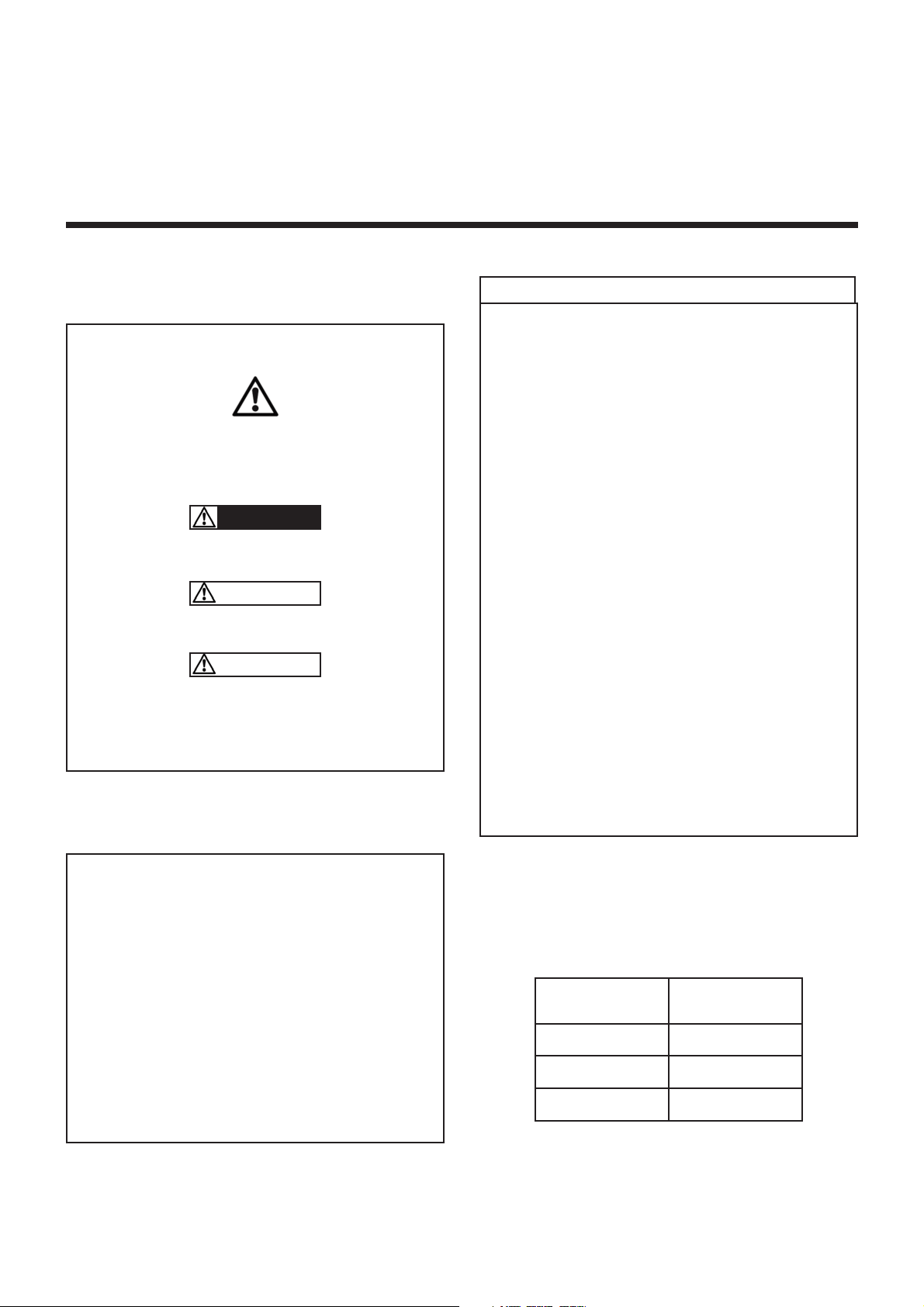
1. OVERALL DIMENSIONS
Identification plate
4 holes Ø 12,5
Swivel cover
Drain plugs
Breather plug
Plug : speed measure
Oil gauge
Oil fill plug
Flange 1,5”
BSP
Splines B8x32x36 DIN 5462
2 holes M10x15
2x 3 holes M10x15
Direction of rotation
MALE SPLINED SHAFT VERSION = PF
MALE KEYED SHAFT VERSION = PS
B200 12R/10L
PS & PF
Weight : 26,3 kg
Serial number
stamped on the body
5/22
NT 1401-X00 10 18 B200 Flow Control e
1. OVERALL DIMENSIONS (continued)
Identification plate
6 holes Ø 10,2
Swivel cover
Drain plugs
Breather plug
Plug : speed measure
Oil gauge
Oil fill plug
Flange
1,5” BSP
2 holes M10x15
2x 3 holes M10x15
Direction of rotation
B200 12R/10L
HY
Splines ANSI B92-1a
7/8” SAE_16/32 13 teeth
Weight : 26,8 kg
FEMALE SPLINED SHAFT VERSION
FOR HYDRAULIC DRIVE = HY
Serial number
stamped on the body
6/22
NT 1401-X00 10 18 B200 Flow Control e
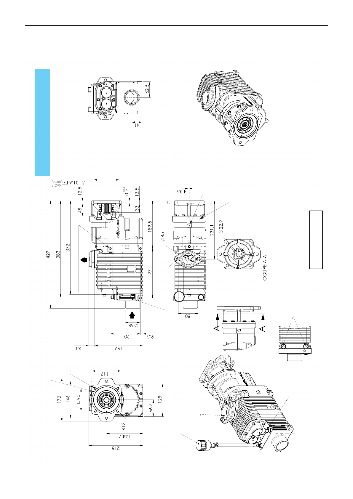
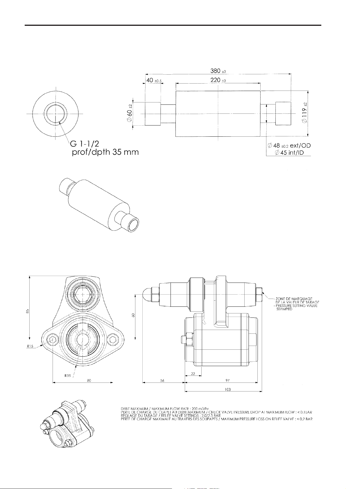
1. OVERALL DIMENSIONS (continued)
SILENCER DN 40
CHECK AND RELIEF VALVE
7/22
NT 1401-X00 10 18 B200 Flow Control e
2. GENERAL DATA
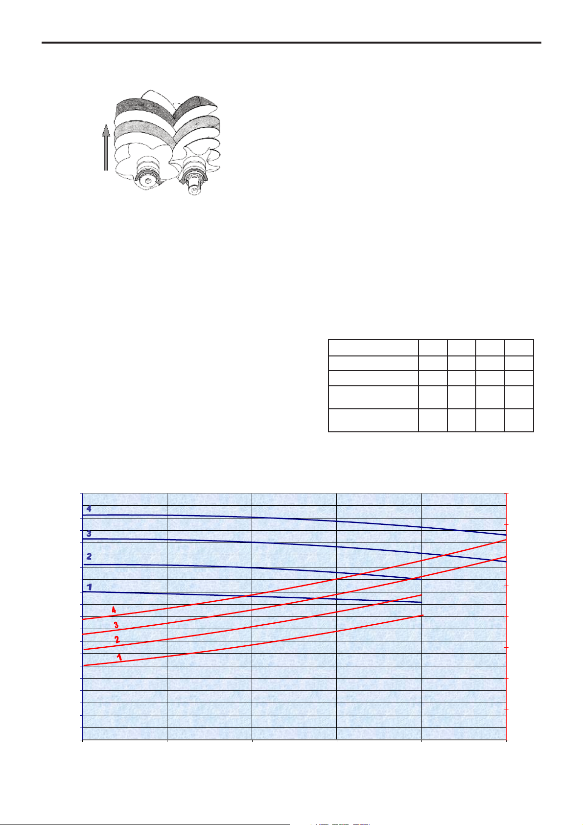
2.1 Principle of operation
The male screw and the female screw mesh and rotate
in opposite directions inside the casing fitted with inlet
and discharge ports.
Rotation generates a volume increase on the inner face
between threads and grooves, which corresponds to
inlet, and a volume reduction on the upper face, which
corresponds to compression.
On the discharge port side, a set of gears synchronizes
the male screw and the female screw. Thus, the screws
are not in contact. The discharged air does not enter in
contact with any friction part and remains clean and free
from particles.
On the drive shaft side, the female screw or the male screw
according to the inlet shaft direction rotation is driven by
a set of step-up gears.
Oil circulates, lubricating gears and ball bearings.
On the non-drive end side, the ball bearings are lubrica-
ted permanently with grease.
Sealing is provided between lubricated parts and the
compression stage by means of labyrinth seals.
These seals do not enter in contact with the shaft and
are not subject to wear.
Thanks to their rugged design, B200 compressors have a
long service life.
B200 compressors need very limited maintenance,
which reduce vehicle downtime.
B200 versions 12R (1200 rpm) or 10L (1000 rpm) were
defined so as to drive it directly through on the PTO or
with a drive shaft. Thanks to this system, the installation
is lighter and saves space on the side of the vehicle for
other accessories.
2.2 Technical characteristics
The operating characteristics indicate the requirements
to be met, on the B200 compressors, in order for the
equipment to benefit from the associated warranty.
The operating characteristics for the B200 are given in
the indicative operation conditions : ambient temperature
and air inlet temperature 20°C, atmospheric pressure :
1013 mbars.
Speed :
B200 1 2 3 4
12R (rpm) 840 960 1080 1200
10L (rpm) 700 800 900 1000
Maximum discharge
pressure (bar) 2 2 2,5 2,5
Maximum inlet
temperature (°C) 40 40 40 40
0
10
20
30
40
50
60
70
80
90
100
110
120
130
140
150
160
170
180
190
200
0 0,5 1 1,5 2 2,5
EXHAUST PRESSURE (bar)
SUCTION FLOW RATE (m3/h)
0
2
4
6
8
10
12
14
16
POWER (kW)
Suction : 1 atm , 20°C Flow measurement : ISO 5167-2
Characteristics of compressor :
8/22
NT 1401-X00 10 18 B200 Flow Control e
2.3 Operating ranges
The operating ranges specified in the § TECHNICAL
CHARACTERISTICS give the conditions that must be
respected on mounting and packaging of the B200 com-
pressors, in order to be able to benefit from the guaran-
tees for these pieces of equipment.
The MOUVEX relief valve is designed in order to release
any potential overflow. A speed reduction is therefore
needless otherwise to increase the machine temperature.
We recommend to set a single working point corres-
ponding to the maximum speed of the compressor,
which allows an optimal cooling. This operating
point (otherwise the range) must be absolutely fixed
by the Motor management in order to avoid any use
outside theses limits. See § MOTOR MANAGEMENT.
MAXIMUM ACCEPTABLE DISCHARGE PRESSURE
(see § TECHNICAL CHARACTERISTICS)
The Check Relief Valve (CRV) is available with the setting
2 bar, 2,3 bar and 2,5 bar.
It is necessary to select the required value depending on
the limits of the tank, the position of the CRV and the value
of the pressure losses so that the maximum pressure at
the compressor is controlled.
The CRV is assembled and tested by us, its opening
pressure at full flow (closed discharge valve) may fluc-
tuate slightly based on the following parameters :
• Dimensional dispersion associated to the tolerances
of components.
• When the CRV is cold, it generates a greater pressu-
re of 0,15 bar.
• The opening of valves naturally generates pressure
losses, pressure at full flow is therefore increased.
As a result, a hot CRV can reach in full flow a pressure
greater than its value of calibration in the range of 0,35
bar maximum. A 2,5 bar CRV is therefore likely to reach
2,85 bar in full flow.
The operating mode with a closed valve (no unloading flow)
is therefore allowed only intermittently (less than 1 min),
whatever the type of relief valve used. In this case, the full
flow goes out and generates an unnecessary pressure rise.
The result is an overheating of the compressor and poten-
tially irreversible damages not covered by our warranty.
2. GENERAL DATA (continued)
81,0
83,0
85,0
87,0
89,0
91,0
93,0
95,0
97,0
99,0
101,0
0
20
40
60
80
100
120
140
160
180
200
0,00 0,50 1,00 1,50 2,00 2,50 3,00
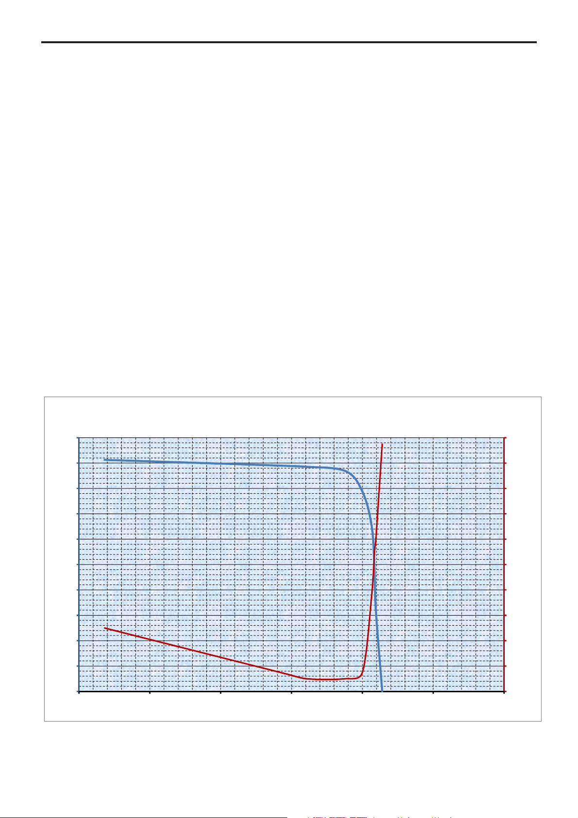
Pression acoustique à/Acoustic pressure at 1 m (dBA)
Débit Disponible B200 /Available B200 Flow rate ( m3/h)
Pression entrée CRV double/Double CRV inlet pressure (bar)
B200 Flow Control 20 bar : Débit et pression acoustique/Flow rate and acoustic pressure
Aspiration Compresseur/Compressor suction 1 atm 20°C
Mesure débit selon/ Flow measurement : ISO 5162-2
Mesure bruit/ Noise measurement : 1m de la CRV; 1.5 m du compresseur/ 1 m from the CRV; 1.m from the compressor

9/22
NT 1401-X00 10 18 B200 Flow Control e
2. GENERAL DATA (continued)
81,0
83,0
85,0
87,0
89,0
91,0
93,0
95,0
97,0
99,0
101,0
0
20
40
60
80
100
120
140
160
180
200
0,00 0,50 1,00 1,50 2,00 2,50 3,00
Pression acoustique à/Acoustic pressure at 1m(dBA)
Débit Disponible B200 /Available B200 Flow rate (m3/h)
Pression entrée CRV double/Double CRV inlet pressure (bar)
B200 Flow Control 2,3 bar : Débit et pression acoustique/Flow rate and acoustic pressure
Aspiration Compresseur/Compressor suction 1atm 20°C
Mesure débit selon/ Flow measurement :ISO 5162-2
Mesure bruit/ Noise measurement :1m de la CRV; 1.5 mdu compresseur/ 1mfrom the CRV; 1.m from the compressor
81,0
83,0
85,0
87,0
89,0
91,0
93,0
95,0
97,0
99,0
101,0
0
20
40
60
80
100
120
140
160
180
200
0,00 0,50 1,00 1,50 2,00 2,50 3,00
Pression acoustique à/Acoustic pressure at 1 m (dBA)
Débit Disponible B200 /Available B200 Flow rate ( m3/h)
Pression entrée CRV double/Double CRV inlet pressure (bar)
B200 Flow Control 2,5 bar : Débit et pression acoustique/Flow rate and acoustic pressure
Aspiration Compresseur/Compressor suction 1 atm 20°C
Mesure débit selon/ Flow measurement : ISO 5162-2
Mesure bruit/ Noise measurement : 1m de la CRV; 1.5 m du compresseur/ 1 m from the CRV; 1.m from the compressor

10/22
NT 1401-X00 10 18 B200 Flow Control e
3. INSTALLATION
3.1 B200 PF with truck power take-off
3.1.1 Installation of the compressor
The B200 PF compressors have a male splined shaft
DIN 5462 / ISO 14 and a mounting flange ISO 7653-D
that allows them to be installed directly on declutchable
power take-offs.
Power Take Off specifications :
• Must allow a gravity torque of 50 Nm and be able to
accept a working torque of 124 Nm along all the
unloading duration.
Tank builders :
• MERCEDES :
- Original model in aluminium type NA 131 2C com-
patible, in compliance with the dispensation delive-
red by MERCEDES.
- Every other model in cast iron or aluminium in
compliance with the specifications above.
• DAF / IVECO / MAN / RVI / SCANIA :
- Every original or not original model, whatever the
material : cast iron or aluminium, in compliance
with the specifications above.
• VOLVO :
- Original model in aluminium type PTR DM compa-
tible for the range FH/FM in compliance with the
dispensation delivered by VOLVO.
- Every other model in cast iron or aluminium in
compliance with the specifications above.
Not allowed :
• Power take off with double outlet
Installation and operating conditions :
• The use of the discharge flexible supplied by
MOUVEX, fitted in accordance with the B200
Instructions.
• The use of the fixation kit supplied by MOUVEX,
fitted in accordance with the B200 Instructions.
• No extra bracket required to fix the B200.
• B200 must be fitted, operated and serviced in a pro-
per installation in accordance with the B200
Instructions, with the PTO Manufacturer and Truck
Builder Instructions.
Installation is done with screws or studs, minimum grade
8.8.
The B200 PF is provided with a mounting kit that includes
a metallic PTO seal, and 4 specific nuts and washers
that it is essential to use.
If this is possible, tighten the 4 nuts to 37 Nm for all the
PTOs. Don’t put any grease on the studs.
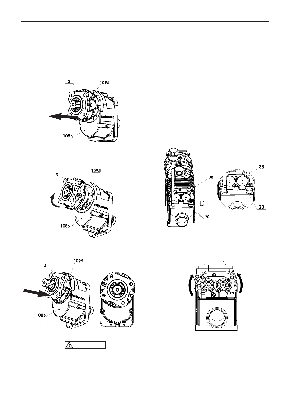
The compressor can be mounted in slightly tilted posi-
tion, but should remain within the angular values defined
on the figures below.
The tapped holes in step-up casing 1086 and the ope-
nings on cover 3can be used to obtain a suitable incli-
nation, whatever the inclination of the PTO flange.
To obtain only a slight inclination of the PTO flange, it is
possible to bring the compressor back in a horizontal
position, taking care to proceed as follows :
• Loosen the 8 screws 1095 without removing them.
• Put the compressor in the desired position.
• Tighten the screws 1095.
Initial position
WARNING
11/22
NT 1401-X00 10 18 B200 Flow Control e
To obtain a strong inclination of the PTO flange, it is pos-
sible to bring the inclination of the compressor to an
angle lower than 10°, taking care to proceed as follows
:
• Loosen and remove the 8 screws 1095.
• Remove the screws 1095 and the cover 3.
• Turn the cover 3in order to offset the ports and posi-
tion them over the next set of tapped holes on the
casing 1086.
• Engage the cover 3in the desired position.
• Tighten the 8 screws 1095.
Final position
Screws 1095 must be :
• equipped with their lock washers, notches on the
side of the screw head,
• sealed with Loctite®* thread locking 243 or equivalent,
• tightened at 13 Nm.
3.1.2 Adjustment of the drive speed
For compressors that are secured by flange on the power
take-off or on the hydraulic motor, the compressor drive
speed can only be measured indirectly on the male or
female screw of the compressor, using a tachometer
with a maximum capacity of 20 000 rpm.
A contact tachometer of the Multimetrix®RPM82 type is
perfectly well suited for measuring the speed on the
screws of the B200 compressor.
Since the male and female screws do not rotate at the
same speed, refer to the tables in the paragraphs below
in order to establish the correspondence between the
drive shaft speeds and the speed of the screw on which
the measurement is performed :
- Measure on the male screw : .......Table 1
- Measure on the female screw : ....Table 2
To access the rotating screws, unscrew screw 38 and
remove plugs 20.
In order to check that the compressor is rotating in
the right direction, check that the male and female
screws rotate in the directions specified on the dra-
wing below, whatever the drive variant (B200 12R
and B200 10L) :
The B200 compressors fitted with a check valve can
withstand a short operating time (less than 30 seconds)
in the opposite direction, as required for checking the
rotation direction.
NOTICE :
Prolonged operation in a direction different from the direc-
tion indicated on the drawing below may cause serious
damage to the compressor and would cancel the warranty.
CAUTION
3. INSTALLATION (continued)
* Loctite®is a registered trademark.

12/22
NT 1401-X00 10 18 B200 Flow Control e
Reversing the rotation direction requires that the com-
pressor be returned to the factory.
Speed pick-up on the male screw :
Table 1
Male screw and drive shaft speed correspondence
Speed pick-up on the female screw :
Table 2
Female screw and drive shaft speed correspondence
3.2 B200 PS with drive shaft
3.2.1 Installation of the compressor
• Mount the compressor in a position where it is protec-
ted from dirt, debris and road spray. The mounting
location should allow for regular inspection, cleaning
and maintenance.
• The B200 compressor mounting points are located on
the sides of the body.
Installation is performed by means of screws, minimum
grade 8.8.
3.2.2 Recommended drive conditions
The drive shaft must be sized so as to be able to accept
the loads above and also the starting torque.
Operating torque at full speed
It is the responsibility of the installer to check that his
design protects the transmission if the compressor blocks.
Compressors B200 12R PS and B200 10L PS must
be protected by a 400 Nm torque limiter, in order to
protect the truck's transmission if the compressor is
jammed. MOUVEX may not be held liable for any
damages resulting from such jamming if the torque
limiter has not been installed.
Comply strictly with the following instructions :
• The drive shaft slides perfectly well during rotation.
Square slip joints are forbidden.
• Drive shaft length should be as short as possible and
the drive shaft MUST be balanced.
Direction of rotation
Fixation points
Female
screw
Male screw
Inlet shaft speed
(rpm)
Female screw speed
(rpm)
B200 12R
850 11 600
1 000 13 640
1 100 15 000
1 200 16 365
B200 10L
700 11 450
800 13 095
900 14 730
1 000 16 365
Inlet shaft speed
(rpm)
Male screw speed
(rpm)
B200 12R
850 13 910
1 000 16 365
1 100 18 000
1 200 19 640
B200 10L
700 13 750
800 15 710
900 17 675
1 000 19 640
B200 Pressure
1,5 bar 2,0 bar 2,5 bar
Torque 12R (Nm) 83 93 103
Torque 10L (Nm) 100 111 124
WARNING
DRIVES SHAFTS MUST BE GUARDED
IF EXPOSED. OPERATION WITHOUT
GUARDS CAN CAUSE SERIOUS PER-
SONAL INJURY, MAJOR PROPERTY
DAMAGE OR DEATH.
Do not operate
without guard
in place.
3. INSTALLATION (continued)
13/22
NT 1401-X00 10 18 B200 Flow Control e
The non balancing of the drive shafts can lead to
mechanical ruptures that are susceptible of causing
important property damage and/or serious injuries.
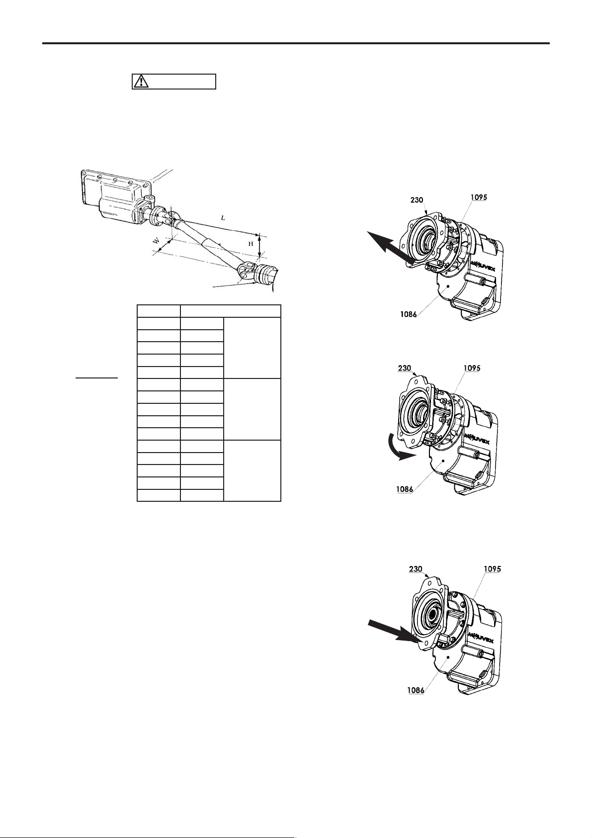
• The drive shaft and compressor shaft MUST be parallel
within 1° and have a maximum of 10°compound misali-
gnment. See Table :
• Universal joints MUST be in phase, with the drive shaft
slip joint at mid-position. Use an even number of uni-
versal joints.
• Make sure that the compressor rotates in the direction
of the arrow on the body.
The B200 compressors fitted with a check valve can
withstand a short operating time (less than 30
seconds) in the opposite direction, as required for
checking the rotation direction.
NOTICE :
Prolonged operation in a direction different from the
direction indicated on the drawing below may cause
serious damage to the compressor and would cancel the
warranty.
3.3 B200 HY with hydraulic motor
The B200 HY compressors have a female splined shaft
ANSI B92-1a that allows to flange directly on hydraulic
motor epuipped with a shaft 13T 718 SAE 16/32 and a
mounting flange SAE B 2 or 4 holes.
3.3.1 Hydraulic motor assembly
It is possible to change the orientation of the lantern 230,
taking care to proceed as follows :
• Loosen and remove the 8 screws 1095.
• Rotate the lantern 230 so as to offset the ports and
move them over the set of tapped holes on casing
1086 that approach the desired position.
• Make sure that at least one of the 2 collectors is loca-
ted in the lower part of the lantern 230, otherwise turn
the lantern 230 by 180°.
• Engage the lantern 230.
• Tighten the 8 screws 1095.
AUniversal joint angle
0,017 1°
VERY GOOD
0,035 2°
0,052 3°
0,070 4°
0,087 5°
0,105 6°
GOOD
0,125 7°
0,141 8°
0,158 9°
0,176 10°
0,194 11°
LIMIT
VALUES
0,213 12°
0,231 13°
0,249 14°
0,268 15°
_________
A = √H² + W²
L
If H = Zero, A = W / L
If W = Zero, A = H / L
CAUTION
3. INSTALLATION (continued)
14/22
NT 1401-X00 10 18 B200 Flow Control e
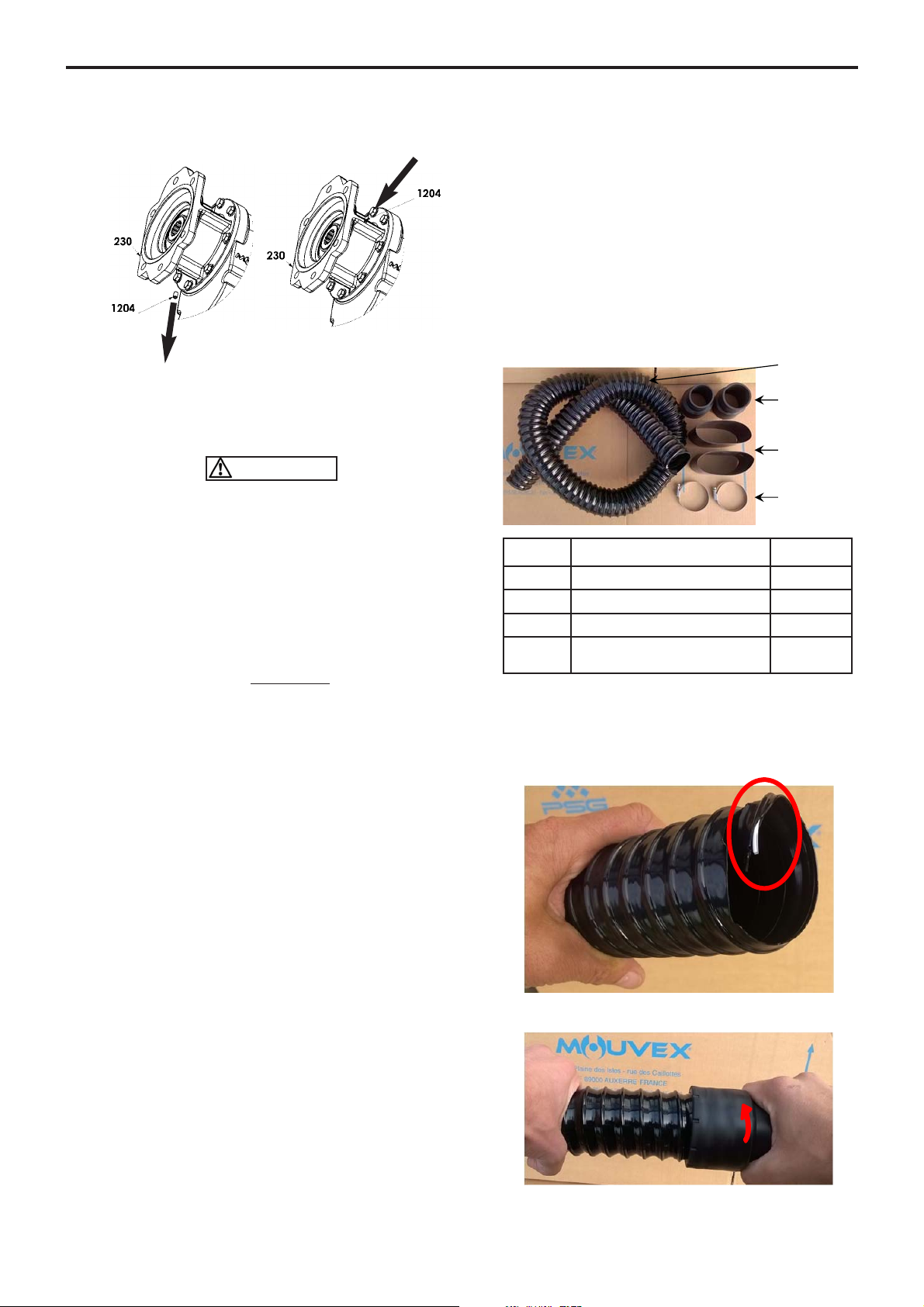
• Install the screwing plug 1204 in the highest collector
on the lantern 230.
• Check that the rotation direction of the motor and the
compressor are correct.
• Lubricate the motor shaft and the female splined shaft
1091 to facilitate subsequent disassembly.
Screws 1095 must be :
• equipped with their lock washers, notches on the
side of the screw head,
• sealed with Loctite®* thread locking 243 or equivalent,
• tightened at 13 Nm.
3.3.2 Adjustment of the drive speed
See § ADJUSTMENT OF THE DRIVE SPEED.
3.3.3 Motor management
The Motor management is mandatory, it has to ensure 2
missions :
• To secure the operating range : The operating point
(otherwise the range) must be set to avoid any ope-
ration outside the range. If a risk remains (need to
switch in complement a gear box button) an infor-
mation sticker shall be affixed in the cabin.
• To ensure a smooth start-up : The start-up of the
PTO must be carried out gradually without genera-
ting a peak of torque to avoid damaging the
Compressor. This is particularly sensitive for the
B200 PF which is equipped with a shaft groove.
It is in particular to ensure that the parameter
‘’TRANSMISSION INPUT SPEED’’ (N° 10.520 on
MERCEDES) is set to a value less than 10.
Otherwise, that will generate in a medium term a
breakage of the B200 shaft.
3.4 Piping
3.4.1 Inlet
The suction side of the compressor MUST be fitted with
an adequately sized air filter, which MUST be protected
from water, road spray, or other debris. This filter is avai-
lable from MOUVEX. Use of wrong filter will void warran-
ty. The compressor filter must be connected by means of
a hose capable of operating in vacuum and of a sufficient
length to absorb the relative movements of the compressor
relative to the chassis. The compressor is delivered with
an inlet connection kit which is installed as follows :
Composition of the kit :
Assembling procedure :
• To cut the hose to the length requested.
• To fold back the end of the wire inside.
• To screw home the humps at the 2 ends.
164
884
152A
165-166
Item Description Quantity
152A Heat shrinkable sleeve 2
164 Hose 1
165-166 Clamp 2
884 Hump 1XØ50
1XØ57
CAUTION
3. INSTALLATION (continued)
* Loctite®is a registered trademark.

• Result :
• To pass a heat-shrinkable sleeve on an end and to
center it on the end of the hump. To retract gradually by
means of a heat gun. Attention not to point the gun
towards the hose not covered, risk of perforation.
To proceed in the same way at the other end.
• To check the hose is perfectly clean inside, and to remove
the protections caps on the compressor.
• To assemble the unit on the compressor inlet port and
to tighten the clamp : cast solid end.
Example :
• To proceed in the same way with the air filter.
• To then suspend the hose while taking care to protect
it from any friction and the potentially hot bodies such
as muffler.
The inlet filter should be positioned to draw in clean, cool
air, and should be mounted away from any engine heat
and exhaust.
The compressor inlet suction air must be filtered in order
to eliminate particles bigger than 5 µm.
The maximum pressure drop at suction must be lower
than 75 mbar.
A restriction indicator system must permit changing the
suction filter when it creates a pressure drop greater
than 75 mbar.
The maximum acceptable temperature at suction as a
function of equipment operating conditions is given in
the § TECHNICAL CHARACTERISTICS.
3.4.2 Outlet
The flange supplied must be equipped with its gasket,
screw tightened at 44 Nm.
Piping MUST be at least as large as the compressor
suction and discharge connections.
All the connections located between the compressor and
the trailer hose connection point must be absolutely
waterproof. For that reason, they must be welded.
The B200 PF compressors directly flanged onto the
power take-off must be fitted with the metallic discharge
hose delivered with the equipment. This woven stainless
steel hose is designed to avoid having any stresses
applied on the compressor flange and the rigid pipes of
the systems, as induced by the relative movements of
the compressor with respect to the chassis.
For the B200 PF, it should cancel the stresses on the
flange, as induced by the movement of the compressor,
and respect the rules below :
• install a 90° elbow between the flange and the hose.
• support the stainless steel hose correctly at its end part.
• the hose output pins should be mounted in the same
horizontal plane. Make sure that the installation allows
a compressor displacement of ± 5 cm to be obtained.
• on the same horizontal plane, if the output pins are
not parallel, the bending radius must be as large as
possible, and in any case at least equal to 50 cm.
Make sure that the installation allows a compressor
displacement of ± 5 cm to be obtained.
==
5 cm
5 cm
15/22
NT 1401-X00 10 18 B200 Flow Control e
3. INSTALLATION (continued)

16/22
NT 1401-X00 10 18 B200 Flow Control e
Top view
Installation rules : Discharge line
All the connections must be welded and be the object
of a waterproof quality control.
During installation, position a pressure gage on the com-
pressor output, so as to measure the operating pressure.
The measurement should be done at the discharge flange
level and should not exceed 2,5 bar over the allowable
operating range of the compressor.
It is mandatory to protect the compressor with the Check
relief valve supplied by MOUVEX. The check valve pre-
vents any air from returning in the compressor when it is
no longer in operation.
The safety valve protects the compressor against possi-
ble overpressure. The maximum set point of the valve is
2,5 bar. If there is a drop in pressure between the pres-
sure relief valve and the compressor, reduce the pres-
sure relief valve setting by the value of the pressure
drop. It is the installor responsability to check that the
relief valve is compliant with the compressor performance
for the application speed.
The compressor is delivered with a check and relief valve
allowing 3 settings capabilities : 2 bar, 2,3 bar or 2,5 bar.
It will have to be selected depending of the installation limits
and by making sure the maximum pressure of 2,5 bar of
the compressor is never exceeded. Be careful in particular
with the pressure drop located between the check relief
valve and the compressor especially if an air cooler and
a silencer are used.
It is forbidden to insert a damping valve in the pipe lin-
king the compressor to the tank hose connector in order
to avoid any risk of water entering.
Ensure that ALL components are capable of operation at
the maximum system pressure limits and that all vessels
are adequately protected by SEPARATE relief valves.
3.4.3 Oil breather
Compressor B200 is fitted with an oil breather which is
mounted on a hose for easier installation.
In case of the inclination of the compressor, it is essen-
tial to position the breather on the highest tapped hole.
Invert the positions of the oil gage 399 and the breather
assembly, as appropriate.
Position the breather plug in a clear area, to avoid any oil
condensation.
Do not crush the hose when positioning the breather, so
as to allow any oil vapors to be evacuated.
The hose mustn’t be shortened,, keeps imperatively its
original length.
The breather must be placed above the compressor,
preferably with the connecting hose running up towards
the breather.
1
1
1111
1
1
CRV
Option
silencer
Hose (B200PF)
Oil breather
}
R mini 50 cm
WARNING
FAILURE TO INSTALL ADEQUATELY
SIZED PRESSURE RELIEF VALVE(S)
CAN CAUSE PROPERTY DAMAGE,
PERSONAL INJURY OR DEATH.
Hazardous pressure
can cause
personal injury
or property damage.
CAUTION
OPERATING A COMPRESSOR ABOVE
ITS MAXIMUM OPERATING PRESSURE
CAN CAUSE SUBSTANTIAL PROPERTY
DAMAGE OR SERIOUS BODILY INJU-
RIES.
Extreme heat can
cause injury or
property damage.
3. INSTALLATION (continued)

17/22
NT 1401-X00 10 18 B200 Flow Control e
4. USE OF COMPRESSOR
4.1 Lubricant recommendations
The MOUVEX screw compressor operates with MOUVEX
BSC2 oil.
It is imperative to change the BSC2 oil every year or 500
operation hours.
The BSC2 oil covers operation from -30°C to +40°C.
4.2 Filling of lubricant
Our compressors are delivered without oil. The use
of a compressor with an oil level different from 1,2 l
± 10% can lead to important property damage and
serious injuries.
Before starting the system, fill the casing with oil so that
the oil level is set between the min and max value of the
gauge.
4.3 Operation
• The compressor must be started with the discharge
valves open.
• The operator should remain nearby the equipment
throughout the use to ensure the proper functioning
of the system.
• Check the compressor drive shaft rotation direction :
- B200 12R PS and B200 10L PS : The drive shaft
rotation direction must match with the arrow on the
body of the compressor.
- B200 12R PF and B200 10L PF : Refer to § DIRECT
INSTALLATION TRUCK POWER TAKE-OFF.
4.3.3 Start-up procedure for manual gear box
• Start the engine and run with standard speed.
• Depress clutch and engage the PTO.
• Release the clutch SLOWLY.
• Set engine speed to give the correct compressor speed.
4.3.4 Shutting down procedure for manual gear
box
• Depress the clutch and disengage the PTO.
• Reduce engine speed to idle.
ALWAYS DISENGAGE THE DRIVE BEFORE SLOWING ENGINE
DOWN.
• Release the clutch.
NOTICE :
Prolonged operation in a direction other than the
direction of the arrow on the body can cause serious
damages to the compressor and would cancel the
warranty.
• Avoid if possible stopping or starting the compressor
with the tank under pressure.
• At commissioning, check that the combinations of
rotation speed and discharge pressure of the com-
pressors are in conformity with those indicated in §
TECHNICAL CHARACTERISTICS.
During operation, the temperature of the surface of
a compressor and nearby parts can be in the region
of 200°C. The compressor and the parts located
nearby are thus susceptible of provoking serious
burns and property damage. Be careful to not
approach elements that are sensitive to heat and
affix plates informing users that the compressor is
hot, to prevent any risk of burns.
PTO
ON SLOWLY
PTO
OFF
CAUTION
CAUTION CAUTION
18/22
NT 1401-X00 10 18 B200 Flow Control e
5. MAINTENANCE
5.1 Maintenance schedules
After every cleaning of the truck
Always run the compressor for 15 minutes to remove
any water that inadvertently gets into the piping. DO
NOT fog or introduce anti-corrosive liquids into the com-
pressor to prevent corrosion : Use of liquids in the com-
pressor will cause failure.
Weekly
1. The compressor should be run for at least 15 minutes
to prevent moisture from collecting inside. This will
reduce the risk of corrosion damage to the compres-
sor and other equipment in the piping.
2. Inspect and clean air filter. Inspect DAILY if operating
in dirty or severe environment. Check the condition of
the inlet filter hose for splits and tears. Replace or
repair as necessary.
3. Inspect compressor, system piping and components.
Clean or repair as necessary.
4. Check power transmission line.
5. Check the air filter restriction indicator. When the indica-
tor turns red, replace the filter cartridge. Before repla-
cing the cartridge with a new one, clean the inside of
the filter's body with a clean damp cloth.
Per manufacturer’ s recommendations
Lubricate the universal seal (for B200 PS models).
Monthly
1. Check the relief valve(s) for wear and proper settings.
Replace or adjust as necessary.
2. Check that the check valve works properly, replace as
necessary.
3. Check the oil level and complete if necessary.
Yearly :
1. Check tightness of the 4 mounting nuts on the B200 PTO.
5.2 Compressor oil change
Oil recommendations : See § LUBRICANT RECOMMEN-
DATIONS.
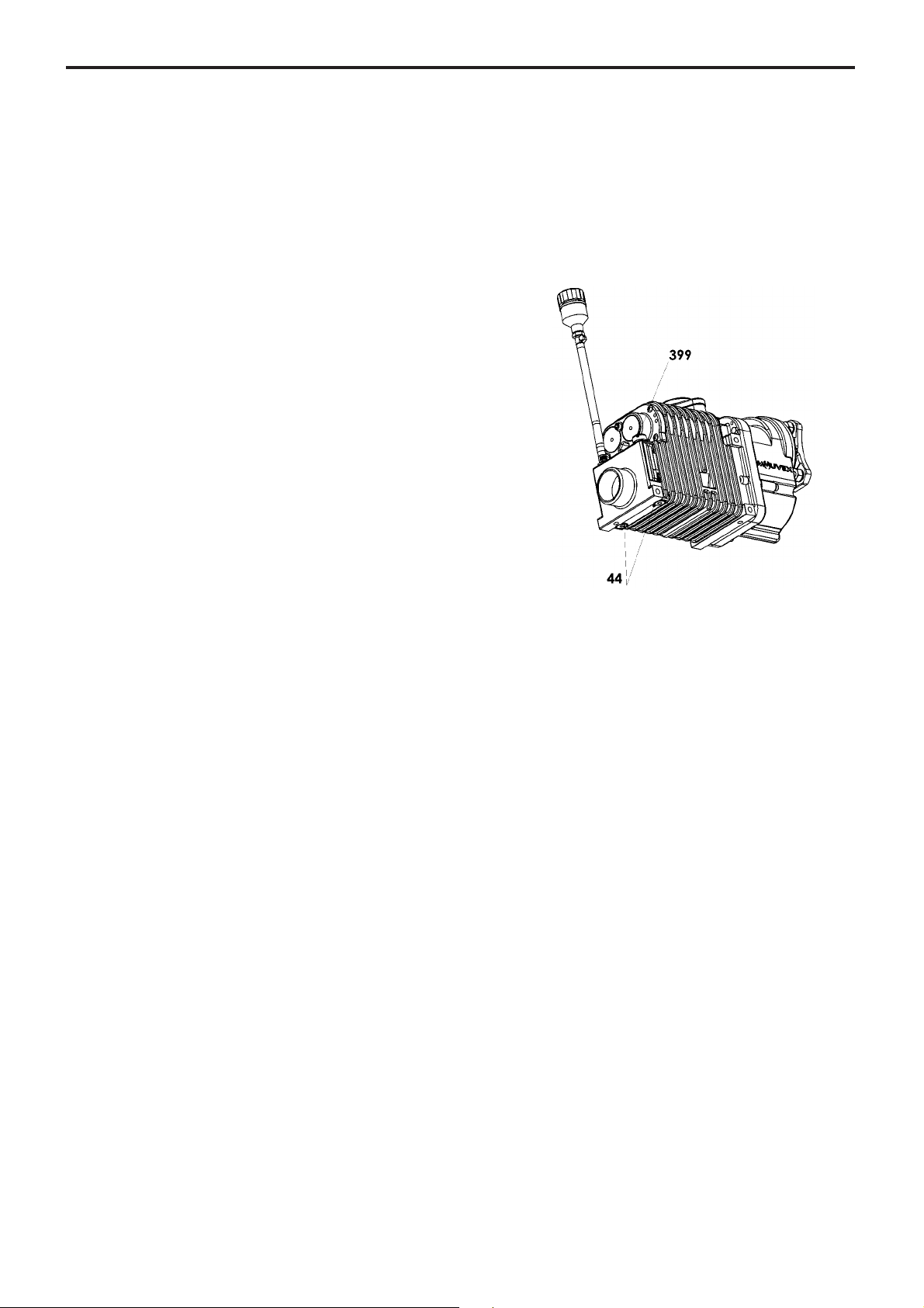
Depending on the inclination of the compressor, remove
the lowest drain plug 44.
Put plug 44 back into place and remove filling plug 399
and fill the compressor with new oil, as recommended in
§ LUBRICANT RECOMMENDATIONS.
19/22
NT 1401-X00 10 18 B200 Flow Control e
5. MAINTENANCE (continued)
5.3 Inlet shaft replacement
The B200 PF inlet shaft has a groove that breaks the
shaft in case of excess torque, as required to protect the
gear box and the PTO.
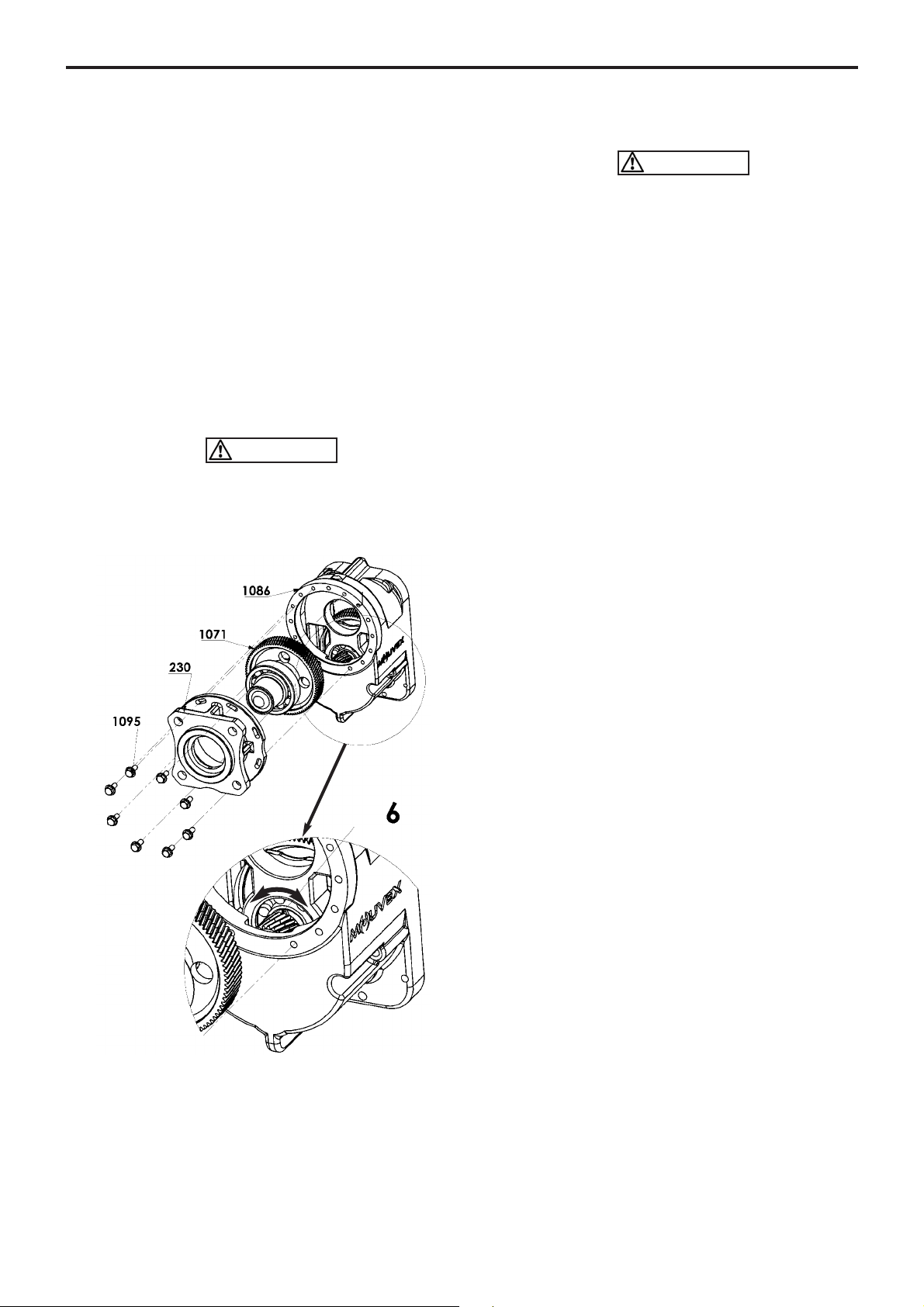
Before replacing the inlet shaft, it is essential to make sure
that the compressor is not damaged :
• Loosen and remove the 8 screws 1095.
• Remove the wheel, complete with the remaining part
of the shaft.
• Rotate the wheel 6 manually and check that it can
rotate freely and without any hard point over a com-
plete rotation.
• Inspect the screws on the discharge part and make
sure that there are not any marks of contact between
the screws, or due to the presence of any foreign
bodies.
The compressor is to replace if :
• wheel 6does not rotate.
• wheel 6cannot rotate easily.
• marks can be seen on the screws.
• Engage the bearing of shaft kit 1071 in the housing of
casing 1086.
• Check the state of the lip seals 1089 and the O’ring
40. Make sure that they are not damaged.
• Engage the lantern 230 in the desired position.
• Tighten the 8 screws 1095.
For the installation of the compressor on the power take-
off, refer to § DIRECT INSTALLATION ON B200 PF TRUCK
POWER TAKE-OFF.
Screws 1095 must be :
• equipped with their lock washers, notches on the
side of the screw head,
• sealed with Loctite®* thread locking 243 or equivalent,
• tightened at 13 Nm.
5.4 Warranty claims
The compressor oil is considered as wear part.
No failure connected with wear part damage will be
accepted under warranty conditions.
The following situations will void warranty for all compo-
nents of the compressor :
• Installation not in accordance with the CL 1401-001
Control check list installation B200 FC.
• No MOUVEX Check relief valve.
• Tampering with the setting of the relief valve.
• Presence of foreign body inside the compressor body.
• Traces of damage representative of abnormal use of
the compressor.
• Use of non genuine parts.
• If the compressor is repaired by a repairer who is not
a MOUVEX-approved repairer.
• Construction of the package not validated by our
Design Office.
• Use of an oil other than BSC2.
• Presence of a dumping valve on the pipe linking the
compressor to the tank hose connector.
• Motor management not fixed, allowing the operator a
using outside the working range.
Before returning your equipment to the factory, you must
first obtain an Equipment return approval (RMA) from our
After Sales Department.
A Compressors form information shall be filled by the
installer or distributor and send to MOUVEX in order to
claim for a warranty.
WARNING
CAUTION
* Loctite®is a registered trademark.

20/22
NT 1401-X00 10 18 B200 Flow Control e
7.1 Compressor
The equipment must be systematically stored in an area
sheltered from bad weather.
The equipment must bear its original protective compo-
nents until it is installed in its final application.
If installation is interrupted, put back in place the original
protective components or equivalent components.
7.2 BSC2 oil
In its unopened original container in a dry, frost-free and
light-free place.
The maximum shelf life is approx. 60 months.
7. STORAGE CONDITIONS
The compressor must be scrapped in compliance with the
regulations in force.
During this operation, particular care must be paid to the drai-
nage stages of the compressor.
8. SCRAPPING
Problem Possible origin Possible solution
1. Pressure issue
Too much pressure drop. Tocheck pipes diameter.
Relief valvedamaged. Tocheck the opening point.
Noreturn valvedamaged. Tocheck the proper operating of the Noreturn
valve.
2. Flow rate issue
Wrong Compressor speed. Toadjust the speed by taking care of the range
allowed.
Relief valvedamaged. Tocheck the opening point.
3.Abnormal hightemperature
Air filter clogged. Toclean the cartridgeor to replace it.
Air pressure too much high. Tosee problems 1. /2.
Outside temperature too much high. Torespect the maximum external temperature
allowed.
Lack of oil. Tocheck the oil level.
Compressor speed too much low.Toadjust the speed by taking care of the range
allowed.
4. Inlet pressure drop > 75mbar
(Clogging indicator red)
Air filter clogged. Toclean the cartridgeor to replace it.
Air inlet hose folded. Tocheck the air inlet hose.
5. Compressor doesn’toperate
Torque limiter damaged. Toreplace the torque limiter.
Transmission damaged. Toconsult your Service point.
6. Torque limiter damaged
Screw Compressor damaged. Toconsult your Service point.
Wrong motor /transmission management. Toconsult your Truck dealer.
Oil too much viscous. Tobe in compliance with the MOUVEX
Instructions.
7.Oil leak
Too much oil. Tocheck the oil level.
Oil breather clogged. Toclean the oil breather.
8. Vibrations
Wrong motor speed. Toincrease the speed by taking care of the
rangeallowed.
Transmission damaged. Tocheck the driving shaft.
Lack of rigidity of the chassis. Tobe in compliance with the Truck
Manufacturer Instructions.
6. TROUBLESHOOTING
CAUTION :
OBSERVE ALL SAFETY WARNINGS CONTAINED IN THIS MANUAL.
Table of contents
Popular Air Compressor manuals by other brands


Certa
Certa CTAICOMWISA quick start guide

Iwata
Iwata Silver JET IS50 Operating instructions manual

Parkside
Parkside PKO 270 A1 Operating and safety instructions

Black & Decker
Black & Decker 641915-00 instruction manual

California Air Tools
California Air Tools 20040DC owner's manual

EINHELL
EINHELL EURO 4000/1 operating instructions


