PSI Woodworking Products GRIND3X User manual

#GRIND3X MANUAL PSI Woodworking Products
8” Variable Speed Bench Grinder
CAUTION
Read and Understand this manual before assembling and operating this grinder
THIS SYMBOL DESIGNATES THAT THIS TOOL IS LISTED BY THE INTERTEK
TESTING SERVICES, TO UNITED STATES AND CANADIAN STANDARDS
8” Variable Speed Bench Grinder
Distributed by © 2017 PSI Woodworking • Philadelphia, PA 19115
Manufactured by: Penn State Industries
C US
226002
C
US

#GRIND3X MANUAL PSI Woodworking Products
1. KEEP GUARDS IN PLACE and in working order.
2. KEEP WORK AREA CLEAN. Cluttered areas and benches invite
accidents.
3. DON’T USE IN DANGEROUS ENVIRONMENT. Don’t use power
tools in damp or wet locations, or expose them to rain. Keep work
area well lighted.
4. KEEP CHILDREN AWAY. All visitors should be kept safe distance
from work area.
5. MAKE WORKSHOP KID PROOF removing starter keys.
6. DON’T FORCE TOOL. It will do the job better and safer at the rate
for which it was designed.
7. USE RIGHT TOOL. Don’t force tool or attachment to do a job for
which it was not designed.
8. USE PROPER EXTENSION CORD. Make sure your extension cord
is in good condition. When using an extension cord, be sure to use
one heavy enough to carry the current your product will draw. An
undersized cord will cause a drop in line voltage resulting in loss of
power and overheating. Table shows the correct size to use
depending on cord length and nameplate ampere rating. If in doubt,
use the next heavier gage. The smaller the gage number, the
heavier the cord.
SPECIFIC SAFETY RULES FOR WOOD LATHES
WARNING - No adjustment should be made until the tool has been
stopped.
WARNING - Risk of injury due to accidental starting. Do not use in an
area where children may be present.
WARNING For Your Own Safety Read Instruction Manual Before
Operating Lathe.
a) Wear eye protection.
b) Do not wear gloves, necktie, or loose clothing.
c) Tighten all locks before operating.
d) Rotate workpiece by hand before applying power.
e) Rough out workpiece before installing on faceplate.
f) Do not mount split workpiece or one containing knot.
g) Use lowest speed when starting new workpiece.
WARNING: DO NOT EXPOSE TO RAIN OR USE IN DAMP
LOCATIONS.
ADDITIONAL SAFETY RULES FOR WOOD LATHES
1. Do not allow the turning tools to bite into the wood. The wood could
split or be thrown from the lathe.
2. Always position the tool rest above the centreline of the lathe when
shaping a piece of stock.
3. Do not operate the lathe if it is rotating in the wrong direction.
The workpiece must always be rotating toward you.
4. Before attaching a workpiece to the faceplate, always rough it out to
make it as round as possible, this minimizes the vibrations while the
piece is being turned. Always fasten the workpiece securely to the
faceplate, failure to do this could result in the workpiece being
thrown away from the lathe.
5. Position your hands so that they will not slip onto the workpiece.
9. WEAR PROPER APPAREL. Do not wear loose clothing, gloves,
neckties, rings, bracelets, or other jewelry which may get caught in
moving parts. Nonslip footwear is recommended. Wear protective
hair covering to contain long hair.
10. ALWAYS USE SAFETY GLASSES. Also use face or dust mask if
cutting operation is dusty. Everyday eyeglasses only have impact
resistant lenses, they are NOT safety glasses.
11. DON’T OVERREACH. Keep proper footing and balance at all
times.
12. MAINTAIN TOOLS WITH CARE. Keep tools sharp and clean for
best and safest performance. Follow instructions for lubricating and
changing accessories.
13. DISCONNECT TOOLS before servicing; when changing
accessories, such as blades, bits, cutters, and the like.
14. REDUCE THE RISK OF UNINTENTIONAL STARTING. Make sure
switch is in off position before plugging in.
15. USE RECOMMENDED ACCESSORIES. Consult the owner’s
manual for recommended accessories. The use of improper
accessories may cause risk of injury to persons.
16. NEVER STAND ON TOOL. Serious injury could occur if the tool is
tipped or if the cutting tool is unintentionally contacted.
17. CHECK DAMAGED PARTS.Before further use of the tool, a guard
or other part that is damaged should be carefully checked to
determine that it will operate properly and perform its intended
function – check for alignment of moving parts, binding of moving
parts, breakage of parts, mounting, and any other conditions that
may affect its operation. A guard or other part that is damaged
should be properly repaired or replaced.
18. NEVER LEAVE TOOL RUNNING UNATTENDED. TURN POWER
OFF. Don’t leave tool until it comes to a complete stop.
GENERAL & SPECIFIC
SAFETY RULES
2
GRINDER SAFETY RULES
1. Always use guards and eye shields. Always wear safety glasses or eye protection when operating this tool and keep the eye
shields mounted in their proper position on the wheel guard.
2. Replace a cracked wheel immediately. Handle wheels carefully to avoid bumping or dropping. DO NOT use a grinding wheel
that has been dropped. Before use, inspect each wheel for cracks or aws. If cracks are evident, discard the wheel.
3. Before mounting a new wheel, be sure that it is marked with a RPM. that is the same as, or higher than the no load speed of
the grinder as marked on the nameplate.
4. Never start a grinder with anyone, including the operator, standing in line with the wheel. After installing a replacement wheel,
stand to one side and allow it to run for about one minute.
5. Do not grind on the sides of grinding wheels unless they are the special wheels designed specically for this purpose.
6. Do not over tighten wheel nut.
7. Use only anges furnished with this grinder.
8. CHECK DAMAGED PARTS. Before further use of the tool, a guard of other part that is damaged should be carefully
checked to assure that it will operate properly and perform its intended function; check for alignment of moving parts, binding
of moving parts, breakage of parts, mounting, and any other conditions that may aect it’s operation. A guard of other part that
is damaged should be properly repaired or replaced.
9. Bolt bench grinder to a bench of pedestal to prevent movement.
10. Use any accessory only in the proper and intended manner.
1. KEEP GUARDS IN PLACE and in working order.
2. KEEP WORK AREA CLEAN. Cluttered areas and benches
invite accidents.
3. DON’T USE IN DANGEROUS ENVIRONMENT. Don’t use
power tools in damp or wet locations, or expose them to rain.
Keep work area well lighted.
4. KEEP CHILDREN AWAY. All visitors should be kept safe
distance away from work area.
5. MAKE WORKSHOP KID PROOF removing starter keys.
6. DON’T FORCE TOOL. It will do the job better and safer at
the rate for which it is designed.
7. USE PROPER EXTENSION CORD. Make sure your exten-
sion cord is in good condition. When using an extension cord,
be sure to use one heavy enough to carry the current your
product will draw. An undersized cord will cause a drop in
line voltage resulting in loss of power and overheating. Table
shows the correct size to use depending on cord length and
name plate ampere rating. If in doubt, use the next heavier
gauge.
8 . WEAR PROPER APPAREL. Do not wear loose clothing,
gloves, neckties, rings, bracelets, or other jewelery which may
get caught in moving parts. Nonslip footwear is recommend-
ed. wear protective hair covering to contain long hair.
9. ALWAYS USE SAFETY GLASSES. Also use face or dust
mask if cutting operation is dusty. Everyday eyeglasses only
have impact resistent lenses, they are NOT saftey glasses.
10. DISCONNECT TOOLS before servicing; when changing
accessories, such as blades, bits, cutters, and the like.
11. REDUCE THE RISK OF UNINTENTIONAL STARTING.
Make sure switch is in o position before plugging in.
12. USE INCLUDED ACCESSORIES. Consult the owner’s
manual for included accessories. The use of 3rd party acces-
sories may cause risk of injury to persons.
13. CHECK DAMAGED PARTS. Before further use of the
tool, a guard or other part that is damaged should be carefully
checked to determine that it will operate properly and perform
its intended function - check for alignment of moving parts,
binding of moving parts, breakage of parts, mounting, and
any other conditions that may aect its operation. A part that
is damaged should be properly repaired or replaced.
14. NEVER LEAVE TOOL RUNNING UNATTENDED. TURN
YOUR POWER OFF. Don’t leave tool until it comes to a com-
plete stop.
Ampere Rating
More Than
*GRIND3X Rating
5* 18*
10 16* 14* 12*
10 16
12 16 14 12
120 V 25 ft 50 ft 100 ft
AWG Wire Gauge
150 ft
12 14
16 12
Not More Than
Not Reccommended
Volts Total length of cord in feet
2

THIS TOOL MUST BE GROUNDED WHILE IN USE TO PROTECT THE OPERATOR FROM ELECTRIC SHOCK.
IN THE EVENT OF A MALFUNCTION OR BREAKDOWN, grounding provides the path of least resistance for electric
current and reduces the risk of electric shock. This tool is equipped with an electric cord that has
an equipment grounding conductor and a grounding plug. The plug MUST be plugged into a matching electrical recep-
tacle that is properly installed and grounded in accordance with ALL local codes and ordinances.
DO NOT MODIFY THE PLUG PROVIDED.
If it will not t the electrical receptacle, have the proper electrical receptacle installed by a qualied electrician.
IMPROPER ELECTRICAL CONNECTION of the equipment grounding conductor can result in risk of electric shock. The
conductor with the green insulation (with or without yellow stripes) is the equipment grounding conductor. DO NOT con-
nect the equipment grounding conductor to a live terminal if repair or replacement of the electric cord or plug is neces-
sary. CHECK with a qualied electrician or service personnel if you do not completely understand the grounding instruc-
tions, or if you are not sure the tool is properly grounded.
USE ONLY A 3-WIRE EXTENSION CORD THAT HAS A 3-PRONG GROUNDING PLUG AND A 3-POLE RECEPTACLE
THAT ACCEPTS THE TOOL’S PLUG. REPLACE A DAMAGED OR WORN CORD IMMEDIATELY.
This tool is intended for use on a circuit that has an electrical receptacle as shown in Left Figure. Shows a 3-wire elec-
trical plug and electrical receptacle that has a grounding conductor. If a properly grounded electrical receptacle is not
available, anadapter as shown in Right Figure can be used to temporarily connect this plug to a 2-contact ungrounded
receptacle. The adapter has a rigid lug extending from it that MUST be connected to a permanent earth ground, such as
a properly grounded receptacle box. THIS ADAPTER IS PROHIBITED IN CANADA.
WARNING
To assure that no damage has been done to this unit during shipment, move the grinding wheel manually before electri-
caly running this unit.
If the grinding wheel does NOT spin freely, check this operation manual to make proper adjustments.
3
WARRANTY
This Grinder is warranted against defects in materials and workmanship for a period of two (2) years from the date of pur-
chase. This warranty applies to the purchaser of this product, and is limited to repair or replacement of the product or it’s
parts at PSI Woodworking Products’ discretion. Excluded are parts, which have been misused, abused, altered, or con-
sumed by normal operation of the machine. Also excluded are direct or consequential damages to the persons, property,
and/or materials. Your invoice serves as proof of purchase and must be referenced prior to return authorization. Contact
your dealer where you purchased your grinder for service or repair issues.

MOTOR POWER 3/4HP, 120v, 5a, 60Hz
MOTOR RPM 2000 to 3400 RPM (variable)
GRINDING WHEEL SIZE 8” x 1”, 5/8” Bore
GRINDING WHEEL GRIT 120 Grit (White) & 60 Grit (Grey)
LAMP 120v, 40 Watt or Less
SPARKS ARRESTORS Left and Right
EYE SHIELDS Clear Plastic, Left and Right
TOOL RESTS Left and Right
QUENCH TRAY 3.4” W x 2.8” L x .63” D
SPECIFICATIONS
CARTON CONTENTS
The following items are provided in parts bag inside
the the shipping box:
Grinder (not shown)
A. Eyeshield assembly, left
B. Eyeshield assembly, right
D. Tool rest support, right
E. Tool rest support, left
F. Carriage bolt M6 x 12 (2)
G. Spark arrestor, left
H. Spark arrestor, right
I. Tool rest, left
J. Tool rest, right
K. Pan head screws w/ washers M5 x 10 (4)
L. Eyeshield knob (2)
M. Tool rest knob (2)
N. Flat Washer M6 (4)
Light Bulb (not shown)
4
AB
D E F
G
H
IJ
K
L
M
N
COMPONENTS
A
T1
I
MP
Q
R
D
J
S
T2
B
U
V
8” BENCH GRINDER OVERVIEW
A. Eyeshield Assembly, Left
B. Eyeshield Assembly, Right
I. Tool Rest Left
J. Toolrest Right
M. Tool Rest Adjustment Knobs
O. 8” Grinding Wheel 120 grit
P. Variable Speed Dial
Q. Switch Key
R. Quench Tray
S. Wheel Cover
T1. 8” Grinding Wheel 120 Grit
T2. 8” Grinding Wheel 60 Grit
U. Gooseneck Lamp
V. Motor
W. Switch Assembly (Not Shown)
X. Capacitor (Not Shown)
PARTS KEY:
ZGR3X-01 (A - M) Parts Bag
ZGR3X-02 (P + Q + W) Switch Assembly
ZGR3X-03 (Q) Switch Key
ZGR3X-04 (X) Capacitor
5
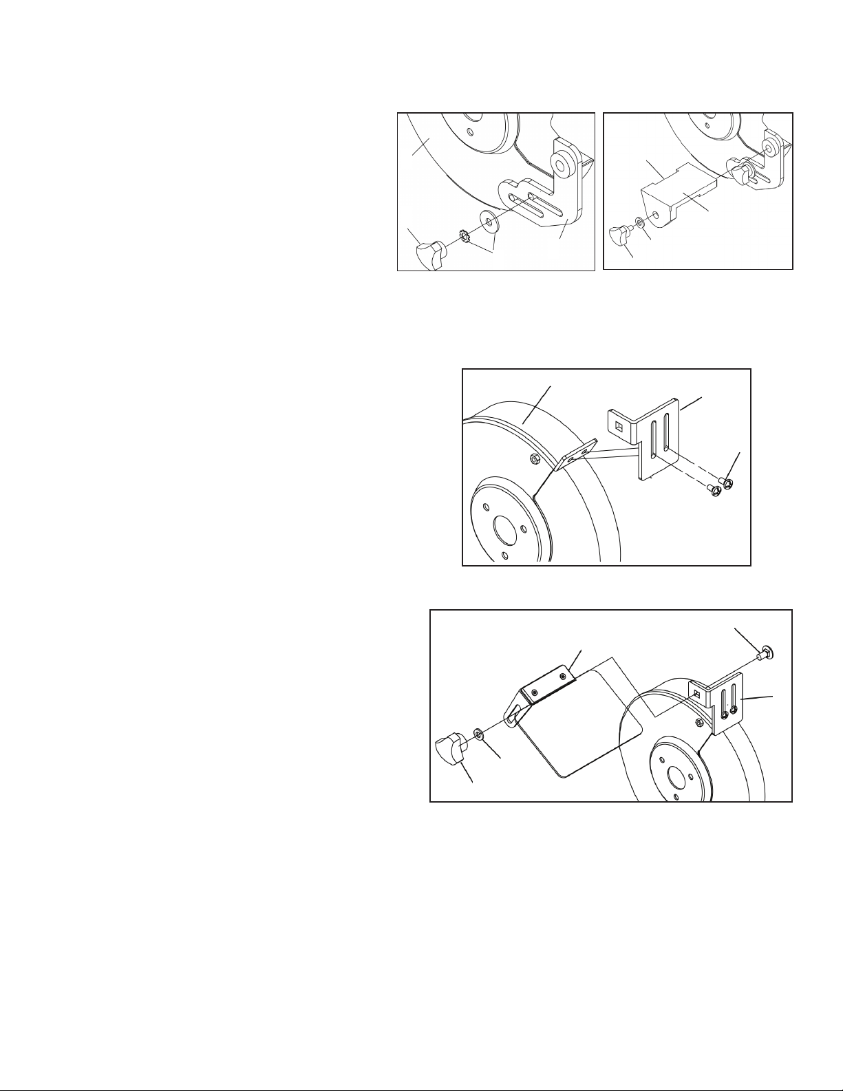
TOOL RESTS (Figs. A and B)
The Bench Grinder is provided with two dierent Tool
Rests assemblies. The Left Side Tool Rest is grooved
to accept drill bits. The Right Side Tool Rest is entirely
at.
1. Assemble the Tool Rest Supports (D,E) to the inside
surface of the Wheel Covers (S) with the at and lock
washers (N) and knobs (M) as shown.
2. Assemble the Tool Rests (I,J) to the Supports (D,E)
with the at washers (N) and Adjustment Knobs (M) as
shown. See Figure B.
3. Adjust each Tool Rest until its inside edge is 1/16”
from the grinding wheel. Firmly tighten the knobs hold-
ing the supports.
SPARK ARRESTORS (Fig. C)
1. Assemble the Spark Arrestors (G,H) to the front sur-
face of the Wheel Covers (S) with the at washers and
pan head screws (K) as shown. See Figure C.
2. Adjust each Spark Arrestor until the lower edge is
1/16” from the grinding wheel. Firmly tighten the hex
head screws.
ASSEMBLY INSTRUCTIONS
WORK LIGHT
The Bench Grinder is provided with a Flexible Work Light (U)
to assist in visibility of the workpiece. Accepts 40watt bulb
PERMANENT MOUNTING
Use the mounting pads on the base of the grinder to
rmly attach grinder to a solid work surface (hardware not
included).
Fig. B
Fig. C - Spark Arrestors
Fig. D - Eye Sheilds
Fig. A
EYESHIELDS (Fig. D)
1. Assemble the eyeshield (A,B) to the mounted Spark Ar-
restors (G,H) inserting carriage head screw (F) through the
Spark Arrestor and the Eyeshield as shown.
2. Assemble the at washer (N) and Lock Knob (L) to the
carriage head screw and tighten until the Eyeshield remains
in the desired position.
S
M
D
N
S
L
N
A
F
H
K
MN
J
H
H

6
When you face the bench grinder, the wheel on your left is a 120 grit grinding wheel. The wheel to your right (J) is a 60
grit grinding wheel. These wheels are used for grinding wood and plastic, removing paint and rust, polishing metal, hon-
ing cutting tools, smoothing rough edges on glass, sheet metal, etc.
To operate the bench grinder, put of safety glasses or other eye protection and hold the work rmly. Rest the work on the
tool rest and feed it slowly into the wheel at the desired grinding angle. Treat the wheel with respect, never jam work into
the wheel or use unnecessary pressure.
Grind only on the face of the grinding wheel, unless you have special wheels specically made to permit grinding on the
side of the wheel. This bench grinder is equipped with two grinding wheels.
Before Starting
1. The Power Switch must be in the “OFF” position and the Variable Speed Switch must be turned to its slowest setting
by being turned all the way to the left until solid resistance is felt.
2. Stand to the side of the Bench Grinder and plug in the power cord to a suitable power source.
3. Remain to the side of the Bench Grinder and turn it “ON” by moving the power switch to the up position.
4. Allow the grinding wheels to come up to a steady speed for at least one minute. The R.P.M.’s of the Bench Grinder
can be now increased to the desired speed for the particular grinding operation by rotating the Variable Speed Switch
clockwise.
5. Adjust the eyeshields. Place the workpiece on the appropriate tool rest for the desired operation.
6. Move the workpiece towards the grinding wheel until it lightly touches. Move
the workpiece back and forth across the front surface of the grinding wheel removing the amount of material desired.
To avoid serious injury, never grind on the sides of the grinding wheels.
7. To use the Drill Bit Sharpening tool rest, lay the drill bit at in the “V” groove. Firmly hold on to the drill bit shank. Slide
the drill bit towards the grinding wheel unit until it lightly touches. Keep the drill bit at to the plate and rotate the drill bit.
8. The operator may place the hot end of the workpiece into the water in the quench tray to cool it.
9. After completing the grinding operations, turn “OFF” the Bench Grinder by pushing down on the Power Switch.
It will take a few minutes for the grinding wheels to come to a complete stop.
10. Turn the Variable Speed Switch counterclockwise to return it to its slowest setting.
If used, the Flexible Work Light housing will remain hot for a few minutes after turning it “OFF”. Avoid contact with hous-
ing until it is cool.
11. Unplug the Bench Grinder from the power source. NOTE: To prevent unauthorized use of the Bench Grinder, the
power switch has a removable locking key. With the power switch in the “OFF” position, pull the locking key out. The
Bench Grinder cannot be turned “ON” with the key removed. Insert the locking key to resume grinding operations.
OPERATING INSTRUCTIONS
GRINDING SPEED CHART
CHANGING THE GRINDING WHEEL (Fig. K)
Due to normal wear, both wheels will need to be replaced occasionally.
1. Turn the power switch OFF and unplug the power cord from its power source.
2. Rotate the eyeshield up to access the tool rest.
3. Loosen the tool rest knob and rotate the tool rest away from the grinding wheel.
4. Remove the Wheel Cover (B).
5. Push a wood wedge between the grinding wheel and the guard. Then use a cresent wrench to remove the arbor hex
nut.
Low Speed 1745 RPM
Light Duty Operations
High Speed 3450 RPM
Heavy Duty/Normal Operations
Light Grinding Heavy Grinding
Chisel Sharpening Stock Removal
Rust and paint removal Deburring
Lowered grinding temperature Bung

6. NOTE: The left hand arbor hex nut (E) is left hand threaded and is
loosened by rotating it clockwise. The right hand arbor hex nut is right
hand threaded and is loosened by rotating it counter-clockwise.
7. Remove the Outer Wheel Flange (H) and then the abrasive wheel (I)
from the arbor shaft.
8. The new abrasive wheel to be put onto the grind-
er must have a higher R.P.M. rating than the grinder (3450 R.P.M.). The
new abrasive wheel must have the correct outer wheel diameter and
bore diameter as original wheels. The label on the side of the abrasive
wheel must stay on. DO NOT remove this label.
9. Replace the abrasive wheel, outer wheel ange and arbor hex nut.
NOTE: The left hand arbor hex nut is left hand threaded and is tightened
by rotating it counter-clockwise. The right hand arbor hex nut is right
hand threaded and is tightened by rotating it clockwise.
DO NOT OVER TIGHTEN the arbor hex nut as this may damage the
abrasive wheel and cause serious injury to the operator.
Fig. K
Follow the same procedure for replacing
the right wheel.
7
TO PREVENT INJURY TO YOURSELF or damage to the Bench Grinder, turn the switch to the
“OFF” position and unplug the power cord from the electrical receptacle before making any
adjustments.
TROUBLESHOOTING

Distributed by © 2017 PSI Woodworking • Philadelphia, PA 19115
Manufactured by: Penn State Industries
Table of contents
Popular Grinder manuals by other brands

Felisatti
Felisatti AF 180/1800S operating instructions

Cuisinart
Cuisinart SG-10A INSTRUCTION AND RECIPE BOOKLET

Ryobi
Ryobi R18AG-0 Original instructions

Bort
Bort BWS-600N user manual

Clarke
Clarke CBG6RL Operating and maintenance instructions

Parkside
Parkside PFBS 12 A1 Translation of the original instructions


