Pump House PH-0.8L-HL User manual

PH-0.8L-HL
Boiler Condensate Pump
Installation Instructions
Pump House
Glaisdale Drive East
Nottingham
NG8 4LY
Tel: 0115 900 5858
www.pumph.co.uk

PH-0.8L-HL Installation Instructions
1
For further installation advice please call the technical support helpline on 0115 900 5858.
SPECIFICATIONPH-0.8L-HL
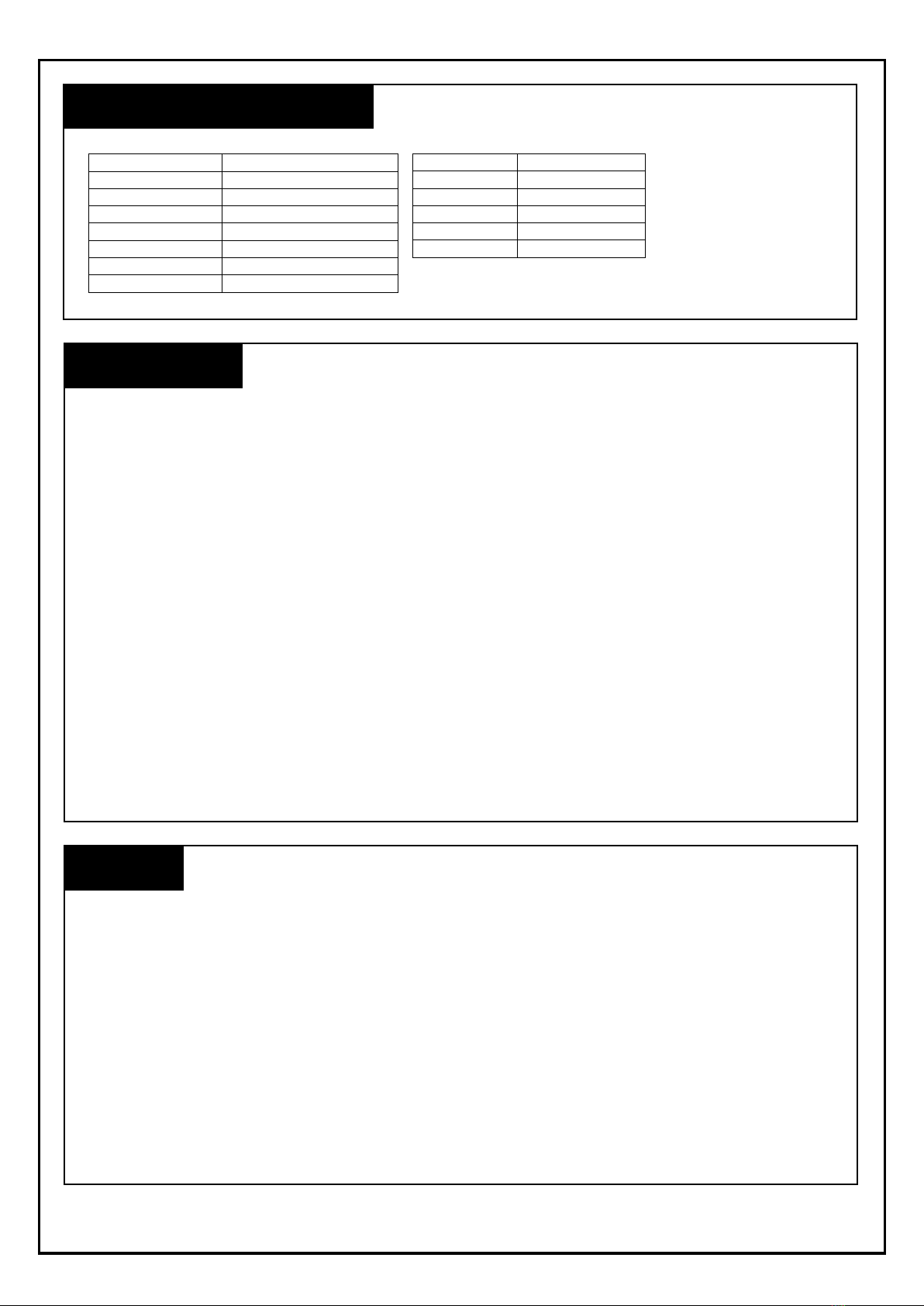
Model PH-0.8L-HL
Max Flow 270 lph
Max Head 6m
Tank Capacity 0.8 litres
Volts 240 V / 0.64 A
Hz 50 Hz
Discharge Size 3/8"
High-level Alarm Volt Free
INSTALLATION
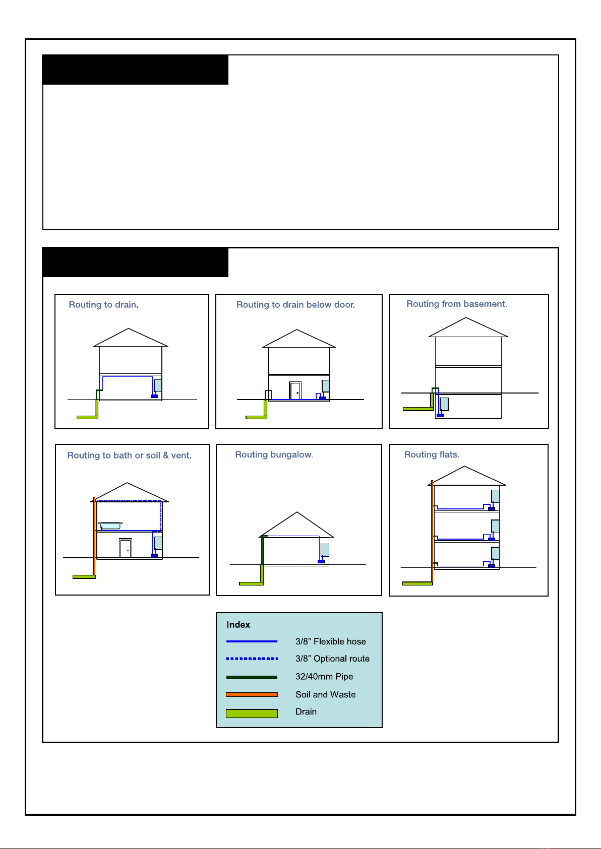
1. Your condensate pump is designed as an automatic condensate removal device for pumping away room
temperature condensate draining from condensing boilers. The pump is controlled by a float / switch
mechanism which turns the pump on to discharge the condensate when approximately 26mm of condensate
collects in a tank. The pump switches off automatically when the tank drains to approximately 13mm.
2. The condensate pump you have purchased is a high quality product that has been engineered to give
you a long and trouble-free service.
3. This pump is carefully packaged, inspected and tested to ensure safe operation and delivery. When you
receive the pump, examine it carefully to determine that there are no broken or damaged parts that may
have occurred during shipment. If damaged has occurred, please contact your supplier. They will assist
you in replacement or repair, if required.
4. Read instructions carefully before attempting to install, operate or service the pump. Know the pump
application, limitations and potential hazards. Protect yourself and others by observing all safety
information. Failure to comply with instructions could result in personal injury and/or property damage!
Retain instructions for fututre reference. Installation and connections are to be made by a qualified
person.
SAFETY
1. Do not use to pump flammable or explosive fluids such as petrol, fuel oil, kerosene, etc. Do not use in
explosive atmospheres. This pump should be used with liquids compatible with the pump component
materials.
2. Do not handle the pump with wet hands or when standing on a wet or damp surface, or in water. To reduce
the risk of electrical shock, be certain that the electrical supply is connected to a permanent EARTH.
3. For installations where property damage and/or personal injury might result from an inoperative or leaking
pump due to power cuts, discharge line blockage, or any other reason, a backup system and/or alarm
should be used.
4. Support the pump and piping when assembling and when installed. Failure to do so may cause piping to
break, pump to fail, motor bearing failures, etc
Height 122 mm
Inlet Height 45 mm
Length 220 mm
Width 134 mm
Cable Length 1.95 m
Hose 6m x 9.5mm (3/8")

PH-0.8L-HL Installation Instructions
2
INSTALLING THE PUMP
1. Carefully unpack the pump
2. Mounting the pump: The tank has two slots provided to mount the unit on a vertical surface such as an
adjacent wall. The slots are located on the ends of the tank. The pump must be level and the inlet must
be below the boiler condensate drain point.
3. The pump should not be installled in a manner that will subject it to splashing or spraying.
4. The following installation pipe routing options are available:
For further installation advice please call the technical support helpline on 0115 900 5858.
INSTALLING THE PUMP

PH-0-8L-HL Installation Instructions
3
ELECTRICAL CONNECTIONS
1. Shut off electrical power at fuse box before making any connections. All wiring must comply with
appropriate codes.
2. Connect the pump to voltage specified on label located on the pump:
Live - BROWN
Neutral - BLUE
Earth - YELLOW / GREEN
3. If seperate fused spur or plug is used, a 3.0 Amp fuse is recommended.
4. Connection of the high level safety switch / potential free contact should be made to either the boiler 240v
circuit or an audible alarm. The pump is fitted with a 240v micro switch, which will activate if the pump
starts to overfill in the event of outlet pipe blockage or pump failure. The following wiring diagrams show
how the switch can be connected into a boiler circuit or a separate audible alarm.
For further installation advice please call the technical support helpline on 0115 900 5858.
Boiler Connection
Audible Alarm Connection
N
L
E
Fused
Spur/Socket
L
N
E
NO
COM
NC
1
2
3
Boiler Condensate
Pump Connections
Permanent Live
N
EBoiler Connection
(If less than 3A)
BR
BL
G/Y
Bk Bk
BR
BL
G/Y
N
L
E
Boiler Fused
Spur
High level float
connection
L
N
L
L
N N
E
EE
NO NC COM
3
2
1
3
2
1
1
22
1
33
Condensate Pump Boiler Connector
Fused Spur/Socket
BR
BL
G/Y
Bk Bk
Junction
Box
Audible Alarm
Or Visual Alarm
L
N
L
N
E
E
NO NC COM
3
2
1

PH-0.8L-HL Installation Instructions
4
For further installation advice please call the technical support helpline on 0115 900 5858.
DRAIN CONNECTION
INLET CONDENSATE DRAIN CONNECTION
1. Position the pump beneath the boiler so that condensate flows into pump inlet freely (use either of the two
openings provided).
2. The inlet pipe should be positioned as close to the bottom of the tank as possible and the bottom cut at an
angle of greater than 30˚ to ensure the free flow of the condensate from the boiler.
OUTLET CONDENSATE CONNECTIONS
1. Connect the supplied 3/8” I.D tubing to the discharge adapter / non return valve. For best result, secure
tubing with clamps (not provided) but do not pinch, collapse or otherwise restrict the tubing. The non
return valve has a quick release mechanism with a 1/4 turn bayonet type fitting.
1/4 TURN NON RETURN VALVE
2. Tubing should rise vertically but not exceed the maximum shut off head (pumping height) of 5.6 metre
above the pump. Any horizontal runs should be taken into consideration when assessing the maximum
shut off. This shut off will be reduced if bends and horizontal runs are included in the outlet pipe work.
If in doubt please contact Pump House for advice.
3. At highest point angle tubing horizontally and create a downward slop to drainage point. Do not bend
sharply or twist the tubing in a way that might result in collapse or restriction of the tubing. Creating a
downward slope will allow condensate to drain by gravity and keep tubing empty.
4. If not possible to create a downward slope, try to create an inverted “U” trap directly above the pump at
the highest point.
COMMISSIONING & TESTING
1. Before commissioning, check for debris in the tank. Remove any material which might block the drain line
or drain into the pump tank.
2. Turn on power
3. Slowly fill the tank with clean water, as the float rises to the On Level position the motor should turn on.

PH-0.8L-HL Installation Instructions
5
For further installation advice please call the technical support helpline on 0115 900 5858.
COMMISSIONING & TESTING
4. Leave the clean water in the tank as this will effectively prime the pump ready for use and help to prevent
any flue products passing through the pump from the boiler condensate drain pipe.
This pump is designed for use with condensing boiler applications. Caution must be taken to ensure acidity
of condensate does not increase below the average pH of 3.0 (to prevent localised pocket of acid that acts
like a battery causing pitting) by routinely cleaning or flushing tank with fresh water.
MAINTENANCE & SERVICING
1. Before servicing the pump, disconnect the electric power at the fuse box for both the pump and the boiler
2. It is recommended that the pump be checked every six months for proper operation. Most important is to
check for debris blocking the pump discharge adapter/non return valave. Check for proper free movement
of pump float and switch and check for free, unrestricted movement of motor and fan.
3. Clean the holding tank and float with warm water and mild soap. Rinse completely when finished.
4. Check the inlet and outlet piping. Clean as necessary. Be sure there are no kinks in the outlet line that
would inhibit or restrict flow.
WARRANTY
This pump comes with a 1 year warranty. The warranty covers all parts with material or manufacturing faults.
The buyer’s only remedy is the replacement or repair of the defective parts. In no case can labour costs and
any consequential damage be cited as a basis for a complaint. Any returned units must be complete and
must be accompanied by a written list of the defects ascertained.
We are unable to accept any liability in case of nonconforming installation or noncompliance with the
specifications or maintenance recommendations.
CONFORMITY
All data contained in these specifications are solely intended to describe the product and do not constitute
warranted characteristics in the legal sense. Subject to technical change.
CE
Table of contents
Other Pump House Water Pump manuals