www.pumpsukltd.co.uk | info@pumpsukltd.co.uk
Units 3-4 Invicta Park, Sandpit Road, Dartford, Kent, DA1 5BU
The base frame must be earth bonded directly to the building earth system.
All wiring should be arranged such that it enters the control section through the appropriate cable glands.
Water supply and system connection
Connect the Autopress set ½”BSP ball valve (left side of cabinet) to a suitable water supply, incorporating an approved stop cock.
If the pressure available at the ball valve is below 0.3 bar, a low pressure orifice must be obtained and fitted.
Extend the 22mm plastic overflow pipe from the Autopress break tank to a position where an overflow will be noticed and rectified. Ensure the
warning pipe is able to handle the incoming water volume, if this is not the case then a reducing valve should be fitted to the incoming water
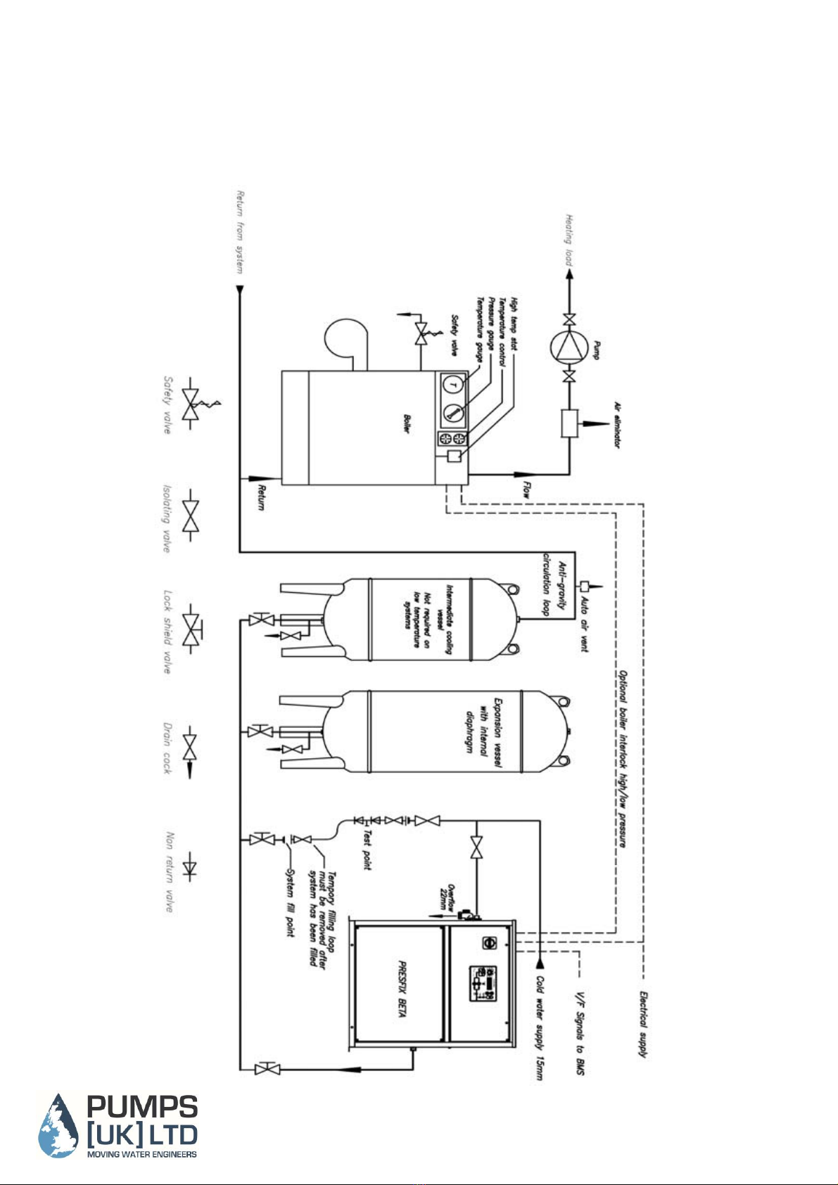
supply. Connect the pressurisation port ½” BSP (right hand side of cabinet) to the expansion vessel pipeline which in turn should be connected
to the suction side of the system circulating pump. Quick fill and isolating valves must also be fitted to this line (see connection sketch Fig 1)
The Break tank is constructed to have a weir slot as required by the water bylaws to prevent back flow contamination, if the inlet ball valve or NRV
suffered a catastrophic failure the overflow may not be able to keep up with the inflow in which case excess water will be ejected through the weir slot
and onto the plant room floor, if this is not acceptable then consideration should be given to fitting the pressurisation set onto a try with overflow to
drain
Commissioning
1. Fill the system with water via the quick fill filling loop to the system fill pressure, this filling loop must comply with local water authority bylaws
and contain double check valves. The filling loop must be completely removed after the system has been filled.
The pressurisation unit must never be used to fill the system.
The maximum running time for pumps fitted to this product must not exceed 4 hours in any 24 hour period.
It is essential that all air is allowed to escape freely via air vents and radiator vents etc. All air must be evacuated from the system for this
product to operate correctly.
2. Turn on the water supply feeding the product break tank. Water treatment crystals/chemicals must never be introduced to the system via the break
tank.
3. Check that pumps have been fully evacuated of all air by removing the bleed screw of each pump where fitted and allow water to escape
until no air is present. Replace bleed screws.
4. Before the unit is opened up to the main system pressure check the pre-charge in the internal vessel. The pre-charge should be set to
approximately 0.35bar below the system fill pressure. Charge as necessary with Nitrogen or dry air. Open system valve to Presfix Beta unit.
System set points
System set points are entered via the front panel interface.
To stop unauthorised adjustment of set points a lock switch is positioned on the back of the display PCB this will need to be switched to the
unlocked position to enable set points to be changed.
Switch the selector switch to the appropriate set point and the display will show the value of that particular set point, if the value is blinking on/off the
value is able to be modified, if the value is not blinking it means that the lock is active and the value will not be able to be changed.
To increase or decrease the value press the up/down buttons. The longer you press the button the quicker the change rate.
Once you have selected the correct value move the selector switch to next set point that you wish to change, the values in the previous set point
will be automatically saved.
Once you have entered data into all relevant set point parameters the selector switch should be set to the Auto position. If the data is to be locked
then switch the lock switch on the rear of display PCB to the locked position.
Set point description
Delay Start
This set point is adjustable between 0-10 seconds and is used to delay starting the pressurisation pump for the set period. This can be useful especially on
chilled water system where it can be very difficult to remove all air.
Low pressure set point
This set point is typically set approximately 0.4 bar below the fill point.
High pressure set point
This set point is typically set approximately 0.2 bar above the final working pressure.