INLET PRESSURE should fall within the specifications of the
pump.
• High RPM, high temperatures, low vapor pressures or high
viscosity may increase acceleration loss of liquids.
• Optimum pump performance is obtained with +20 PSI (1.4
BAR) inlet pressure. With adequate inlet plumbing, most
pumps will perform with flooded suction.
• After prolonged storage, pump should be purged of air to
facilitate priming. Disconnect the discharge port to allow
liquid to pass through pump and measure flow.
BYPASS TO INLET –care should be exercised when
deciding the method of bypass from control valves.
• It is recommended that the bypass be directed to a baffled
reservoir tank, with at least one baffle between the bypass
line and the inlet line to the pump.
• Although not recommended, bypass liquid may be returned
to the inlet line of the pump if the system is properly
designed to protect your pump.
• A low-pressure, flexible hose should be used from the
bypass connection to the inlet of the pump.
• Caution should be exercised to avoid under sizing the bypass
hose diameter and length.
• Check the pressure in the bypass line to avoid over-
pressurizing.
USING CHEMICALS
Chemicals can be mixed into the fluid and it is necessary to
understand whether these chemicals will damage the pump or
other system components. Another way to put chemicals into
the fluid is with a downstream injector.
An injector works as a result of the difference of pressure
between the inlet side of injector and discharge side. In most
cases, the pressure on the discharge side cannot exceed 1/2 of
the inlet pressure. For example, 1000 PSI into an injector
should allow up to 500-600 PSI spray pressure on discharge
side. There are dual-function nozzles that permit high
pressure, chemical free rinse and low pressure, chemical
spray. These are convenient for the operator and will not harm
a properly designed system.
The advantages of an injector are:
Fewer items touching chemical, the chemical injection rate can
be controlled, and applying chemical at lower pressure
increases chemical use efficiency.
HEATING FLUID
The pumps may sometimes be used with downstream heaters
and precautions need to be taken to protect the system and
persons from harm. Refer to the skilled staff at the equipment
manufacturer for guidance and proper system care. Please be
aware that heated water expands, and additional pressure
release safety devices may be required.
SYSTEM DESIGN
A pump is the heart of every system and proper selection is
critical to equipment function and durability. If a pumping set
with excess flow is chosen, then energy and fluid is wasted.
Equipment effectiveness can decrease if excess pressure
results, and so can pump life.
TYPICAL APPLICATIONS AND THEIR PERFORMANCE
CONSIDERATIONS
PEST SPRAYING
This application can have specific chemical usage requirements
and application pressure limits, so use the included
information as a guide only. Refer to label requirements for
each specific chemical.
LINE LOSS
When choosing a pump for spraying, pressure loss in the hose
must be considered. The pressure is greatest at pump and
decreases over the length of the hose. Typically, these systems
utilize very long hoses, 200-300 ft. is common, and requires a
certain minimum amount of performance to move the flow
through the lengths of hose. For example, a 3 GPM system will
require (lose) 50 PSI per 50 ft. of 3/8” ID hose. A pump with
only 60-70 PSI may not provide the desired performance at the
end of the hose. See reference charts to assist in system
design.
DO NOT return bypass fluids from regulating valve directly
back to inlet of pump. The returned fluid will contain large
amounts of air bubbles that will cause cavitation and damage
in the pump head. Also, the small amount of returned fluid can
heat up rapidly and lead to further cavitation and component
damage. It is recommended to route bypass back to inlet of
filter to allow air bubbles to dissolve and water to cool prior to
entering pump.
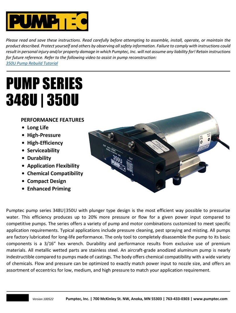
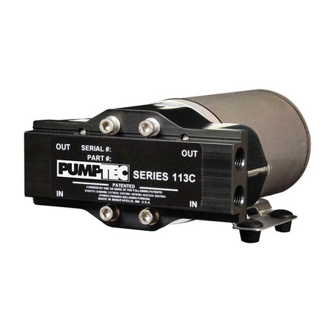
The pumps are shipped assembled to a custom-made motor
based upon your specifications. It is not necessary to order a
motor separately. Communicate your specification
requirements and the supplier will assist with pump options.
Please use the following charts as a guide to understand the
basic system requirements.
NOTE: Nozzle sizes in the performance chart are additive. For
example, 2 pieces of ’02 nozzle equals the performance of 1
piece of ’04.
Nozzles create restriction (pressure) in the system. If unsure of
the nozzle size needed for desired performance, refer to
Nozzle Performance Chart. If you are sure of your nozzle size,
but unsure of which pump set to choose, use the Nozzle
Performance Chart along with the Horsepower Chart to
determine your required pump specification. See next page.

