Pure line PL1616 User manual

Pure Flow Variable Speed Pump
Installation And User Guide
Model: PL1616
Important Safety Instructions. Read And Follow All Instructions.
Save Instructions.

READ AND FOLLOW ALL INSTRUCTIONS
ATTENTION INSTALLER: This manual contains essential information about the installation, operation,
and safe use of this pool pump. Please remember to furnish this manual and all other instructional
documents to the end user of this product.
Failure to read and follow instructions can result in serious injury.
To prevent potential injury to self or product and to avoid unnecessary service calls, please read the
manual carefully. Look for the following symbols and signal words and be alert to potential injury.
WARNING- This is a safety-alert symbol. Whenever you see this symbol in this manual or
on the pump itself, look for the following signal words to alert potential dangers.
DANGER- A licensed electrician MUST complete, in full, all electrical installation
CAUTION- This represents a potentially hazardous and dangerous situation. If not careful,
it may result in bodily or property damage.
IMPORTANT SAFETY INSTRUCTIONS
General Warnings
●Never open the inside of the drive motor enclosure.
●The pump is not submersible.
●Install this pump in a place with good drainage
●Before starting, all system valves must be in a position that allows water to return to the pool.
●Code requirements for the electrical connection differ from state to state. Install equipment
according to the National Electrical Code.
●Switch pump to OFF by disconnecting the main circuit to pump BEFORE servicing pump
WARNING- To reduce the risk of injuries, do not permit children to use this product unless
supervised.
WARNING- Risk of electrical Shock. Connect only to a circuit branch protected by
aground-fault circuit interrupter (GFCI). If you cannot verify if the circuit is protected by a GFCI, contact
a qualified technician. Pump must be permanently connected to a GFCI.

WARNING- This unit must only be connected to a supply circuit that is protected by a
ground-fault-circuit protection (GFCI). The GFCI should be provided by the installer and should be
tested on a routine basis. To test the GFCI, simply push the test button. The GFCI should interrupt
power. Push the reset button and the power should be restored. The GFCI is defective if it fails to
operate in this manner. If the GFCI interrupts the power to the pump without the test button being
pushed, this indicates a ground current is flowing and has the possibility of causing an electric shock.
Do not use the pump. Disconnect the pump and correct the issue with a qualified service technician
before using.
WARNING- To reduce the risk of electric shock, immediately replace damaged cords.
WARNING- This pump is only for use with permanently-installed pools and may be used
with hot tubs and spas, if so marked. Do NOT use with storable pools. A permanently-installed pool is
constructed in or on the ground or building, such that it is capable of being readily disassembled for
storage and reassembled to its original integrity.
WARNING- Hazardous Pressure- During startup, normal operation, and after pump shuts
off, the pool and spa water circulation system operates under hazardous pressure. Please stand clear
of the circulation system during pump start-up. Before servicing your pool equipment, make sure all
systems and pump controls are in the off position and the filter manual air relief valve is open. Also
make sure all system valves are set in a position that allows water to return to the pool. Do not change
the filter valve position while the system pump is running. All suction and discharge valves must be
open when starting the circulation system. Failure to follow safety and operational instructions could
result in damage, severe personal injury, or death.
WARNING- Separation Hazard- Please ensure the strainer cover is properly secured to
the pump housing. Do not operate pool and spa circulation systems if a system component is not
assembled properly, damaged, or missing. All suction and discharge valves must be open when starting
the circulation system. Failure to follow safety and operational instructions could result in damage,
severe personal injury, or death.
Pump Overview
This manual contains essential information about the installation, operation, and safe use of this pool
pump. Failure to install according to the defined instructions will void your warranty.

Pump Installation
Before servicing, all water circulation systems and pump controls must be in the off position, release all
the pressure from the system.
WARNING- This pump should be served and installed by licensed professionals.
WARNING- Keep pump away from children
General Features
●Variable speed pumps provide maximum energy savings
●Simple interface that is easy to operate and program
●Real-time clock with 24-hour memory
●Removable strainer basket with a built-in thermal overload protection
●Totally-enclosed fan cooled (TEFC) motor
Location
Place the pump as close to the pool as it allows and run suction lines as direct as possible to reduce
friction loss. All suction lines should have a continuous slope upward from the lowest point in line.
Joints must be tight (but not over-tightened). Suction line diameter must equal or be larger than the
discharge line diameter. The suggested installation of the pump is 12” above the pool water level. The
pump should not be installed more than 30” above the pool water level.
Though the pump is designed for outdoor use, we strongly advise you to protect the electrical
components from the weather. Select a well-drained area that does not flood. Do NOT install pump in
a damp or non-ventilated area. Pump motors require free circulation and air for cooling.
Pump Mounting
Install the pump on a firm, level base or pad to meet all local and national codes. Fasten pump to base
or pad with screws or bolts to reduce vibration and stress on the pope or hose joints. The base MUST
be solid, level, rigid, and vibration free.

Pump Plumbing
There are many different ways a pool pump can be plumbed due to space requirements, existing
plumbing, water features, etc... Due to these scenarios, we have listed some general best practices to
adhere to when plumbing a pool pump.
Pool Plumbing Best Practices
●It is best to use larger plumbing on the suction side of the pump, as this will allow the pump to prime
easier and put less stress on the pump resulting in longer pump life.
○ For example, use 2” plumbing on the suction side of the pump and then use a 2” x 1.5” reducer
bushing to reduce down to the 1.5” pump suction port. If you can only install larger plumbing on
the 12” of pipe going into the pump, then this is fine, as you will still see benefits.
●Use a minimum of 12” of straight pipe going into the suction port of the pump.
●Avoid the use of 90-degree elbows within 12” of the suction port or discharge port of the pump. The
fewer 90-degree elbows, the better.
●The use of two 45-degree fittings is better than one 90-degree elbow.
●If you are having problems with your pump keeping prime after the pump shuts off, then the use of a
check valve on the suction side of the pump will help with keeping the pump primed. Make sure the
check valve is not too close to the suction port of the pump. See check valve placement
recommendations listed below.
Check Valve Placement
1.5” Plumbing - Check valve not to be placed within 7.5” of pump suction port
2” Plumbing - Check valve not to be placed within 10” of pump suction port
2.5” Plumbing - Check valve not to be placed within 12.5” pump of suction port
Filter
Pump
Check Valve
3 Way Valve
12” straight pipe
Pump Discharge Port
Pump Suction Port
Ideal Installation
Filter
Check Valve Placement
• 1.5’’ plumbing, more than 7.5’’
from pump suction port
• 2’’ plumbing, more than 10’’
from pump suction port
• 2.5’’ plumbing, more than 12.5’’
from pump suction port
Suggested installation of pump is 12’’ above
water level.
The pump should not be installed more than
30’’ above water level.

Piping
1. Larger piping sizes improve pool plumbing.
2. Piping on the suction side of the pump should be the same or larger than the return port.
3. Plumbing on the suction side of the pump should be as short as possible.
4. For most installations, its is recommended you install a valve on both the pump suction and
return lines. This allows you to isolate the pump during routine maintenance. However, the valve,
elbow, or tee installed in the suction line should be no closer to the front of the pump than 5 times
the suction line diameter.
Example: A 2.5” pipe requires a 12.5” straight run in front of the suction inlet of the pump. This will help
the pump prime faster and last longer.
Note: Do NOT install 90-degree elbows directly into the pump inlet or outlet.
Fittings and Valves
1. Do not install 90-degree elbows directly into the pump outlet.
2. Flooded suction systems should have gate valves installed or suction and discharge pipes for
maintenance. However, the suction gate valve should be no closer than 5 times the suction pipe
diameter.
3. Use a check valve in the discharge line when using this pump for any application where there is
significant height to the plumbing after the pump.
4. Be sure to install check valves when plumbing in parallel with another pump. This helps prevent
reverse rotation of the impeller and motor.
Filter
Pump
3 Way Valve
90° on suction side of pump
Ideally no 90° within 12’’ of
pump suction port
90° 90°
Filter
Improper Installation
Pump Discharge Port
Pump Suction Port

Electrical Requirements
1. Install all equipment in accordance with the National Electrical Code and all applicable local
codes and ordinances.
2. A means for disconnection must be incorporated in the fixed wiring in accordance with the wiring
rules.
Voltage
The voltage at the motor must NOT be more than 10% above or below motor nameplate rated voltage
or the motor may overheat, causing the overload tripping.
Grounding and Bonding
Install, ground, bond, and wire motor in accordance with local or national electrical code. Make sure to
permanently ground the motor. Use green ground terminal provided under motor canopy or access
plate. Use the appropriate size and wire type required by code. Connect motor ground terminal to
electrical service ground.
Reference NEC codes for all wiring standards including, grounding, bonding, and general wiring
procedures.
Wiring
If the pump comes with a cord and plug, no wiring is needed. In some areas, power cords are
not provided to local electrical standards. Wire pump according to local electrician codes. Follow
the instructions below for wiring.
WARNING- All electrical wiring must be performed by a licensed electrician.
WARNING- All electrical wiring must conform to local codes and NEC regulations.
WARNING- Use copper conductors only.

Screw 1: Ground wire
Screws 2 & 3: Either of two live wires
Screws 4 & 5: Not used
CAUTION- NEVER run the pump dry. Running pump dry may damage seals, causing
leakage, flooding, and voids warranty. Fill strainer housing with water before starting the motor.
1. Remove the AC power connection terminal box cover. There are a total of 5 screws inside the
terminal box.
2. Ensure that the available electrical supply is suitable for the motor’s voltage, phase, cycle, and
that the wire size is adequate for the HP rating and distance from the power source.
3. The voltage from the power source must be within 90%-110% of the motor’s rated voltage.
Failure to keep within this range can result in overload tripping and reduced longevity.
4. Install, ground, bond, and wire the motor in accordance with local NEC requirements.
5. Ground the pump by connecting a grounding wire from the electrical service ground terminal to
the motor grounding screw.
6. Bond the motor to the pool structure. In short, this means creating an electrical connection
between the pump and swimming pool. This helps prevent potential hazards if you run into
electrical issues with the pump.
Start-Up and Operation
Prior to Start-Up
If it is necessary to perform a pressure test prior to initial use to ensure pump is functioning properly,
then the following criteria should be considered:
1. Hire a professional for the test.
2. Ensure all pump components are sealed properly to prevent leaks.
3. Remove any trapped air in the system by fully opening the filter air relief valve until a steady
stream of water is discharged.
4. Allow no more than 40 PSI at water temperature no higher than 100 F.
5. Do not run a pressure test for longer than 24 hours. Inspect all parts immediately to verify they
are intact and functioning properly.
6. Fill strainer housing with water to suction pipe level. Never operate the pump without water.
Wate acts as a coolant and lubricant for the mechanical shaft seal.
Do NOT add chemicals to the pool/spa system directly in front of pump suction. Adding undiluted
chemicals may damage pump and voids the warranty.

Priming Pump
All suction and discharge valves must be open as well as filter air relief valve when starting the circulat-
ing pump system. Failure to do so could result in severe personal injury.
Priming Pump Placed Below Water Level
● The pump will prime itself if it is placed lower than the water level.
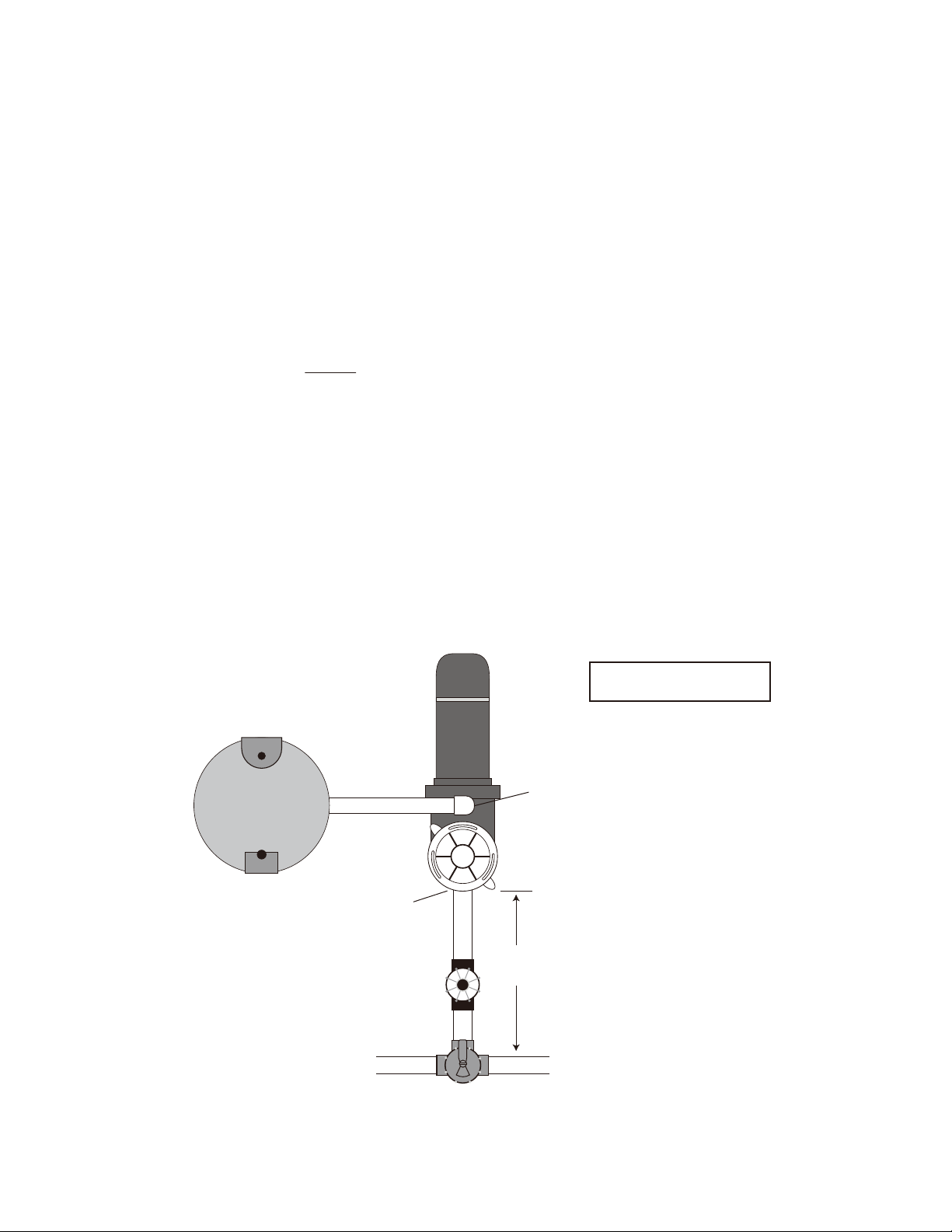
Priming Pump Placed Above Water Level - If water level is lower than the pump, then following
these instructions for priming. The suggested installation of the pump is 12” above the pool water
level. The pump should not be installed more than 30” above the pool water level.
● Turn Power off to pool pump
● Make sure pool water is halfway up pool skimmer face
● Open suction valves
● Open discharge valves
● Open filters air release valve
● Unscrew and remove pump lid
● Remove any debris from pump basket
● Clean pool filter if needed
● Clean pool skimmer basket if needed
● Fill pump strainer basket with water from garden hose
● Clean and lubricate strainer cover O-ring each time it is removed. Inspect O-ring and place it
back on the strainer cover.
● Turn the strainer cover clockwise to tighten. NOTE: Tighten the strainer cover by hand only.
NO wrenches.
● Turn on the power to the pump and wait for the pump to prime. This may take up to five (5)
minutes. Priming time depends on the vertical length of the suction lift and the horizontal length
of the suction pipe. If the pump does not prime within five minutes, stop the motor and
determine the cause. Be sure all suction and discharge valves are open when the pump is
running.
● Once the water starts coming out of the pool filter air release close pool filter air release
Helpful Videos for Pool Pump Priming
● Video on How to Prime a Pool Pump -
https://www.inyopools.com/HowToPage/how_to_prime_ a_pool_pump.aspx
● Video on How to Determine Why a Pool Pump Won't Prime -
https://www.inyopools.com/HowToPage/how_to_determine_why_a_pool_pump_won_t_prime.aspx
● Video on How to Identify and Correct Air Leaks -
https://www.inyopools.com/HowToPage/how_to_identify_and_correct_air_leaks.aspx
● Video on How to Correct Swimming Pool Plumbing Issues -
https://www.inyopools.com/blog/how-to-fix-priming-problems-in-your-pool-plumbing/
ATTENTION- Before removing strainer cover:
ATTENTION- Wait five seconds before re-starting the pump. Failure to do so may cause
reverse rotation of the motor and seriously damage the pump.
1. STOP PUMP before proceeding.
2. CLOSE VALVES in suction and outlet pipes
3. RELEASE ALL PRESSURE from pump and piping system using filter manual air relief valve.

WARNING- Allowing the pump to freeze will void your warranty
Using The Control Panel
WARNING- Only use propylene glycol as antifreeze in your pool/spa. Propylene glycol is
nontoxic and will not damage plastic system components. Other antifreeze combinations may damage
plastic components in the system. Drain all water from the pump and piping whenever you are expecting
freezing temperatures or when storing the pump for a long period of time.
Keep motor dry and covered during storage. To avoid condensation/corrosion issues, do NOT cover or
wrap the pump with plastic film or bags.
1. Drain water level below all inlets to the pool.
2. Remove drain plus from bottom of strainer body and remove the strainer cover from the housing.
3. Disconnect pump from mounting pad, wiring system (AFTER power has been turned OFF), and
piping systems.
4. Once the water is removed from the pump, re-install the strainer cover and drain plugs. Store
pump in a dry area.
1 2 3
Auto
start
Quick
Clean
Set
Time
Start
Stop Mode
on
warn
Anti
Inv
Enter
+
-
Running
Current Time
Current Speed
Current Watt in Manual Mode
Current Mode
1
Running/Stop
Start/End Time in Schedule Mode
S05:00--->E08:00
Schedule Cycle2
12:15
1200 RPM
Quick
Set
Alarm
2
5
4
3
6
7
8
Maintenance
● Clean strainer basket regularly. Do NOT strike the basket to clean. Inspect strainer cover gasket
regularly and replace as necessary.
● Pumps have self-lubricating motor bearings and shaft seals. No lubrication is necessary.
● Keep the motor clean. Ensure air vents are free from obstruction to avoid damage. Do NOT use
water to hose off the motor.
● Occasionally, shaft seals must be replaced. Replace with a genuine seal assembly kit.
Storage and Winterization
Do not purge the system with compressed air. Doing this can cause inside components to explode,
causing injury or death. Only use a low pressure (below 5 PSI), high volume blower when air purging
the pump.

Controls and LEDs
1. 1 Button/LED: When in Manual Mode, button 1 means manual speed 1. When in Schedule
Mode, this button means cycle 1. The LED lights ON means the pump is running at Speed 1 in
Manual Mode or running at cycle 1 in Schedule Mode.
2. 2 Button/LED: When in Manual Mode, button 2 means manual speed 2. When in Schedule
Mode, this button means cycle 2. The LED lights ON means the pump is running at Speed 2 in
Manual Mode or running at cycle 2 in Schedule Mode.
3. 3 Button/ LED: When in Manual Mode, button 3 means manual speed 3. When in Schedule
Mode, this button means cycle 3. The LED lights on means the pump is running at Speed 3 in
Manual Mode or running at cycle 3 in Schedule Mode.
4. Auto Start: If LED is ON, the pump will start running automatically when power is given. LED
OFF means disable.
5.Anti-Button: Antifreeze function ON/OFF.
6. Quick Set: Set up for current mode.
7. Inv: Shows basic parameters
8.Enter: Save the current value and come into the next set up item in quick edit mode.
9. Arrows +/- Buttons: Left arrow moves cursor left one digit. Right arrow moves the cursor right
one digit. ‘+’ increases a digit. ‘-’ decreases a digit.
10. Quick Clean: Runs pump at a certain speed for a certain duration of time. The speed and
duration can be preset by pressing the “Quick Set” button when in quick clean mode.
11. Set Time: Sets local time for pump
12. Start Stop: Starts or stops the pump. The LED will turn off once speed reduces to 0.
13. Mode: Switches among Manual Mode, Schedule Mode, and external control, if you have one.
14. LEDs: ON: Indicates the power is on.
Warning: LED is on if a warning condition is present.
1 2 3
Auto
start
Quick
Clean
Set
Time
Start
Stop Mode
on
warn
Anti
Inv
Enter
+
-
Running
Manual Speed 1
12:15
0750 RPM
0028 WATT
Quick
Set
Alarm
9
12
10
11
14
13

Alarm: LED is on if an alarm condition occurs.
Operating The Pump
This section details how to operate the pump using the control panel buttons.
Starting The Pump
1. Make sure the pump's power is ON and the green ON power LED is illuminated.
2. Press the “Start Stop” button to start the pump.
Stopping The Pump
1. Press the “Start Stop” button to stop the pump.
Running The Pump At Preset Speeds
The pump is programmed with 3 default speeds: 750, 2500, and 3450 RPMs. Each preset speed is
assigned a speed button (1,2,3). Follow the instructions to run the pump at each preset speed.
1. Make sure the pump is in manual mode by pressing the “Mode” button.
2. Press the speed button (1, 2, or 3) corresponding to the desired preset speed. The LED light
above the button will illuminate.
3. Press the “Start Stop” button and the pump will ramp to the selected preset speed.
Adjusting The Pump Speed
1. Press the “+” or “-” button to increase or decrease the speed levels. New values will be
automatically saved.
Running The Pump In Schedule Mode
1. Make sure the pump is in Schedule Mode by pressing the “Mode” button.
2. The LED light above the Cycle button will turn on, indicating the current cycle. The pump will
come into the proper cycle according to the current time.
3. Pressing the “Start Stop” button quickly ramps the pump to the preset speed of the current cycle.
Setting Schedule Cycles 1-3 (Factory Settings)
Cycle # Start Time (24 hours) Stop Time (24 hours) Speed (RPMs)
1 06:00 09:59 1700
2 10:00 15:59 3000
3 16:00 05:59 1200
1 2 3
Auto
start
LED lit

Programming Each Cycle
1. Go to Schedule Mode by pressing the “Mode” button until it reads “Schedule Cycle.”
2. Press the “Quick Set” button to go into the speed setting page of cycle 1.
3. Change the speed by pressing the arrow and “+ / -” button.
4. Press “Enter” to save and to go into the start time setting page for cycle 1.
5. Change the start time by pressing the arrow and “+ / -” button.
6. Press “Enter” to save and to go into the stop time setting page for cycle 1.
7. Change the stop time by pressing the arrow and “+ / -” button
8. Press “Enter” to go into the next speed setting page. Repeat steps 1-7 for cycles 2 and 3.
Setting The Time
1. First, make sure the screen is on the home page.
2. Press the “Set Time” button.
3. Change the time by pressing the arrow and “+ / -” button.
4. Press “Enter” to save and to go back to the home page.
Setting Quick Clean
The factory-set quick clean speed is at 3450 RPMs with a duration of 5hours.
1. First, make sure the screen is on the home page.
2. Press the “Quick Clean” button to go into the quick clean mode.
3. Press the “Quick Set” button to go into the clean speed setting page.
4. Change the speed by pressing the arrow and “+ /-” button.
5. Press “Enter” to save and to go into clean time duration setting page.
6. Change the clean time by pressing the arrow button and “+ /-” button.
7. Press “Enter” to save and go back to the home page.
Setting The Ant-freeze
The factory-set antifreeze function is set to 750 RPMs when the temperature is below 4 degrees Celsius.
1. Make sure the screen is on the home page.
2. Press the “Anti” button to go into the antifreeze page.
3. Press the “Quick Set” button to go into enable/disable setting.
4. Change setting to “OFF” to make it inactive. Keep it “ON” to make it active.
5. Press “Enter” to save and to go into antifreeze speed setting page.
6. Change the antifreeze speed by pressing the arrow button and “+/ -” button.
7. Press “Enter” to save and to go into the temperature setting page.
8. Change the temperature by pressing the arrow button and the “+/ -” button.
9. Press “Enter” to save and go back to the home page.
Basic Parameters
Noise: The noise for the pump is adjustable. The larger the noise value is, the more electric protection
pump will have. The factory-set noise level is 10. This meets the electrical leakage standard for most
areas. Please DO NOT change if unnecessary.
Pump Address: This is available only in pumps with the RS485modbus connector.
Minimum Speed: You can run the pump at minimum speed. The factory-set minimum speed is 450
RPMs.
1. Make sure the screen is on the home page.
2. Press the “INV” button to show the pump’s performance data.
3. Press the “Quick Set” button for the settings page.
4. Press “Enter” several times until “Min-Speed” is on the screen.
5. Change the minimum speed by pressing the arrow and “+/ -” buttons.
6. Press “Enter” to save.
7. If no other changes are needed, press the “Quick Set” button and go back to the home page.

Maximum Speed: You can run the pump at maximum speed. The factory-set minimum speed is 3450
RPMs.
8. Make sure the screen is on the home page.
9. Press the “INV” button to show the pump’s performance data.
10. Press the “Quick Set” button for the settings page.
11. Press “Enter” several times until “Max-Speed” is on the screen.
12. Change the maximum speed by pressing the arrow and “+/ -” buttons.
13. Press “Enter” to save.
14. If no other changes are needed, press the “Quick Set” button and go back to the home page.
External Speed, Baud Rate, Wait Time, Accelerate and Decelerate Time: This is available only in
pumps with the RS485 modbus connector.
Electric Consumption: This is the accumulated energy consumption of the pump from the last restore of
factory settings to the current moment. It is normal if the reading is not 0 before running the pump, as
pumps are tested before leaving the factory.
Restore Factory Settings: This allows you to delete all of the settings of the pump and all data will be
restored to factory settings.
Maintenance
This section covers how to service and maintain the pump.
The Strainer Basket
The strainer basket is located in the pump strainer and is visible when looking down into the pump lid. We
recommend inspecting and cleaning the basket at least once a week to keep the pump efficiently working.
1. Stop the pump and turn power OFF.
2. Relieve the pressure in the system.
3. Remove the pump lid
4. Take the strainer out and remove any debris from the basket. If the basket is damaged or
cracked, replace it.
5. Rinse out the basket.
6. Return basket to pump strainer.
7. Fill the pump strainer housing with water until the inlet port.
8. Re-install pump lid.
WARNING-Do not service the pump when it is plugged in. Failure to do so may cause injury.
Pump Motor
Although the pump is designed for outdoor use, it is highly recommended it be placed in a ventilated show
and avoiding direct sunlight and rain. Keep it away from any foreign matter, dirt, or moisture. If the motor
is wet, dry it before running.
Storage
1. Dry the pump before storing it.
2. Do not wrap motor and controller with plastic or other air-tight materials

Troubleshooting Your Pump
Issue Solutions
The motor will not start 1. Check for Incorrect wiring and loose electrical
connections.
2. Check switches, relays fuses, circuit breakers, and
GFCI’s. Replace if necessary.
3. Manually rotate the shaft from the back of the motor to
make sure it isn’t stuck.
4. If you have a timer, make sure it is working.
The motor shuts OFF 1. Check for Incorrect wiring and loose electrical
connections.
2. Low voltage or electrical overload
3. Motor damaged in transit
The motor hums but does not start 1. The centrifugal switch is stuck in the open position.
2. The impeller or motor shaft is stuck.
The pump wont prime 1. Make sure the strainer cover is sealed and the strainer is
filled with water.
2. Check the valves to ensure they are open and water can
freely circulate.
3.
4.
Check pump for air leaks in the plumbing. Check the
piping, joints, and connections.
Low flow 1. Blocked or restricted filter screen or suction pipe.
2. Pipe size too small.
3. Pressure is too high. Follow filter manual instructions to
replace/clean your media whether sand, cartridge, or
DE.
4. Leak in the pump
5. Restricted or undersized suction or discharged lines
Noisy Pump 1. Vibrations from pump base.
2. Check impeller for foreign objects
3. Used bearings from the motor, typically caused by water
or chemical damage. Replace bearings and all pump
seals.
If you have trouble priming your pump then many times,
this can be solved by reducing your total dynamic head
(TDH) within your plumbing system. The following items
can help reduce TDH and help with priming.
Make sure to have at least a 12" run of straight pipe
going into the suction outlet of the pump.
Remove as many 90-degree plumbing fittings as
possible from your plumbing, especially before the
suction port of the pump. Two 45's are better than one
90-degree fitting when it comes to TDH.
Use larger 2" pipe on the suction side of the pump.
Check out our guide on fixing priming problems with
your pool pump https://www.inyopools.com /blog/how-
to-fix-priming-problems-in-your-pool-plumbing/
●
●
●
●

Key Description Part Number
1 Pump Cover PL1585
2 Cover O-ring PL1586
3 Pump Basket PL1636
4 Pump Housing PL1632
5Diffuser O-ring PL1628
6 Diffuser PL1627
7Impeller 1.5HP PL1637
8Pump Housing O-ring PL1625
9 Seal Plate PL1631
11 Housing Bolts PL1623
12 Shaft Seal Assembly PL1592
15Drain Plug Assembly PL1629
16 Base Bracket PL1620
17 Base Bracket PL1621
Table of contents
Other Pure line Water Pump manuals
Popular Water Pump manuals by other brands

Xylem
Xylem FLYGT Compit 901 Series Installation, operation and maintenance manual

Munsch
Munsch NPC Series operating manual

Wilo
Wilo Wilo-IPH-O Installation and maintenance instructions

Sanwa Hydrotech
Sanwa Hydrotech META MTFO instruction manual

Flotec
Flotec BIOX Series Use and maintenance manual

Titan
Titan TTB583PMP instruction manual

Flotec
Flotec FPCI3350 owner's manual

Coleman
Coleman 90473E owner's manual

Grundfos
Grundfos AP40 Safety instructions and other important information

Gude
Gude GFP 5200 Translation of the original instructions

MagnaTex
MagnaTex MPL Series Operation and maintenance manual

Goulds Pumps
Goulds Pumps VIC Installation, operation and maintenance instructions