Pure Water Whisper 60 User manual

Whisper 60 modular
12/24 Volt DC 230VAC
User Guide and Installation handbook
PureWater –H. Fehlemann
Entsalzungsanlagen
Bodelschwinghstrasse 37
33142 Büren
Germany www.watermaker.de purewater@watermaker.de
Whisper 60 modular

Index
1.0 General Theory of Operation………………………………………………………... 2+3
2.0 Whisper 60 modular……………………………………………………………… 3
2.1 The general scope of application…………………………………………… 3
2.3 Explanation………………………........................................................................... 4
2.3.1 ETD Connections………………………………………………………………………. 4
2.4 Quality Monitor……………………………………………………………………….. 5
3.0 Performace……………........................................................................................... 6
4.0 Installation……………………………………………………………………………… 6
4.2 Preparation for Installation ………………………………………………………… 7
4.3.1 Feed Pump, Pre-Filter and Hose connections…… ……………………………..... 8
4.3.2 Product Water connection…………………………………………………………… 9
4.4 Hose connections to PH Stabilizer (Only COMPACT Models)…………. 9
4.4.01 Controls at the front Panel…………………………………………………… 9
4.4.1 Electric Control Box (Option)………………………………………………… 10
5.0 How to use the System………………………………………………………………... 11
Preservation Configuration Flow Diagram………………………………………… 12
6.0 Maintenance……………………………………………………………………………... 13
6.2 Short Term Storage/Fresh Water Flush…………………………………………… 13
6.3 LONG TERM STORAGE / PRESERVATION PROCEDURE……………….. 14
6.4 Re- Enter Service after Long Term Storage………………………………………… 14
6.5 Membrane Replacement……………………………………………………………….15
7.0 Flow Diagram with Air/Oil Separator………………………………………………… 16
Flow Diagram Standard Configuration……………………………………………… 17
8.0 Wiring……………………………………………………………………………………… 18
8.1.2 12/24 V DC Motor………………………………………………………………………… 18
9.2 The John Guest System……………………………………………………… 19
ii

Whisper 60 modular Guide
The Whisper 60 modular, individual parts:
Basic Unit Filtersystem Whisper
Feed Pump
Vane Pump 230V
Main Panel Pressure Vessel ETD
The dimensions of Motor and pump are subject to change, because different motors are used.
i

Whisper 60 modular Guide
Vorsichtsmaßnahmen Precautionary
Bitte beachten Sie folgende Punkte bevor Sie Ihre Whisper Anlage einbauen und in Betrieb nehmen!
Please pay attention to the following point’s bevor you install the system.
1. Die Anlage sollte innerhalb von 12 Monaten nach Auslieferung in Betrieb genommen werden.
You should take the unit into service within 12 month.
2. Die Anlage sollte ca. alle 7 Tage, oder in sehr heißen Gebieten alle 3 Tage mit Seewasser betrieben oder mit
Frischwasser gespült werden. You should flush the unit every 14 days, or in hot climate every 7 days.
3. Wenn die Anlage für eine lange Zeit außer Betrieb ist, sollte sie spätestens nach 12 Monaten
gespült und neu konserviert werden. If you have the unit not in use for a very long period, you should flush and
preserve the unit every 12 month.
4. Betreiben Sie die Anlage nie in Häfen oder in Gebieten wo Kraftstoff und Öl im Seewasser ist.
Don’t use the unit in ports and areas where the seawater is contaminated with fuel and oil.
5. Wenn Sie die Anlage in Frisch- oder Brackwasser betreiben sind keine weiteren Maßnahmen zu ergreifen.
No action has to be taken if you use the system in fresh or brackish water.
6. Schützen Sie die Anlage vor Frost. Prevent the unit from freezing
7. Lassen Sie die Membran nicht austrocknen. Wenn Sie die Membran aus irgendeinem Grund
ausbauen, ist es wichtig, dass sie sofort versiegelt wird. Don’t let the membrane dry out.
8. The Sea Water inlet should be a type which presses the water in during cruise.
9. Check the pre-filter condition regularly, when in use, an interval of every two weeks is recommended.
10.We recommend flushing the system after every use.
Caution!!!
The amount of produced fresh water is depending on Sea Water temperature and salinity.
For temperatures below 25°C you lose per 1°C –3% of rated fresh water output performance.
If the salinity is higher than 35000 PPM you could also lose output performance.
1

Whisper 60 modular Guide
1.0 GENERAL THEORY OF OPERATION
1.1 REVERSE OSMOSIS THEORY
Reverse osmosis, like many other practical scientific methods, developed from processes first
observed in nature. Osmosis is a naturally occurring phenomenon in which a semi-permeable
membrane separates a pure and a concentrated solution (a semi-permeable membrane is defined as
one that preferentially passes a particular substance). Every fluid has an inherent potential that is
directly related to the type and amount of solids in solution. This potential, referred to as osmotic
pressure, increases in proportion to relative concentration of a solution. A concentrated solution,
therefore, has an osmotic pressure that is higher than that of a pure solution. In an osmotic system,
the less concentrated solution will attempt to equalize the concentrations of both solutions by
migrating across the semi-permeable membrane. When enough pure solution migrates across the
membrane such that the inherent potential difference between the solutions in no longer higher than
the osmotic pressure of the membrane, the purer solution will stop flowing. If the pressure on the
concentrated solution is increased to above the osmotic pressure, fluid flow will be reversed. This
condition, called Reverse Osmosis, can be established by artificially pressurizing the more
concentrated solution using a high pressure pump. In this type of system, the concentrated solution
(normally referred to as feed-water) will become more concentrated as pure water flows out of solution
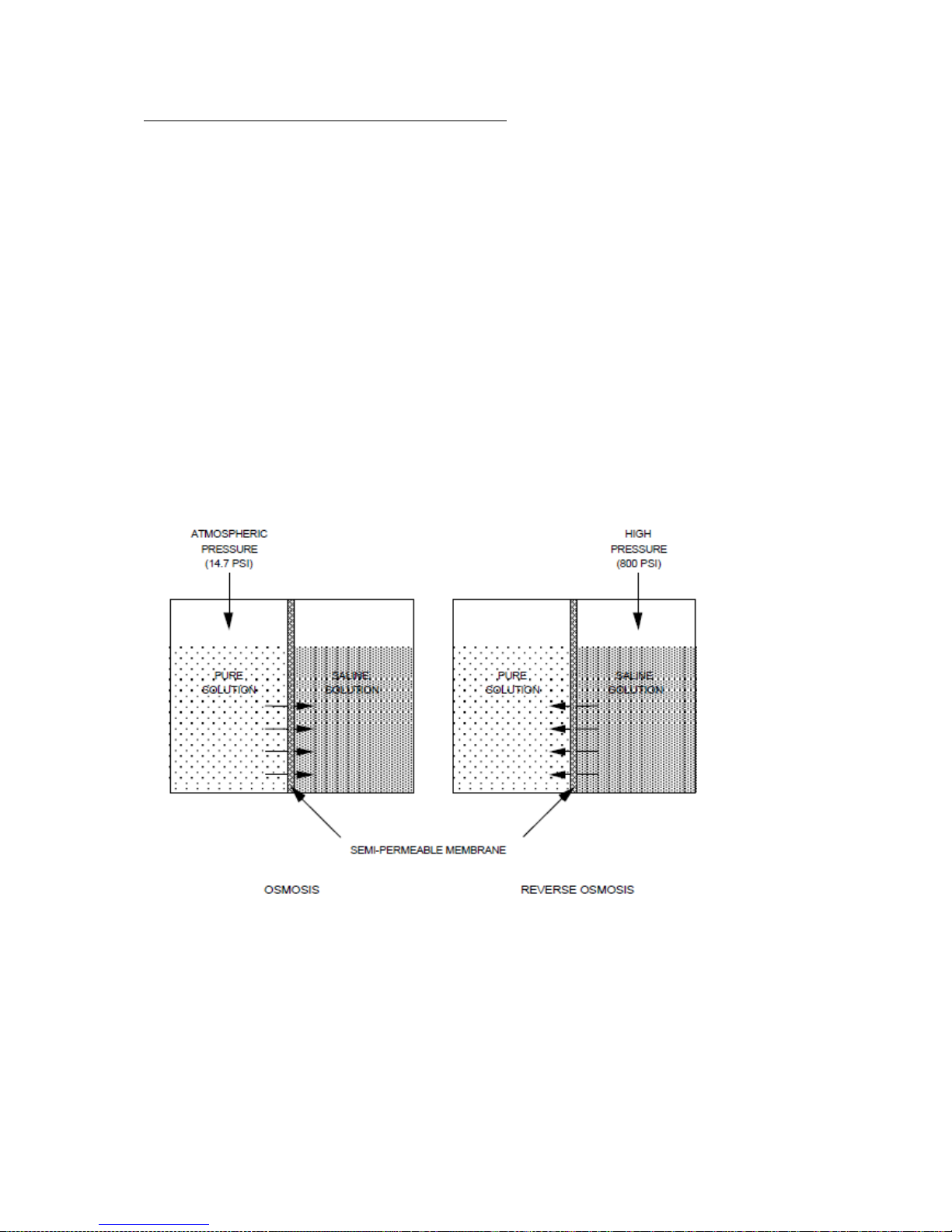
and across the membrane to the permeate side. Discounting the effects of feed-water temperature
and salinity, the operating pressure normally required to produce significant amounts of pure water is
at least twice the osmotic pressure of the membrane being used. Fig. 1.1
Figure 3.0 - Simple (Reverse) Osmosis Process
1.2 APPLICATION OF REVERSE OSMOSIS
Seawater contains many kinds of solids dissolved in solution. The most prevalent is common table salt
(Sodium- Chloride). Other minerals that may be present in solution are substances that usually contain
Various Compounds of Calcium and Sulfate. The sum of all of the solids dissolved in a particular
sample of water is referred to as Total Dissolved Solids or TDS. Seawater normally averages 32,000
ppm (parts per million) TDS although variations of 5000 ppm are common in various parts of the
world. The fundamental goal any desalination process is a significant reduction in the amount of
dissolved solids in water.
2

Whisper 60 modular Guide
In a Reverse Osmosis desalination system, most of the dissolved solids do not pass through the
Membrane but are instead carried along the membrane surface. This rejected water, referred to as
Brine, becomes increasingly more concentrated as it flows across the surface of the membranes and
is eventually piped to drain. The product water that flows through the membrane is referred to as
Permeate. The percentage of feed-water that enters the unit converted to permeate is called the
Recovery rate. On the Whisper systems the recovery rate is fixed at about 10%.
It should be noted that no system is capable of removing all 100% of the dissolved solids from
Seawater. Designed to reject approximately 99% of the TDS, the system allows 1% of the 35,000 ppm
TDS in the seawater to pass into the product water. This yields product water of less than 500 ppm,
the recommended TDS for drinking water. A system such as this is said to have a salt passage of 1%.
2.0 Whisper 60 System
2.1 The general scope of application for the WHISPER systems
You can use the WHISPER systems without restriction in all oceans around the world and in brackish
water areas. Take care in areas where sea water is contaminated with plankton. You must than check
the strainer more often. Clogging of the strainer could cause the vane pump run dry and fail.
The advantages of the WHISPER systems are:
No pressure regulation, the system regulates the pressure by itself.
A whisper quiet system.
Because of the energy recovery a good balance of power consumption.
Function
The heart of the system is the ETD (Energy Transfer Device)
The ETD produces out of a large volume of water with low pressure, high pressure, with a low volume of
water. The built in Energy recovery circuit pushes the ETD and saves energy by using the concentrate
back flow.
The advantage of this system is:
The system produces almost no noise.
No high pressure regulation is needed, the system regulates by itself.
It is a switch On/Off system.
New ceramic parts extend the time between overhaul.
More Water is pumped through the membrane which extends membrane life and increases water
quality.
.
3

Whisper 60 modular Guide
2.3 Explanation
High Pressure Gauge (at the ETD)
The High pressure Gauge shows the operating pressure. The range is between 35 and 55 Bar. That
depends of the type of Membrane installed. Generally we are using low energy membranes, so the
pressure is about 35-45 Bar.
Low pressure Gauge (at the panel)
The LP Gauge shows the pressure of the Vane Pump. The working pressure is 7-12 Bar.
Feed Pump (Vane Pump)
The feed pump pumps the water to the ETD
Flowmeter
The Flow Meter shows the amount of produced water in L/h
Sea Water Filter (Strainer)
The Strainer is a 60µ washable filter and reduces the particles to protect the vane pump.
Pre- Filter
The Pre-Filter is a 5µ changeable filter cartridge and protects the Membrane from fine particles.
Sample Valve (at the panel) not used on COMPACT Systems
With the Sample Valve you are able to take a water sample of your product water..
Fresh Water Flush System (FWF System)
The Fresh Water Flush System is a Carbon Filter activated with the valve at the Strainer.
The Carbon Filter reduces the possible chloride in the ships water system.
Clean/Rinse Kit Part Nr. 940
The Clean-Rinse Kit contains of a Three- way Cleaning Valve and a three Way selector Valve 1.
If you order the Kit with the unit the valves are already mounted. In COMPACT systems already
installed.
2.3.1 Connections to the ETD
4
Low Pressure Sensor High pressure Indicator HP hose Pressure (IN) HP Hose Membrane (OUT)
Hose Connections are on the back side. “ E “ is IN from the pre-filter “ S “ is OUT over board

Whisper 60 modular Guide
2.4 Quality Monitor (COMPACT Versions)
The Quality Monitor shows the quality of the product water in PPM TDS (Part per Million Total dissolved
Solids)
When starting the system the quality is always for a short period ( 30-45sec) high salinity. Shortly the
monitor starts to count down. As soon as the quality reaches the pre-set value (factory set point is
600PPM) the water is produced into the tank.
The controller is activating a diversion valve to control the destination of the product water.
The diversion Valve is located at the right side of the Main control panel. There is an emergency gray
button, to override the valve. Only to be used, when the controller is not working. Push and turn to the
right to lock.
5
Digital Display ppm
Switch OFF- AUTO- ON
Normal position is AUTO.
OFF= Controller is OFF
AUTO= Controller is in the AUTO
position. Automatic product water
transfer to tank.
ON= Product water is always
produced into tank.
LED display: RED Controller is OFF
Amber= Water is produced into tank.
Green= Water is going over board
Calibrating screw
Set Point for adjusting product water
set value. To readjust, push the
yellow set button and turn with a tiny
screwdriver the desired set point.
Return- push MEAS

Whisper 60 modular Guide
3.0 Performance
Sea Star Whisper 60 modular
Weight: 55 Kg
Power consumption:
Whisper 90 12V –21-24A 24V- 11-12A 230V 3,5A
Product Flow: 60 L/h +/- 10%
Operational Parameter:
Pressure: High Pressure: 500-950psi 35-55 Bar
Low Pressure: 7-12 Bar
Maximum Salinity: 46000 ppm (ppm= Parts per million)
Temperature Range: 1° C to 45° C
PH –Range: 2 - 11
The produced fresh water is better than WHO requirement.
4.0 Installation
4.1 Required Material
¼“ PVC Hose ( for the product water line )
½“ PVC Hose ( for the overboard Line )
½” PVC Hose ( for the Sea Water Line )
ca. 10 hose Cleats (1/2” SS )
Tie-Raps
15-25 mm² Cable (Option) depends on the length
Breaker 35 A (Option) Relay (Option)
6

Whisper 60 modular Guide
4.2 Preparations for Installation
For installation pay attention to the Flow Diagram on Page 16 and 17
Sea Water Filter (Strainer)
Place the Strainer direct after the Sea Cock. The Strainer has a 60µ washable Filter inside.
At the Strainer is the Selector Valve mounted. Here you can select either Sea Water operation or Fresh Water
Operation. The lower connection is for Sea Water, the upper connection is for the line from the Carbon Filter
(FWF System) or, if installed from the Selector Valve 1 if a Clean/Rinse Kit is installed.
Vane Pump. (Feed Pump)
The outlet of the Strainer has to be connected to the inlet of the vane pump.
Install the Vane Pump at or better below the waterline.
For the first use, fill the Vane pump with water.
Pre-Filter
The Pre-Filter can be installed above the waterline.
7

Whisper 60 modular Guide
4.3.1 Feed Pump, Pre- Filter and Hose connections
The Sea Water feed should be a marine grade Sea Cock, that you can close the Sea Cock individually.
The sea water inlet should be a scoop type, that the water is pressed in during cruise.
Step 1 Connect the Sea Water intake with a re- enforced ¾” hose to the lower hose barb at the valve at the
Strainer. Connect the outlet of the Strainer with the intake of the feed pump, or, if an Air separator is
used, to the inlet of the Air Separator, which is on 12/24V Systems the inlet of the attached Boost pump.
The outlet of the Air Separator is at the bottom of the housing. The left 8mm Line is to drain over board.
The upper connection of the Valve at the Strainer has to be connected with the outlet of the Carbon
Filter. (FWF System) The inlet of the Carbon Filter must be connected with your boats pressure water.
.
Step 2 Connect the outlet of the Feed Pump with the inlet of the red Pre-Filter. The outlet of the red Filter has to
be connected with the Sea Water inlet at the ETD, marked with E. The outlet, marked with S is the drain
over board.
Step 3 From the ETD Low Pressure outlet draw the supplied 10mm John Guest pipe to the Main Panels LP
Monitor.
Note!!
All connections past the Feed Pump have to be checked carefully, because there is already a
pressure of 7-10 Bar. Tighten the hose cleats carefully and check for leaks by the first use.
Use only hoses capable for 10 Bar pressure
--------- Pre –Filter installation completed ---------
8

Whisper 60 modular Guide
4.4 Hose Connections to PH Stabilizer (Only COMPACT Models, or Option)
Step 1 The Pre –Filter installation is completed
Step 2 The Product Water outlet at the Manifold has to be connected with the PH Stabilizer.
Note: The PH Stabilizer is not working as a filter, but as an injector. Therefore the flow is vice
versa. OUT is where the line from the Manifold Position Fresh Water must be connected and IN is
going to ships fresh water tank.
--------- Hose Connections completed ---------
4.4.01 Controls at the front Panel
9
LP Pressure Monitor
Product Flow Meter
Main switch
Sample Valve

Whisper 60 modular Guide
4.4 .1 Electrical Control Box with Relay 12/24V DC
Warning!
Disconnect power from the system.
The respective connections for the Battery cable and the Motor are in a plastic bag in the Box.
Step 1 Disconnect Power
Step 2 Connect the Battery Positive cable to the 10mm Bolt, marked red.
Step 3 Connect the negative cable with the not marked Bolt.
Step 4 The Cable to the Feed Pump is factory connected. (Only on COMPACT Models)
Step 5. Look into the connection Box of the Motor. The Positive Bolt is marked with a +at the bottom. Use a light to
find it out. Wrong connection of the motor will result in wrong direction turning and the pump rotation is
wrong. Then connect the Feed Pump Cable to its respective side. COMPACT Models have this connected
Step 6. Connect a control Cable at the cleats in the control box and connect this to the switch at the main panel.
NOTE!
If you have a long way from ships Battery to the Motor and Panel, you should order the Control Box
Option. (Standard with COMPACT Models)Then you have the possibility to draw Battery cables with
16mm² or more to the Box..
We recommend using the unit with engine running.
--------- Electrical Connection completed---------
10
Abb. 4.5a
View of the
box
Cable to the feed
pump. Blue or red is
Positive
Black is always
Negative
Power Relay
Cleats for the control
cable to the main
switch.
Batteriy
Positive
Battery
Negative

Whisper 60 modular Guide
5.0 How to use the system
5.1 Filling and starting the system.
Step1 Place the Sample Valve in Pos. SAMPLE and guide the hose to a drain. (Not for COMPACT Models)
Step 2 Open the Sea Cock and let water flow into the system.
Step3 We recommend bleeding the system carefully.
Step 4 Start the system and open the bleed Valve at the red pre-filter. When water is coming out, close the
valve.
If you don’t see water coming out at the overboard outlet within a Minute, stop the
system and check the position of the valves.
Step4 If everything is fine and the overboard brine flow is free of air you can watch the pressure indicators.
The low pressure at the panel should read between 8 to 10 Bar and the high pressure Gauge at the ETD
should read in normal seawater 40-55 bars. If you test the unit in brackish water the pressure is lower.
Step 5 ONLY FOR COMPACT MODELS. Watch the Quality Monitor. After 1-2 Minutes, the water quality should
be below 500 PPM and the system produces water into the tank.
Step 6 NOTE!!
If you use the system for the first time or you start the system after having done long term storage, drain
the product water for about 5 minutes to allow all chemicals drained. (Sample Valve to Pos. Sample)
Step 7 Check the product water either with a handheld tester (Option) or just taste it.
Step 8 Check all connections for possible leaks.
---------The unit is now ready for use ---------
11

Whisper 60 modular Guide
Flow Diagram Preservation Configuration
12

Whisper 60 modular Guide
6.0 Maintenance
6.2 Short Term Storage/Fresh Water Flush
Ideally, the SEA STAR Whisper performs optimally when the RO unit is used periodically. However,
the Likelihood of bacterial and biological growth in the membranes increases, when stagnant seawater
(in extended periods) is in contact with the membranes. A freshwater flush procedure is necessary to
prevent clogging and growth of organic contaminants in the RO system and its membranes. This
method pushes out older stagnant seawater (saltwater) out of the membranes and replacing it with
freshwater (non-saltwater), leaving less chance of fouling the membranes. The freshwater flush
procedure should be used when the unit will be placed idle or in “stand by” condition for more than
14 days OR idle for seven days in hot, tropical climates. Although they do not attack the membranes
or other system components directly, high concentrations of biological matter can block enough of the
product water channels to cause a reduction of as much as 40% of the total system capacity.
PERFORM A FRESHWATER FLUSH TO THE RO UNIT WITH NON-CHLORINATED FRESH
WATER ONLY. EXPOSING THE MEMBRANES TO CHLORINATED WATER WILL CAUSE
IRREVERSIBLE DAMAGE AND VOID THE RO UNIT WARRANTY. THE FRESHWATER FLUSH
SYSTEM USES A CARBON FILTER INLINE BEFORE SYSTEM TO CONSUME THE CHLORINE.
Turn the handle at the strainer to Fresh Water Position (Selector Valve) - Handle to the
Fresh Water Line. Make sure that the ships pressure water system is ON
Start the unit.
Let the system run for app. 10 minutes. At least so long, until the high pressure has
dropped.
Stop the system.
Place the selector Valve back to Sea Water.
Change the pre-filter to a new filter. Leaving the old filter in could cause contamination.
Now you can leave the System in Stand-by for 3-4 Months. In very hot climates only one month.
13

Whisper 60 modular Guide
6.3 Long Term Storage/Preservation
During periods when the RO unit is to be shut down for an extended period of time, it is
necessary to re-flush the unit every three month OR to circulate a preservative solution
through the membrane to prevent the growth of biological organisms. Use the following
procedure to preserve the RO elements:
PRESERVATIVE CHEMICAL #3 IS A FOOD GRADE PRESERVATIVE. SEE WARNING
LABEL ON SIDE OF PACKAGE AND ADHERE TO ALL SAFETY PRECAUTIONS ON
LABEL.
NOTE: You should allow your unit’s product water to run to drain for the first 30
minutes after preservation.
Pay attention to the Diagram Preservative Configuration on Page 12
Step 1 Flush the system with Fresh Water (6.2)
Step 2 Place the Sample Valve to pos. Sample and guide the hose to the preservation storage Tank
(Bucket) or to drain.
Step 3 Place the Selector Valve 1 to the right. At the respective connection should be a hose to the
cleaning storage tank.
If you don’t have the Selector Valve 1 installed, you need to draw a hose from the inlet of the
pump to the Cleaning Storage Tank (Bucket) Position the handle at the Selector Valve at the
strainer to Fresh Water.
Step 4 Mix 4 Tablespoons of Chemical Nr. 3 into the Clean/storage Tank (Bucket) filled with non-
chlorinated water. 10 Litres.
Step 5 Set the OFF –AUTO –ON switch at the controller to Off. (Only COMPACT Models)
Step 6 Start the system until the bucket is empty.
Step 7 Stop the system. It is now preserved.
Note: If you have used Sea Water for preservation please repeat the preservation with fresh water as
soon as possible.
Important: Repeat the preservation procedure annually. Even if you don’t use the system you can keep
your membrane in a good condition.
6.4 Re-Enter Service after Long Term Storage
Before starting the system after a Long Term Storage change the 5µ pre-filter cartridge.
You can use the old cartridge for preservation again.
14

Whisper 60 modular Guide
6.5 Membrane Replacement
End-Cap Membrane Brine Seal Pressure Vessel End- Cap
End-Cap with connections.
To open the pressure vessels, you need a 5mm face spanner. With that tool you can turn the End-Caps out.
Prepare the Membranes Seal in the same position as the old Membrane. Most probably you have to change the
seal at the new membrane to the opposite position. All connections should be greased with silicon grease or with
Glycerine. Never use any mineral grease which will destroy the membrane. Assemble all back in the same way
you took it out. You must hold the pressure vessel vertical to allow the new Membrane to fit into the product water
tube.
15

Whisper 60 modular Guide
Flow Diagram with Air/Oil Separator
16

Whisper 60 modular Guide
Flow Diagram Standard Configuration
17
Table of contents
Popular Water Pump manuals by other brands

Kärcher
Kärcher SDP 5000 manual

Conrad
Conrad 40 48 16 operating instructions

Giant
Giant GP7145 Operation manual

superior pump
superior pump 92581 Installation and operation instructions

Teton Grill
Teton Grill Natural Reliability XBS Series instruction manual

Charles Bentley & Son
Charles Bentley & Son GARDEN GLPUMP400 Assembly instructions

GORMAN-RUPP PUMPS
GORMAN-RUPP PUMPS U4B60S-B Installation, operation and maintenance manual

Mebner
Mebner M800 operating instructions

Piusi
Piusi E80 M Use and maintenance manual

Gardena
Gardena 3000/4 operating instructions

Sulzer
Sulzer Piranha S10 Installation, Operating and Maintenance Instruction

Pentair
Pentair STA-RITE JHCX SAE Series owner's manual