PureAir 600HS User manual

1
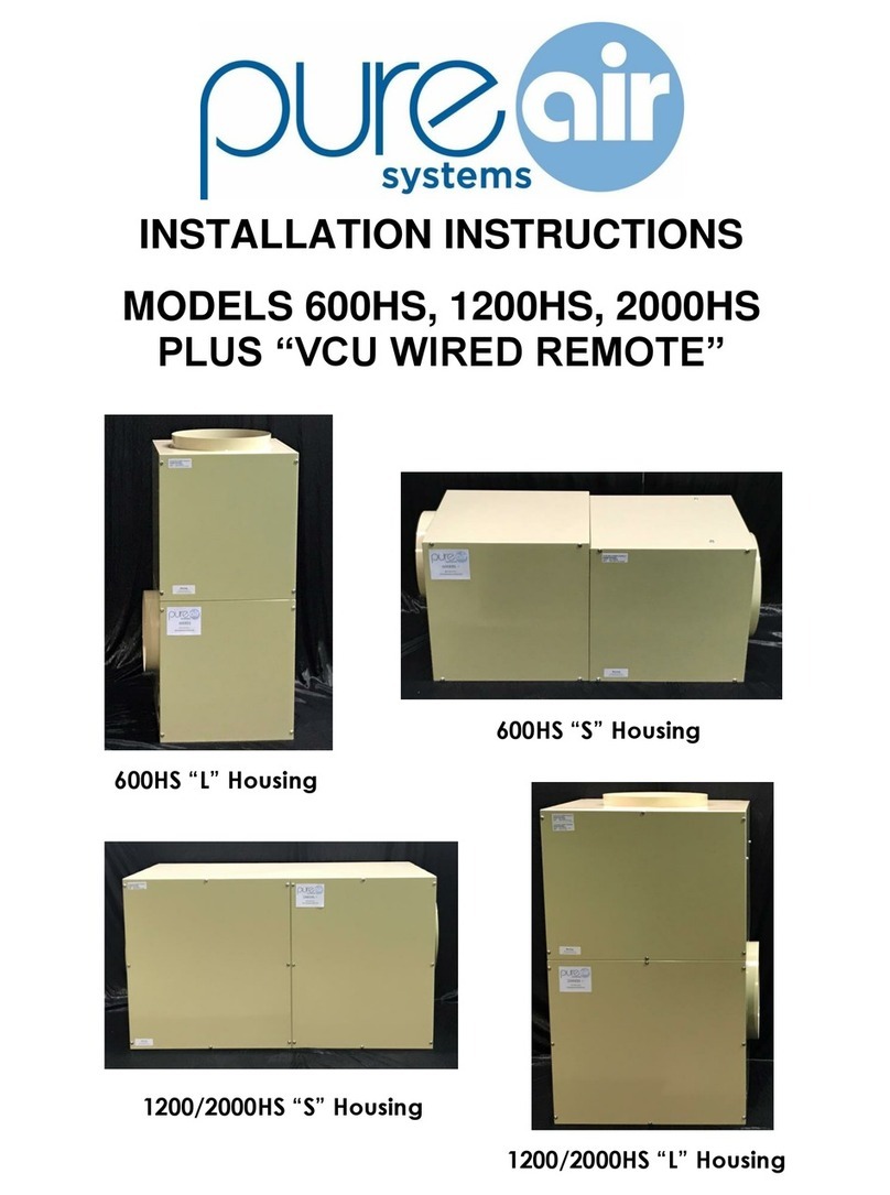
600HS “S”Housing
600HS “L”Housing
INSTALLATION INSTRUCTIONS
MODELS 600HS, 1200HS, 2000HS PLUS
“HVAC”
1200/2000HS “L”Housing
1200/2000HS “S”Housing

2
STEP1.
STEP2.
STEP3.
STEP4.
STEP5.
STEP6.
STEP7.
STEP8.
ASSEMBLY INSTRUCTIONS
HVAC VERSION
Unpack your unit and remove all packing from the blower and motor
assembly.
Remove both housing access doors.
VERY IMPORTANT NOTE! MAKE SURE THE BLOWER WHEEL SPINS
FREELY.
For 1200/2000 "S" version units skip to Step 8.
From the filter section, remove the wire framed pre-filter and carbon filter.
Locate the two HEPA filter holding strips that also act as a tray for the
carbon filter and pre-filter. Remove the two hex nuts and associated
screws on both holding trays and remove the trays from the housing.
Remove the hex head screws that are in the gasket material on the
BOTTOM (motor) section of your unit. The BOTTOM & TOP (filter)
sections are symmetrical, so they can be rotated 360 degrees so the
discharge can be pointed in four different directions to accommodate
any installation configuration. This allows for best directional location
for the TOP section filter access door. MAKE SURE THE DISCHARGE
DIRECTION IS CORRECT FOR YOUR APPLICATION BEFORE
ASSEMBLING. Align the sections as desired. Place the TOP section on
the BOTTOM section, align the holes and tighten the hex head screws.
Insert HEPA filter. BE CAREFUL TO NOT PUNCTURE THE HEPA MEDIA.
The gasket should be toward the motor unit. Center the gasket over the
knife-edges so that it is even on all four sides. Replace the two HEPA
holding trays.
Remove the wrapping from the carbon filter and slide the carbon filter and
pre-filter back into the trays and replace the access door.
Please look at the attached "typical installation" drawings. The inlet duct should be
connected to the main return air duct leading to the heating/cooling system, and the
discharge duct should be connected to the point where the return air duct enters the
heating/cooling fan area.
ALWAYS INSTALL THIS SYSTEM IN A BY-PASS CONFIGURATION.

3
1.)
2.)
3.)
4.)
5.)
6.)
7.)
MATERIALS NEEDED FOR COMMON HVAC INSTALLATIONS
Section of 12" (14" for 1200/2000 units) diameter sheet metal (recommended) or
flex duct. You will need 3' to 6' for most installations.
Section of 10" (14" for 1200/2000 units) diameter sheet metal (recommended) or
flex duct. You will need 6" to 24" for most installations.
12" collar (14" for 1200/2000 units) for connection to return air duct.
10" collar (14" for 1200/2000 units) for connection to fan return side of HVAC unit.
4" by 18" ( 4" by 24" for 1200/2000 units) piece of sheet metal for Air Scoop. Or a
prefabricated damper. This is recommended to be installed with every unit.
Sheet metal screws, duct tape or metal tape. 12 gauge electrical wire for power to
unit.
Thermostat wire.
INSTALLATION OF THE DUCTING
Select the proper location for the attachment of the inlet and discharge ducts.
Try to keep a minimum of 6 feet between the inlet and discharge openings. This
will prevent the Pure Air Systems’ filtration unit from recycling the same air. Cut
the openings in the existing return air duct. We recommend an air scoop be
placed inside of the return air duct so that it directs air into the inlet duct of your
filtration system. You can use a damper as an air scoop. Make sure the damper is
angled to direct the air from the return air duct into the inlet duct of your filtration
system.
Use sheet metal screws, duct tape or aluminum tape to attach the duct sections
to the collars on the inlet of the unit and the air return. Make sure there are no air
leaks.Repeat this same procedure for the discharge duct. Make sure all
connections are tight and taped.
ELECTRICAL WIRING & POWER CONNECTION
***WIRING FROM 240 VOLT***
For 240 volt operation you will need to cut the "black jumper wire" that connects pin 1
to pin 2 on the 5 pin white power connector attached to the back end of the motor.
FAILURE TO COMPLETE THIS WIRING CHANGE WILL
RESULT IN DAMAGE TO THE MOTOR.

4
NOTE: ALWAYS FOLLOW ELECTRICAL CODES FOR YOUR AREA. We
recommend a dedicated 15 amp service for all of our air filtration systems. The
conduit connector is designed for EMT conduit or Romex cable. Wire the
black, white and green (ground) wires through the conduit connector to the
black, white and green wires inside the unit.
CONTROL WIRING FROM THE THERMOSTAT
Your air filtration system is designed and programmed to respond to the
thermostat and run in-sync with the HVAC system. When the thermostat is in
the auto mode the unit will ramp up to high speed when the thermostat calls
for heating or cooling. Once the demand is met, the unit will shut off when the
HVAC unit shuts off. If the thermostat is in the On mode, the unit will ramp up
to high speed until HVAC demand is met and then ramp down to one of four
volume settings on the Tap Board. For best performance set the thermostat
setting to the On mode. This will allow both the HVAC system and air filtration
unit to run all the time, moving air through the house. This will maintain a
more consistent temperature while continually filtering the air.
WIRING TO TERMINAL STRIP
There are 6 screw terminals on the terminal strip. The indicator label below the
strip shows the location of the wires for proper installation. The color-coding is
as follows: From left to right; Black & Brown (24 VAC transformer) positive
and common, White (W1/W2) heat, Yellow (Y1/Y2) cool, Green fan, Red 24V
positive. Wire from the transformer or from the corresponding contact block
or terminals in the HVAC unit to the terminal block in the unit. Make sure all
connections are tight. The thermostat control wires should be pulled through
the 7/8" finishing plug located next to the conduit connector.

5
TWO-STAGE COOLING---TWO-STAGE HEATING: Many HVAC systems
incorporate a two-stage compressor for cooling and two-stage heating systems.
If this is the case, the HVAC system will usually run at 50% of volume in the first
stage mode and then ramp up to 100% of volume in the second stage mode.
This unit also recognizes these variations. When wiring this unit to a two-stage
cooling system you will need to take the Y/Y2 wire from the thermostat/HVAC
unit and wire this to the yellow position on the terminal strip in the unit. When
wiring this unit to a two-stage heating system you will need to take the W/W2
wire from the thermostat/HVAC unit and wire this to the white position on the
terminal strip in the unit.
NEVER CHANGE THE TAP BOARD SETTINGS WHEN THE MOTOR IS RUNNING
TAP BOARD SELECTOR VOLUME CONTROL
The tap board is mounted on the adapter panel at the factory. The black wire
from the terminal strip is connected to the 24 VAC tap on the board. This should
ALWAYS be connected. Please check this connection. The other four taps on
the board are for speed/volume settings for the blower in the off-demand or fan
only running cycles (low, med, high, max). The twin orange wires from the
harness are connected to the low tap from the factory. This means in an off-
demand or fan only (non-demand) mode the blower will run at 30% of volume.
The medium setting is 50% of volume, the high setting is 80% of volume and the
max setting is 100% of volume. For best operational performance and lowest
operating costs we recommend either the low or medium settings. NOTE: In any
case, the lowest tap board setting can be no higher than the lowest running
volume of the variable speed HVAC system.
TESTING THE UNIT
To ensure that all the control wiring is correct, cycle through the heat and
cool settings on the thermostat and make sure the air filtration unit runs at the
correct volumes in conjunction with the HVAC unit. Don't forgetifyouwantto
makeanadjustment on the tap board you must first turn off the unit before
switching to another setting. If you have any problems or questions please
call us at: 800-869-8025.
ODOR ADSORPTION MODELS
All Odor Adsorption models are identical to the regular models except there is
no HEPA filter. In-lieu of the HEPA filter there is a carbon cannister.

6

7
General Residential Guidelines
for Replacing Filters
•Prefilter 3 months
•Carbon filter every year
•HEPA filter 2.5 to 3 years
6115 Guion Rd.
Indianapolis, IN 46254
800.869.8025 or 317.291.4341
Fax 317.291.4381
pas@pureairsystems.com

8
General Commercial Guidelines
for Replacing Filters
•Prefilter once a month
•Carbon filter every 6 months
•HEPA filter once a year
6115 Guion Rd.
Indianapolis, IN 46254
800.869.8025 or 317.291.4341
Fax 317.291.4381
pas@pureairsystems.com

9

10
6115 Guion Rd.
Indianapolis, IN 46254
800.869.8025
317.291.4341
e-mail: pas@pureairsystems.com
www.pureairsystems.com
FILTER MAINTENANCE
WARNING
(Before changing any filters always turn power off to unit by switching the lighted rocker
switch located on the discharge or motor section of the unit to the off or down position.)
PREFILTER: (change every 3 to 4 months unless used in commercial applications.)
1.) Ring panel prefilter is located on top or next to the carbon filter. Simply slide the prefilter out and replace with new prefilter. Make sure white side is
facing up or toward the airflow. Replace filter door and turn lighted rocker switch back to the on or up position.
CARBON FILTER: (change every 9 to 12 months unless used in commercial applications.)
1.) Carbon filter is located just under the prefilter or between prefilter and HEPA filter. Some housings you’ll have to remove prefilter before you can
remove and replace carbon filter. Replace prefilter on top of carbon filter. Replace filter door and turn lighted rocker switch back to the on or up position.
HEPA FILTER: (change every 2.5 to 3 years unless used in commercial applications.)
1.) Remove prefilter and carbon filter.
2.) Remove nuts and bolts (two on each side) that attach hold down channels. On some housings you’ll need to loosen the set screws (top and bottom)
and remove the bolts to the compression brackets. Remove both channels and or brackets. Lift HEPA filter out of housing.
3.) Carefully place new HEPA filter back in housing. Lift and position HEPA filter with gasket side facing down sitting evenly on metal knife edge on all four
sides.
4.) Replace channels and or brackets with bolts, nuts or set screws to their original locations and tighten them. Replace carbon and prefilter.
5.) Replace filter door and turn lighted rocker switch back to the on or up position.
Other manuals for 600HS
2
This manual suits for next models
2
Table of contents
Other PureAir Air Conditioner manuals
Popular Air Conditioner manuals by other brands

Airwell
Airwell Dakota DCI Series Service manual

Sanyo
Sanyo SAP-CMRV1923GJH Technical & service manual

INVENTOR
INVENTOR Neo N2UVO-09 user manual

Mitsubishi Electric
Mitsubishi Electric MSZ-DM25VA operating instructions

Hisense
Hisense AUC-18UX4SGAA Instruction and installation manual

Daikin
Daikin FFQ25B9V1B Operation manual