PureLink VIP-200 II Quick Start Guide V1.0
4
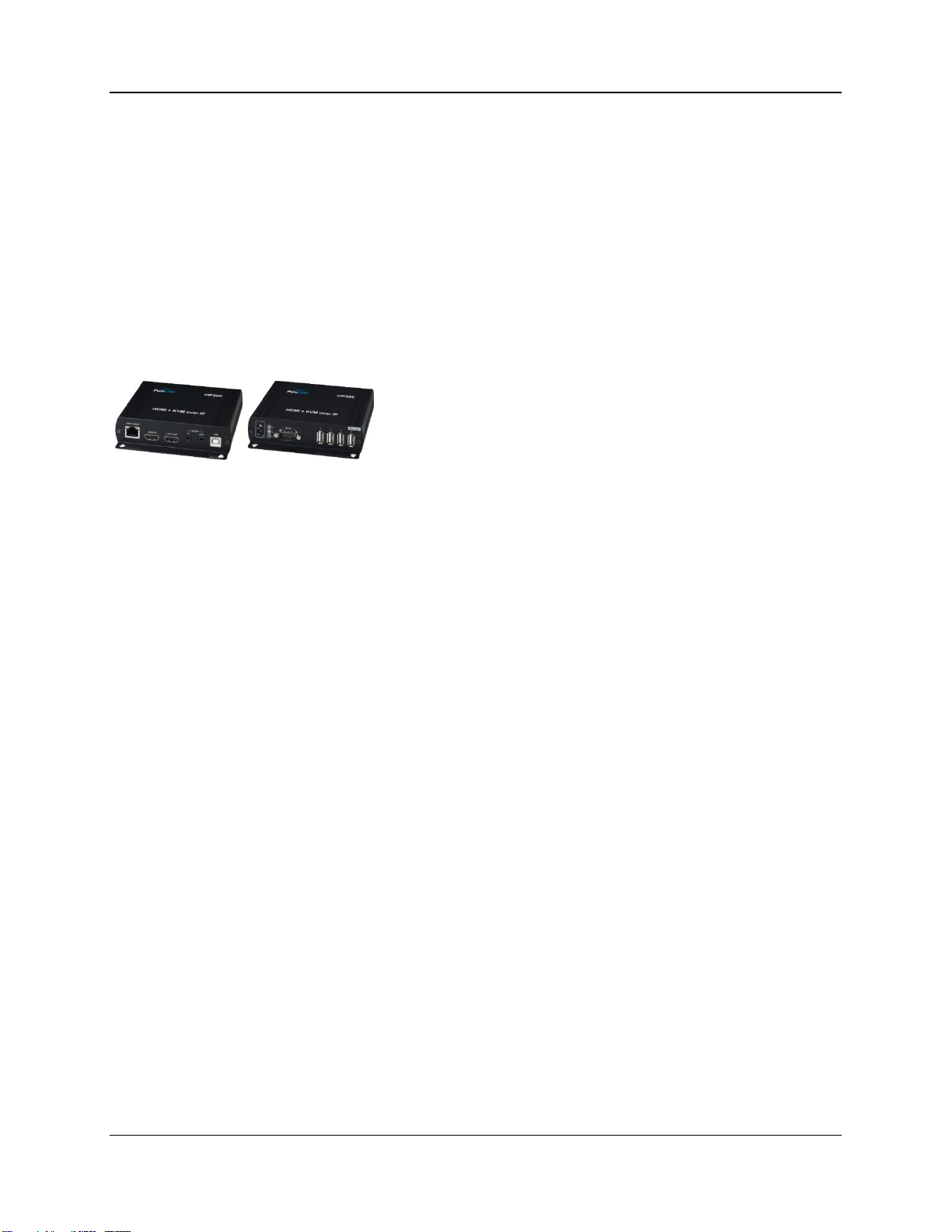
Overview
The VIP200 II series allows point-to-point (extender), point-to-many (distribution), many-to-
point (switching), and many-to-many (matrix) configurations. The VIP200 II series is set to
work out of the box as a point-to-point, or point-to-many system, no configuration is
necessary. For point to many configurations, simply plug them together through a network
switch using CAT5e or better cable.
The VIP200 II series covers all three modes of addressing.
Auto IP Addressing
The VIP200 II system default configuration provides automatic IP addressing in the
169.254.xxx.xxx range. The Auto IP method provides instant and easy setup and operation of
the VIP200 II devices when a specific manual IP address method is not required, and DHCP
is not required.
Manual IP Addressing (recommended)
The VIP200 II device IP addresses can be configured manually. Manual IP addressing is
utilized when the network is not DHCP, and the Auto IP range 169.254.xxx.xxx does not work
with the current network, or the intended design. These settings are normally done prior to
adding on to a network. Please see the ‘Setting Devices for Manual IP Addressing” in this
manual.
DHCP Addressing
The VIP200 II device IP addresses can be configured to accept IP addresses using DHCP.
Using our simple software application to identify the devices, you can then access their built-
in web page interface to change the devices to DHCP IP mode.
NOTE: Because transmitters create continuous streaming traffic of video on the network, it is
recommended when possible to create your IP video network independent of your data
network. Use of gigabit switches with jumbo frame and IGMP support are required for both
independent IP video networks, and cases where IP video systems are included within your
data network.