Western FCB Series Service manual

INSTALLATION, USE AND MAINTENANCE MANUAL
FCB
FAN COANDA BOOSTER
SERIES


INDEX
!
1- INTRUDUCTION...................................................................................................................................... 4
2-RECEIVING .............................................................................................................................................. 5
3-INSTALLATION INSTRUCTIONS ............................................................................................................. 5
3.1-Positioning.......................................................................................................................................... 5
3.2-Fixing the unit to the true ceiling.......................................................................................................... 5
3.3-Hydraulic connections ......................................................................................................................... 6
3.4-Condensate drainage ......................................................................................................................... 7
3.5-False-ceiling installation ...................................................................................................................... 7
3.6-Slots position regulation .................................................................................................................... 12
4- Electrical connections ............................................................................................................................ 13
5- Maintenance .......................................................................................................................................... 14
5.1-Ordinary maintenance (every 6 months) ........................................................................................... 14
5.2-Extraordinary maintenance ............................................................................................................... 14
!

FCB
4
False ceiling
Supply grille
90° silenced plenum Unit body
1- INTRUDUCTION
This manual contains the instructions for a right installation and maintenance of the unit. If these instructions
will be not respected, the manufacturer will not be responsible of damages to people, things and to the units.
The installation and the maintenance must be done by qualified technician. During the operation, the technician
must respect all the safety rules (protective clothes for hands and eyes, …).
Before to work in the units, switch-off the power supply and be sure that nobody can switch-on it for mistake.
Use only originals of approved spare parts.
The units contain rotary components: after switching-off the power supply, we recommend to wait 5 minutes
before to open the inspection panels, to give time to fan to stop.
The units are designed for residential and commercial air-conditioning, not exposed to rain, ice or extreme
temperatures, not dusty and not explosive environment: the manufacturer will not be responsible in case of
not correct applications.

5
2-RECEIVING
After receiving, clean the unit from all the packing components. If the units looks damaged or not completed,
don’t go on with the installation. Check in the label that the units received is the same of the ordered code.
Claims must be submitted by writing within 8 days from receiving.
3-INSTALLATION INSTRUCTIONS
The units are designed to be installed under-ceiling. Dimensions of the grille and of the unit are right to be
installed in continuous ceiling or in 600x600mm modular block ceiling. Special dimensions can be requested
to the manufacturer in case of different modular block ceiling dimensions.
3.1-Positioning
The unit is designed to supply air with Coanda effect (according to this effect, air flow is horizontal, and very
closed to the ceiling). For this reason, the position of the unit and of the room furnishing (lamps,..) must be
studied not to stop the air flow.
The position of the unit must be evaluated considering also the threw distance of the unit (refer to technical
manual).
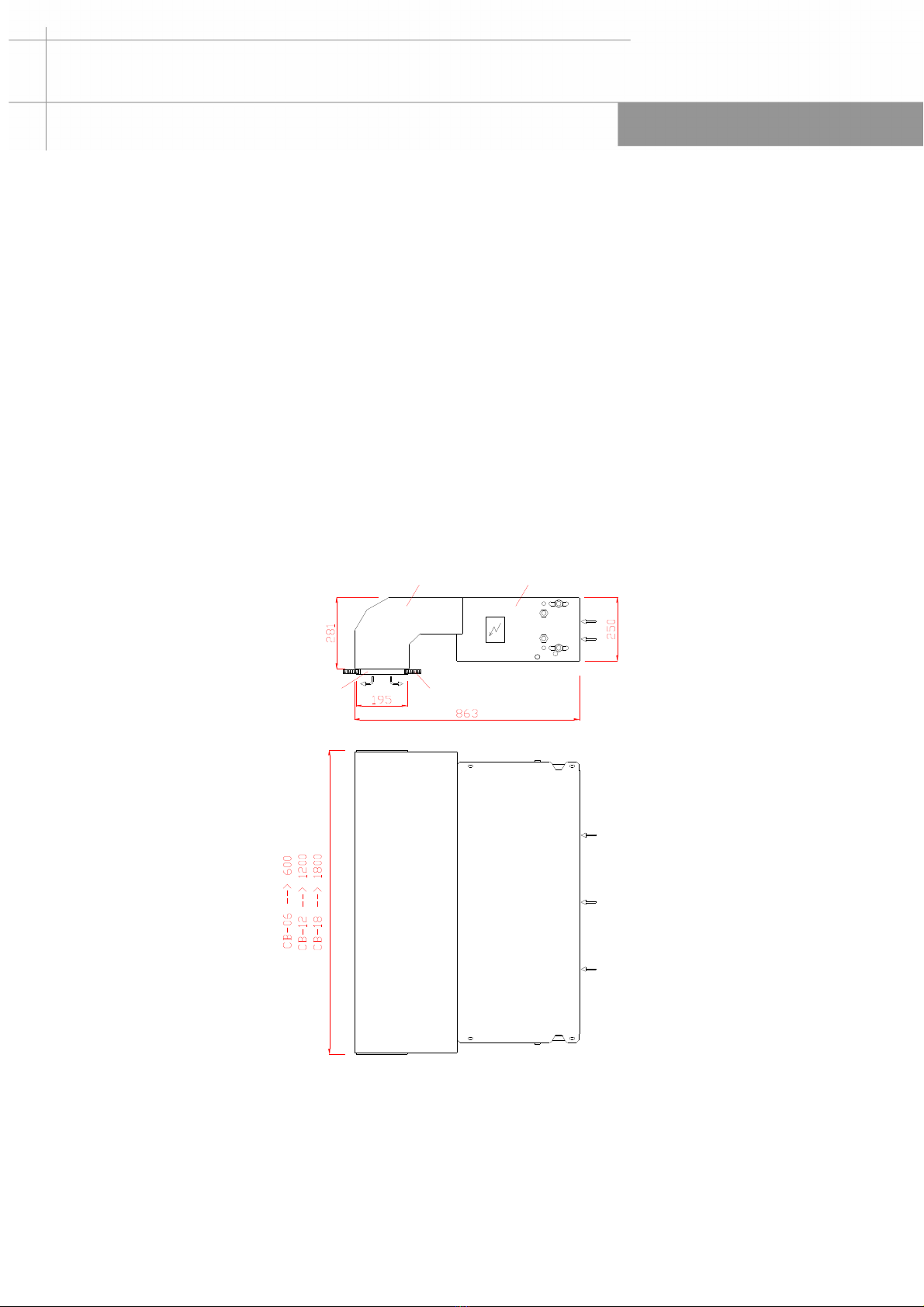
Respect the minimum distance needed for maintenance, (see dimensional drawings).
3.2-Fixing the unit to the true ceiling
First of all, be sure that the true ceiling and the components used are able to carry the weight of the units.
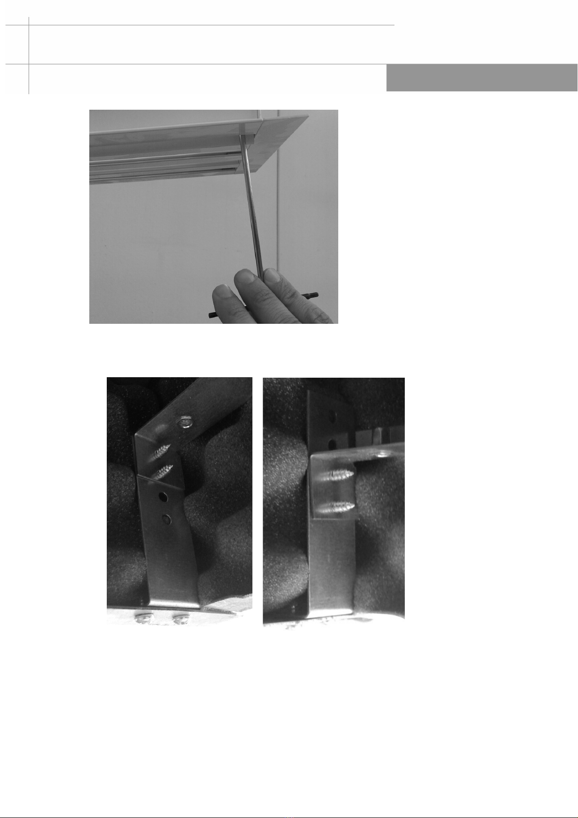
Fix the units to the true ceiling using the 20x10 holes in the right and left flanks. Units sizes 18 has also holes
20x10 in the plenum. For more information regarding the fixing holes, see dimensional drawings.
We suggest to install the units using M8 treaded bar and to block it using nuts and washers. Even if the fans
have very low vibrations, we suggest to use rubber anti-vibrations.

FCB
6
Before to close the counter-nuts, be sure that the unit is perfectly horizontal, without inclination.
3.3- Hydraulic connections
Connect water pipes to the unit with attention, without create damages to the coil or to the valve. The pipes
weight must be supported by brackets and not by coil connections.
Respect IN/OUT label near the connections.
If the unit is supplied with valve, install the auxiliary drain pan (to be fixed with two screws) and seal with
silicone.
Silicone Screw
Screw
Auxiliary drain pan
We suggest to install manual shut-off valve in all water connections, because in this way will be easier to do
supplementary maintenance in the coil
When the pipes will be filled with water, eliminate air from the coil using the valve positioned near the
connection (indicated with labels in the flank of the unit). In case of freezing risk, add anti-freezing additive in
the pipes or discharge the pipes during winter.

7
3.4-Condensate drainage
The condensate drainage pipes must have a sufficient inclination to the bottom; if it’s not possible, install a
condensate drainage pump.
To prevent the penetration of odors from outside, we recommend forming a siphon in the line.
Condensate drainage
3.5-False-ceiling installation
To install the grille, must be made a rectangular hole in the false ceiling of the following dimensions:
FCB-06
FCB-12
FCB-18
A
175
175
175
B
560
1160
1760
Insert the grille in the rectangular hole from the bottom side and fix it with the M4 screws.

FCB
8
Installation in standard false-ceiling (lateral view)
Installation in standard false-ceiling (frontal view)
Installation in modular block false-ceiling (lateral view)

9
Installation in modular block false-ceiling (frontal view)
To fix the grille, do as follows :
- Push the four C elements in the four corners of the grille and place the M4 screw as in picture.
Fix the screw with O-ring.
- Using esagonal screw-driver, fix M4 screws on the threaded brackets of the plenum

FCB
10
- According to the thikness of false-ceiling, the bracket of the plenum can be positioned in higer or
lower position
To allow accessibility to the unit, a removable inspection panel is needed in the false-ceiling, as
shown in the following drawings.

11
FCB-06
FCB-12
FCB-18
L (mm)
1300
1560
2080

FCB
12
3.6-Slots position regulation
The grille has 4 slots, that can be manually regulated to have one or two air flow direction. Usually, after the
first regulation, the same slot position can be used in cooling and heating mode : so no other manual
adjustment is required.
Slot position: one air flow direction (coanda effect)
Slot position: two air flow direction (coanda effect)

13
In heating mode, if false-ceiling is more than 3m high, may be necessary to change slots position, in order to
have vertical air flow.
Slot position: vertical air flow
4- Electrical connections
Before to work on the electrical wiring, switch-off the power supply and be sure that nobody can switch-on it
for mistake. Check that the available power supply (voltage, number of phases and frequency) is the same of
the label motor. Install a thermic breaker switch or a fuse switch to protect the unit.
Motor electric wiring

FCB
14
5- Maintenance
5.1-Ordinary maintenance (every 6 months)
Filter cleaning : according to the pollution level of the environment, filter can be cleaned more often than usual..
Standard filter is made in polypropylene and is washable with warm water. If during the inspection the filter
looks damaged, must be replaced with a new one. To remove the filter, turn the block and slip-off the filter from
the bottom.
Filter
General checks : check that electrical and hydraulic connections and all screws are well closed. Check that
the casing is not damaged (by rust or corrosion) and that there aren’t strange vibrations or noise when the fan
is running.
5.2-Extraordinary maintenance
To access to the internal components of the unit (fan and coil) , remove the bottom panel, screwing-off the
screws as in the picture below.
Screws
Removable bottom panel

15
To remove the fan-deck, screw-off the screws as in the picture below.
Screws to remove the fan-deck.
To remove the drain pan and the coil, screw-off the screws as in the picture below.
Screw to remove drain pan and coil

FCB
16
NOTE:
________________________________________________
________________________________________________
________________________________________________
________________________________________________
________________________________________________
________________________________________________
________________________________________________
________________________________________________
________________________________________________
________________________________________________
________________________________________________
________________________________________________
________________________________________________
________________________________________________
________________________________________________
________________________________________________
________________________________________________
________________________________________________
________________________________________________
________________________________________________
________________________________________________

17
________________________________________________
________________________________________________
________________________________________________
________________________________________________
________________________________________________
________________________________________________
________________________________________________
________________________________________________
________________________________________________
________________________________________________
________________________________________________
________________________________________________
________________________________________________
________________________________________________
________________________________________________
________________________________________________
________________________________________________
________________________________________________
________________________________________________
________________________________________________
________________________________________________

FCB
18
________________________________________________
________________________________________________
________________________________________________
________________________________________________
________________________________________________
________________________________________________
________________________________________________
________________________________________________
________________________________________________
________________________________________________
________________________________________________
________________________________________________
________________________________________________
________________________________________________
________________________________________________
________________________________________________
________________________________________________
________________________________________________
________________________________________________


MIU.FCB.GB.001.07/2018
This manual suits for next models
3
Table of contents
Popular Extender manuals by other brands

SolidRF
SolidRF BP5 user manual

Clayton Power
Clayton Power LEAB CLP 600 user manual

Kindermann
Kindermann 7488 000 080 operating instructions

AMG
AMG AMG4743Bx-SF instruction manual

Linksys
Linksys WRE54G - Wireless-G Range Expander Repeater user guide

Fortinet
Fortinet FortiExtenderVehicle 211F quick start guide