QCT QuantaGrid Series User manual

Version: 1.0
QuantaGrid Series
D51PH-1ULH
Hybrid Scale-Out / High Computing
Storage Server
Service Guide

I
TABLE OF CONTENTS
About the System
Introduction. . . . . . . . . . . . . . . . . . . . . . . . . . . . . . . . . . . . . . . . . . . . . . . . . 1-1
Package Contents. . . . . . . . . . . . . . . . . . . . . . . . . . . . . . . . . . . . . . . . . . . . 1-4
A Tour of the System . . . . . . . . . . . . . . . . . . . . . . . . . . . . . . . . . . . . . . . . . 1-5
System Overview . . . . . . . . . . . . . . . . . . . . . . . . . . . . . . . . . . . . . . . . 1-5
System Front View . . . . . . . . . . . . . . . . . . . . . . . . . . . . . . . . . . . . . 1-7
Front Control Panel . . . . . . . . . . . . . . . . . . . . . . . . . . . . . . . . . . . . 1-7
System Rear View . . . . . . . . . . . . . . . . . . . . . . . . . . . . . . . . . . . . . . 1-9
Rear I/O . . . . . . . . . . . . . . . . . . . . . . . . . . . . . . . . . . . . . . . . . . . . . . 1-9
PSU View . . . . . . . . . . . . . . . . . . . . . . . . . . . . . . . . . . . . . . . . . . . .1-10
LED Definitions . . . . . . . . . . . . . . . . . . . . . . . . . . . . . . . . . . . . . . . . .1-11
Front SAS/SATA HDD/SSD LED. . . . . . . . . . . . . . . . . . . . . . . . . .1-11
LAN Port LED. . . . . . . . . . . . . . . . . . . . . . . . . . . . . . . . . . . . . . . . .1-11
BMC Management Port LED. . . . . . . . . . . . . . . . . . . . . . . . . . . .1-12
Installing Hardware
Safety Measures . . . . . . . . . . . . . . . . . . . . . . . . . . . . . . . . . . . . . . . . . . . . . 2-1
Power Supply Unit . . . . . . . . . . . . . . . . . . . . . . . . . . . . . . . . . . . . . . . . . . . 2-2
Removing the Redundant Power Supply Unit . . . . . . . . . . . . . . . . 2-2
Installing the Power Supply Unit . . . . . . . . . . . . . . . . . . . . . . . . . . . 2-3
HDD Tray . . . . . . . . . . . . . . . . . . . . . . . . . . . . . . . . . . . . . . . . . . . . . . . . . . . 2-4
Releasing the HDD Tray. . . . . . . . . . . . . . . . . . . . . . . . . . . . . . . . . . . 2-4
Securing a HDD Tray . . . . . . . . . . . . . . . . . . . . . . . . . . . . . . . . . . . . . 2-5
Hot-plug HDD . . . . . . . . . . . . . . . . . . . . . . . . . . . . . . . . . . . . . . . . . . . . . . . 2-6
Hot-Plug HDD Assembly Overview . . . . . . . . . . . . . . . . . . . . . . . . . 2-6
Removing a HDD carrier and HDD from the HDD tray . . . . . . . . 2-7
Installing a HDD carrier with HDD to HDD tray. . . . . . . . . . . . . . . 2-9
Top Cover. . . . . . . . . . . . . . . . . . . . . . . . . . . . . . . . . . . . . . . . . . . . . . . . . .2-11
Removing the Top Cover. . . . . . . . . . . . . . . . . . . . . . . . . . . . . . . . .2-11

II
Installing the Top Cover. . . . . . . . . . . . . . . . . . . . . . . . . . . . . . . . . .2-11
Fan Module . . . . . . . . . . . . . . . . . . . . . . . . . . . . . . . . . . . . . . . . . . . . . . . .2-13
Removing a Fan Module . . . . . . . . . . . . . . . . . . . . . . . . . . . . . . . . .2-13
Installing a Fan Module . . . . . . . . . . . . . . . . . . . . . . . . . . . . . . . . . .2-14
Memory Modules . . . . . . . . . . . . . . . . . . . . . . . . . . . . . . . . . . . . . . . . . . .2-16
General Guidelines. . . . . . . . . . . . . . . . . . . . . . . . . . . . . . . . . . . . . .2-16
Memory Population Support . . . . . . . . . . . . . . . . . . . . . . . . . . . . .2-16
Removing a Memory Module . . . . . . . . . . . . . . . . . . . . . . . . . . . . .2-16
Installing a Memory Module . . . . . . . . . . . . . . . . . . . . . . . . . . . . . .2-17
Processor Heat Sink . . . . . . . . . . . . . . . . . . . . . . . . . . . . . . . . . . . . . . . . .2-19
Removing a Processor Heat Sink. . . . . . . . . . . . . . . . . . . . . . . . . .2-19
Installing a Processor Heat Sink. . . . . . . . . . . . . . . . . . . . . . . . . . .2-19
Processor . . . . . . . . . . . . . . . . . . . . . . . . . . . . . . . . . . . . . . . . . . . . . . . . . .2-21
Removing the Processor . . . . . . . . . . . . . . . . . . . . . . . . . . . . . . . . .2-21
Installing the Processor . . . . . . . . . . . . . . . . . . . . . . . . . . . . . . . . . .2-22
Expansion Card. . . . . . . . . . . . . . . . . . . . . . . . . . . . . . . . . . . . . . . . . . . . .2-24
Removing a Riser Assembly . . . . . . . . . . . . . . . . . . . . . . . . . . . . . .2-24
Installing a Riser Assembly . . . . . . . . . . . . . . . . . . . . . . . . . . . . . . .2-25
OCP Mezzanine Board. . . . . . . . . . . . . . . . . . . . . . . . . . . . . . . . . . . . . . .2-26
Removing a OCP Mezzanine Board. . . . . . . . . . . . . . . . . . . . . . . .2-26
Installing an OCP Mezzanine Board . . . . . . . . . . . . . . . . . . . . . . .2-27
BIOS
BIOS Setup Utility . . . . . . . . . . . . . . . . . . . . . . . . . . . . . . . . . . . . . . . . . . . . 3-1
Operation. . . . . . . . . . . . . . . . . . . . . . . . . . . . . . . . . . . . . . . . . . . . . . . 3-1
Setup Page Layout . . . . . . . . . . . . . . . . . . . . . . . . . . . . . . . . . . . . . . . 3-1
Entering BIOS Setup. . . . . . . . . . . . . . . . . . . . . . . . . . . . . . . . . . . . . . 3-1
Keyboard Commands . . . . . . . . . . . . . . . . . . . . . . . . . . . . . . . . . . . . 3-2
Menu Selection Bar . . . . . . . . . . . . . . . . . . . . . . . . . . . . . . . . . . . . . . 3-3
Server Platform Setup Utility Screens. . . . . . . . . . . . . . . . . . . . . . . 3-4
Main Screen. . . . . . . . . . . . . . . . . . . . . . . . . . . . . . . . . . . . . . . . . . . . . 3-4

III
Advanced Screen . . . . . . . . . . . . . . . . . . . . . . . . . . . . . . . . . . . . . . . . 3-5
IntelRCSetup Screen . . . . . . . . . . . . . . . . . . . . . . . . . . . . . . . . . . . 3-7
Server Management Screen . . . . . . . . . . . . . . . . . . . . . . . . . . . . . . . 3-8
Boot Options Screen . . . . . . . . . . . . . . . . . . . . . . . . . . . . . . . . . . . .3-10
Security Screen . . . . . . . . . . . . . . . . . . . . . . . . . . . . . . . . . . . . . . . . .3-11
Exit Screen . . . . . . . . . . . . . . . . . . . . . . . . . . . . . . . . . . . . . . . . . . . . .3-12
Loading BIOS Defaults. . . . . . . . . . . . . . . . . . . . . . . . . . . . . . . . . . .3-14
BIOS Update Utility. . . . . . . . . . . . . . . . . . . . . . . . . . . . . . . . . . . . . . . . . .3-15
BIOS Update Utility. . . . . . . . . . . . . . . . . . . . . . . . . . . . . . . . . . . . . .3-15
AFULNX: v2.39. . . . . . . . . . . . . . . . . . . . . . . . . . . . . . . . . . . . . . . .3-15
ME Region Update . . . . . . . . . . . . . . . . . . . . . . . . . . . . . . . . . . . .3-15
BIOS Setting Utility . . . . . . . . . . . . . . . . . . . . . . . . . . . . . . . . . . . .3-16
BIOS Revision . . . . . . . . . . . . . . . . . . . . . . . . . . . . . . . . . . . . . . . .3-16
Clear CMOS . . . . . . . . . . . . . . . . . . . . . . . . . . . . . . . . . . . . . . . . . . . .3-16
Clear Password . . . . . . . . . . . . . . . . . . . . . . . . . . . . . . . . . . . . . . . . .3-16
BIOS Update Via BMC Instructions (Optional) . . . . . . . . . . . . . .3-17
Server Management. . . . . . . . . . . . . . . . . . . . . . . . . . . . . . . . . . . . . . . . .3-18
Console Redirection. . . . . . . . . . . . . . . . . . . . . . . . . . . . . . . . . . . . .3-18
Serial Configuration Settings . . . . . . . . . . . . . . . . . . . . . . . . . . .3-18
Keystroke Mapping . . . . . . . . . . . . . . . . . . . . . . . . . . . . . . . . . . .3-18
Reset. . . . . . . . . . . . . . . . . . . . . . . . . . . . . . . . . . . . . . . . . . . . . . . .3-19
Limitations . . . . . . . . . . . . . . . . . . . . . . . . . . . . . . . . . . . . . . . . . . .3-19
Interface to Server Management (Optional) . . . . . . . . . . . . . .3-20
Network BIOS Support . . . . . . . . . . . . . . . . . . . . . . . . . . . . . . . . . .3-20
PXE Boot. . . . . . . . . . . . . . . . . . . . . . . . . . . . . . . . . . . . . . . . . . . . .3-20
Checkpoints. . . . . . . . . . . . . . . . . . . . . . . . . . . . . . . . . . . . . . . . . . . .3-20
Debug Header. . . . . . . . . . . . . . . . . . . . . . . . . . . . . . . . . . . . . . . .3-20
BMC
Server Management Software . . . . . . . . . . . . . . . . . . . . . . . . . . . . . . . . . 4-1
Server System Overview . . . . . . . . . . . . . . . . . . . . . . . . . . . . . . . . . . 4-1
BMC Key Features and Functions . . . . . . . . . . . . . . . . . . . . . . . . . . 4-1

IV
Power System . . . . . . . . . . . . . . . . . . . . . . . . . . . . . . . . . . . . . . . . . . . 4-1
Front Panel User Interface . . . . . . . . . . . . . . . . . . . . . . . . . . . . . . . . 4-2
Power Button . . . . . . . . . . . . . . . . . . . . . . . . . . . . . . . . . . . . . . . . . 4-2
ID Button . . . . . . . . . . . . . . . . . . . . . . . . . . . . . . . . . . . . . . . . . . . . . 4-2
LEDs . . . . . . . . . . . . . . . . . . . . . . . . . . . . . . . . . . . . . . . . . . . . . . . . . 4-2
LAN Interface. . . . . . . . . . . . . . . . . . . . . . . . . . . . . . . . . . . . . . . . . . . . 4-2
Session and User . . . . . . . . . . . . . . . . . . . . . . . . . . . . . . . . . . . . . . 4-3
Serial Over LAN. . . . . . . . . . . . . . . . . . . . . . . . . . . . . . . . . . . . . . . . . . 4-3
Time Sync. . . . . . . . . . . . . . . . . . . . . . . . . . . . . . . . . . . . . . . . . . . . . . . 4-3
SEL. . . . . . . . . . . . . . . . . . . . . . . . . . . . . . . . . . . . . . . . . . . . . . . . . . . . . 4-3
Platform Event. . . . . . . . . . . . . . . . . . . . . . . . . . . . . . . . . . . . . . . . . . . 4-3
Platform Event Filter. . . . . . . . . . . . . . . . . . . . . . . . . . . . . . . . . . . . 4-3
BMC Firmware Update . . . . . . . . . . . . . . . . . . . . . . . . . . . . . . . . . . . 4-4
DOS Recovery Utility . . . . . . . . . . . . . . . . . . . . . . . . . . . . . . . . . . . 4-4
WebUI Update . . . . . . . . . . . . . . . . . . . . . . . . . . . . . . . . . . . . . . . . 4-4
BMC Recovery . . . . . . . . . . . . . . . . . . . . . . . . . . . . . . . . . . . . . . . . . . . . . . . 4-5
Recovery Process in DOS System . . . . . . . . . . . . . . . . . . . . . . . . . . 4-5
Recovery Process in Linux System . . . . . . . . . . . . . . . . . . . . . . . . . 4-5
Recovery Process in Windows System . . . . . . . . . . . . . . . . . . . . . . 4-5
SMASH . . . . . . . . . . . . . . . . . . . . . . . . . . . . . . . . . . . . . . . . . . . . . . . . . . . . . 4-6
System Level Commands . . . . . . . . . . . . . . . . . . . . . . . . . . . . . . . 4-7
BMC Information . . . . . . . . . . . . . . . . . . . . . . . . . . . . . . . . . . . . .4-11
Web Graphical User Interface (GUI) for ESMS. . . . . . . . . . . . . . . . . . .4-13
Using the Web GUI. . . . . . . . . . . . . . . . . . . . . . . . . . . . . . . . . . . . . .4-13
Login . . . . . . . . . . . . . . . . . . . . . . . . . . . . . . . . . . . . . . . . . . . . . . . . . .4-13
Dashboard. . . . . . . . . . . . . . . . . . . . . . . . . . . . . . . . . . . . . . . . . . . . .4-14
Device Information. . . . . . . . . . . . . . . . . . . . . . . . . . . . . . . . . . . .4-15
Network Information . . . . . . . . . . . . . . . . . . . . . . . . . . . . . . . . . .4-16
Sensor Monitoring . . . . . . . . . . . . . . . . . . . . . . . . . . . . . . . . . . . .4-16
Event Logs . . . . . . . . . . . . . . . . . . . . . . . . . . . . . . . . . . . . . . . . . . .4-16
Server Information . . . . . . . . . . . . . . . . . . . . . . . . . . . . . . . . . . . . . .4-16
FRU Information . . . . . . . . . . . . . . . . . . . . . . . . . . . . . . . . . . . . . . . .4-17

V
Server Component. . . . . . . . . . . . . . . . . . . . . . . . . . . . . . . . . . . .4-19
Server identify . . . . . . . . . . . . . . . . . . . . . . . . . . . . . . . . . . . . . . . .4-20
BIOS POST Code. . . . . . . . . . . . . . . . . . . . . . . . . . . . . . . . . . . . . .4-21
Server Health Group . . . . . . . . . . . . . . . . . . . . . . . . . . . . . . . . . .4-21
Sensor Readings . . . . . . . . . . . . . . . . . . . . . . . . . . . . . . . . . . . . . .4-22
Event Log . . . . . . . . . . . . . . . . . . . . . . . . . . . . . . . . . . . . . . . . . . . .4-24
Configuration Group . . . . . . . . . . . . . . . . . . . . . . . . . . . . . . . . . . . .4-26
Active Directory. . . . . . . . . . . . . . . . . . . . . . . . . . . . . . . . . . . . . . .4-26
DNS . . . . . . . . . . . . . . . . . . . . . . . . . . . . . . . . . . . . . . . . . . . . . . . . .4-29
LDAP/E-Directory . . . . . . . . . . . . . . . . . . . . . . . . . . . . . . . . . . . . .4-31
Mouse Mode . . . . . . . . . . . . . . . . . . . . . . . . . . . . . . . . . . . . . . . . .4-34
Network . . . . . . . . . . . . . . . . . . . . . . . . . . . . . . . . . . . . . . . . . . . . .4-35
PEF . . . . . . . . . . . . . . . . . . . . . . . . . . . . . . . . . . . . . . . . . . . . . . . . .4-38
RADIUS . . . . . . . . . . . . . . . . . . . . . . . . . . . . . . . . . . . . . . . . . . . . . .4-46
Remote Session . . . . . . . . . . . . . . . . . . . . . . . . . . . . . . . . . . . . . .4-47
SMTP. . . . . . . . . . . . . . . . . . . . . . . . . . . . . . . . . . . . . . . . . . . . . . . .4-48
SOL . . . . . . . . . . . . . . . . . . . . . . . . . . . . . . . . . . . . . . . . . . . . . . . . .4-51
SSL. . . . . . . . . . . . . . . . . . . . . . . . . . . . . . . . . . . . . . . . . . . . . . . . . .4-51
User Management . . . . . . . . . . . . . . . . . . . . . . . . . . . . . . . . . . . .4-55
Virtual Media . . . . . . . . . . . . . . . . . . . . . . . . . . . . . . . . . . . . . . . . .4-59
SNMP . . . . . . . . . . . . . . . . . . . . . . . . . . . . . . . . . . . . . . . . . . . . . . . . .4-60
UTC Timezone. . . . . . . . . . . . . . . . . . . . . . . . . . . . . . . . . . . . . . . . . .4-60
LAN Port Settings . . . . . . . . . . . . . . . . . . . . . . . . . . . . . . . . . . . . . . .4-61
Remote Control. . . . . . . . . . . . . . . . . . . . . . . . . . . . . . . . . . . . . . . . .4-62
Console Redirection. . . . . . . . . . . . . . . . . . . . . . . . . . . . . . . . . . .4-62
Server Power Control. . . . . . . . . . . . . . . . . . . . . . . . . . . . . . . . . .4-70
Maintenance Group. . . . . . . . . . . . . . . . . . . . . . . . . . . . . . . . . . . . .4-70
BMC Firmware Update . . . . . . . . . . . . . . . . . . . . . . . . . . . . . . . .4-71
BIOS Update . . . . . . . . . . . . . . . . . . . . . . . . . . . . . . . . . . . . . . . . .4-72
Preserve Configuration . . . . . . . . . . . . . . . . . . . . . . . . . . . . . . . .4-72
Restore Factory Defaults. . . . . . . . . . . . . . . . . . . . . . . . . . . . . . .4-74
Log Out. . . . . . . . . . . . . . . . . . . . . . . . . . . . . . . . . . . . . . . . . . . . . . . .4-75
User Privilege . . . . . . . . . . . . . . . . . . . . . . . . . . . . . . . . . . . . . . . . . .4-75

VI
Connectors
Connectors . . . . . . . . . . . . . . . . . . . . . . . . . . . . . . . . . . . . . . . . . . . . . . . . . 5-1
Mainboard . . . . . . . . . . . . . . . . . . . . . . . . . . . . . . . . . . . . . . . . . . . . . . 5-1
Connectors . . . . . . . . . . . . . . . . . . . . . . . . . . . . . . . . . . . . . . . . . . . 5-1
Regulatory and Compliance Information

REGULATORY AND COMPLIANCE INFORMATION REVISION HISTORY
VII
Revision History
Refer to the table below for the updates made to this technical guide.
Copyright
Copyright © 2015 Quanta Computer Inc. This publication, including all photo-
graphs, illustrations and software, is protected under international copyright laws,
with all rights reserved. Neither this guide, nor any of the material contained herein,
may be reproduced without the express written consent of the manufacturer. All
trademarks and logos are copyrights of their respective owners.
Version 1.0 / May 12, 2015
Disclaimer
The information in this document is subject to change without notice. The manu-
facturer makes no representations or warranties with respect to the contents
hereof and specifically disclaims any implied warranties of merchantability or fit-
ness for any particular purpose. Furthermore, the manufacturer reserves the right
to revise this publication and to make changes from time to time in the content
hereof without obligation of the manufacturer to notify any person of such revision
or changes.
For the latest information and updates please see www.QuantaQCT.com
All the illustrations in this guide are for reference only and are subject to change
without prior notice.
DATE CHAPTER UPDATES

REGULATORY AND COMPLIANCE INFORMATION REVISION HISTORY
VIII
About the Book
This guide is written for users who want to know the system featuers.
For the latest version of this guide, see www.QuantaQCT.com.
Intended Application Uses
This product was evaluated as Information Technology Equipment (ITE), which may
be installed in offices, schools, computer rooms, and similar commercial type loca-
tions. The suitability of this product for other product categories and environments
(such as medical, industrial, residential, alarm systems, and test equipment), other
than an ITE application, may require further evaluation.

IX
CONVENTIONS
Conventions
Several different typographic conventions are used throughout this manual. Refer
to the following eples for common usage.
Bold type face denotes menu items, buttons and application names.
Italic type face denotes references to other sections, and the names of the folders,
menus, programs, and files.
<Enter> type face denotes keyboard keys.
WARNING!
Warning information appears before the text it references and should not be
ignored as the content may prevent damage to the device.
CAUTION!
CAUTIONS APPEAR BEFORE THE TEXT IT REFERENCES, SIMILAR TO NOTES AND WARNINGS. CAU-
TIONS, HOWEVER, APPEAR IN CAPITAL LETTERS AND CONTAIN VITAL HEALTH AND SAFETY INFORMA-
TION.
Note:
Highlights general or useful information and tips.
!
!

X
Structure of this guide
Chapter 1: About the System
“This section introduces the system, its different configuration(s) and the main
features.”
Chapter 2: Installing Hardware
“This section provides guidance information to properly service components in
the system.”
Chapter 3: BIOS
“This section provides information regarding the BIOS architecture, BIOS update
utility, server management, checkpoints, and error handling found in the sys-
tem.”
Chapter 4: BMC
“This section provides information and key features of BMC (Baseboard Manage-
ment Controller).”
Chapter 5: Connectors
“This section provides guidance information for the position and configuration
of connectors.”
Chapter 6: Regulatory and Compliance Information
“This section provides regulatory and compliance information applicable to this
system.”

About the System
Chapter 1
This section introduces the system, its different configuration(s) and the main features.

ABOUT YOUR SYSTEM INTRODUCTION
1-1
1.1 Introduction
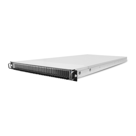
Tailored for hyper scale datacenter and software defined storage, Quanta’s innovative
D51PH-1ULH features a hybrid architecture and an ultra-dense hot-swappable 1U plat-
form. D51PH-1ULH is a rackmount server based on Intel® Xeon® processor E5-2600 v3
product family and features up to 1TB memory capacity. It is equipped with 12x hot-swap-
pable 3.5” disk drives and 4x hot-swappable 2.5” SATA SSD.
Ultra Dense 1U High Computing Storage Server
D51PH-1ULH designs 12 hot-swappable 3.5” disk drives in 1U chassis, and also delivers the
outstanding computing performance with Intel® Xeon® processor E5-2600 v3 product
family. It provides both the extreme density and computing to hyper scale cloud data cen-
ters those require not only the large capacity but also the enterprise class compute capa-
bility. It also helps the IT managers can optimize the rack density and save the overall rack
and data center space. With sophisticated hot-swappable mechanism design, D51PH-
1ULH still provides high serviceability for IT people can do the disk drive maintenance
without stopping the business and operation.
Bring You the Most Efficiency with Onboard Design
This system not only lowers the cost, but also highly increases the efficiency because of its
built-on-board design. All key functions are built on the motherboard, including two 1GbE
RJ45 ports for accessing or managing the server from multiple networks, one dedicated
RJ45 management port, optional 10G Base-T port for high speed data access, and
onboard SATA ports plus LSI 2208/3108 SAS controller for various storage devices. The
exceptional design makes all components work smoothly together. Plus two redundant
700W power supply modules, the system can be ranked as one of the most efficient server
ever.
Sophisticated Hybrid Architecture
Cache is becoming a mandatory requirement in not only software defined storage but
also virtualization application to boost the performance and IOPs. D51PH-1ULH is
equipped with 4x SSD in addition to 12x 3.5” large capacity disk drives, such hybrid archi-
tecture is ideal for tier storage planning which solid-state drive is required to accelerate
IOPs and throughput, in the meanwhile not to sacrifice the large data storage capacity.
Hot-swappable and Easy Service
D51PH-1ULH is designed with delicate architecture to support 12 hot-swappable 3.5”
hard drives within 1U chassis, which provides optimized rack density and also deliver non-
disruptive on-site service. With the design, there is no external cable management arm is
required which is significantly reduce the system deployment and rack assembly time, and
also simplify the rack cable routing in the rear side.

ABOUT YOUR SYSTEM INTRODUCTION
1-2
Specifications
Table 1.1: System Specifications
SPECIFICATIONS DESCRIPTION
Form factor 1U rack mount
Dimensions (W x H x D) 17.6 x 1.7 x 35.0 inches
448.2 x 43.2 x 890.1 mm
Processor
Processor type:
Intel® Xeon® processor E5-2600 v3 product family
Max. TDP support: 135W
Number of processors: 2
Internal Interconnect: 6.4 / 8.0 / 9.6 GT/s
L3 cache: Up to 45 MB
Chipset Intel® C610
Memory
Total slots: 16
Capacity: up to 512 GB RDIMM / up to 1024 GB LRDIMM
Memory type: 2133 MHz DDR4 RDIMM/LRDIMM
Memory size: 32 GB, 16 GB, 8 GB RDIMM / 64 GB, 32 GB LRDIMM
Storage controller
Onboard (Intel® C610):
10x SATA 6Gb/s ports
SATA RAID 0, 1, 10
Optional controller:
Quanta LSI® 2208 6Gb/s SAS mezzanine
Quanta LSI® 3108 12Gb/s SAS mezzanine
Networking
LOM:
One Intel® I350 dual-port 1 GbE
Dedicated 10/100/1000 management port
Optional NIC:
Quanta Intel® 82599 dual-port 10G OCP mezzanine
Expansion slot One x16 PCIe G3 slot
Storage 12 x 3.5" or 2.5" fixed SATA/SAS HDD/SSD
Video Integrated AST2400 with 8MB DDR3 video memory (optional)
Front I/O LEDs: LAN/Power/HDD array/Status/ID
Buttons: ID/Power
Rear I/O
2x USB 3.0 ports
1x VGA port
1x RS232 serial port
2x GbE RJ45 ports
1x 10/100/1000 RJ45 management port
TPM Yes (option)

ABOUT YOUR SYSTEM INTRODUCTION
1-3
Power supply
1+1 High efficiency redundant hot-plug 700W PSU (default with one PSU
only);
100-240Vac, 50-60Hz, 10-5A;
100-240Vac, 50-60Hz, 10-5A or 240Vdc, 3.5A (for China only);
Detailed PSU options please refer to “ordering info” or “CCL”
Rating (per PSU inlet) 100-240Vac, 10-5A, 50/60Hz
Fan 6x systems fans
System management IPMI v2.0 Compliant, on board "KVM over IP" support
Operating environment
Operating temperature: 10°C to 40°C (50°F to 104°F)
Non-operating temperature: -40°C to 70°C (-40°F to 158°F)
Operating relative humidity: 50% to 90%RH
Non-operating relative humidity: 20% to 95%RH
Table 1.1: System Specifications (Continued)
SPECIFICATIONS DESCRIPTION

ABOUT YOUR SYSTEM PACKAGE CONTENTS
1-4
1.2 Package Contents
(1) the system
(1) processor heat sink
(1) power supply unit
(1) power cord (optional)
(1) utility CD (This Guide included)
(1) rail kit
Note:
Note: For exact shipping contents, contact your Quanta sales representative.

ABOUT THE SYSTEM A TOUR OF THE SYSTEM
1-5
1.3 A Tour of the System
System Overview
Figure 1-1. System Component Overview
1
2
3
8
4
5
6
9
7
10
11
12
13

ABOUT THE SYSTEM SYSTEM OVERVIEW
1-6
Table 1.2: Component Overview
NO.ITEM DESCRIPTION
1Storagedrivebay Support storage drive: 3.5” / 2.5” ; SAS / SATA; hard disk drive (HDD) /
solid state drive (SSD)
2 Storage drive board Connect to storage drive
3Fans (x6)Fanmodules
4 Mainboard Provide all the basic function and information for system operation
5 OCP mezzanine slot Supports OCP LAN mezzanine
6 BBU Backup battery unit supports Quanta LSI 2208 SAS mezzanine
7 Quanta mezzanine slot Supports Quanta LAN / SAS mezzanine only
8PowerSupplyUnit Redundant Power Supply Unit (PSU). 700W high efficiency redundant
PSU, 240Vac
9 PDB + SEB Power Distribution Board and SAS Expander Board
10 HDD array 3 This array is composed of HDD0, HDD1, HDD2, HDD3
11 HDD array 2 This array is composed of HDD4, HDD5, HDD6, HDD7
12 HDD array 1 This array is composed of HDD8, HDD9, HDD10, HDD11
13 Release lever and handle Pull the tray release lever up on the tray. Hold the tray handle and pull
the tray out of the chassis smoothly until fully extend

ABOUT THE SYSTEM SYSTEM OVERVIEW
1-7
System Front View
Figure 1-2. System Front View
Front Control Panel
Figure 1-3. Front Control Panel View
Table 1.3: Front Control Panel View
NO.NAME DESCRIPTION
1 Control Panel Control system and status display.
2 Release lever Pull up to release the HDD tray.
3HDD tray handle Hold to pull out the HDD tray from the chassis or push the HDD tray
into the chassis.
Table 1.4: Front Control Panel View
NO.NAME DESCRIPTION
1 Power Button with LED
Power Button:
Push button to power the system on /off. Press more than 4 sec. to
shut down the system.
Power LED (Blue):
On, S0 system power on
Off, S4/S5 system power off
Blinking, S1 Standby/Sleep
2 ID Button Press to light up / off the ID LED to identify this system
1
2
3
SSD0 SSD1 SSD2 SSD3
1
2
3
12
34 67 8
5

ABOUT THE SYSTEM SYSTEM OVERVIEW
1-8
3 ID LED (Blue) On, selected unit ID
Off, no ID requested
4 USB 2.0 port Connects to USB device
5 Status LED (Amber)
Off, Normal
On, DC off and critical error
Blinking, DC on and critical error.
6LAN1LED(Blue) On, link
Blinking, LAN access
7LAN2LED(Blue) On, link
Blinking, LAN access
8 HDD Array # LED (Amber)
Off, HDD row # normal
On, HDD row # fault
Blinking, Predictive Failure Analysis (PFA) error occurs on HDD row #
Table 1.4: Front Control Panel View (Continued)
This manual suits for next models
1
Table of contents
Popular Network Storage Server manuals by other brands

D-Link
D-Link DSN-6020 user manual

American Megatrends
American Megatrends StorTrends 1300i Specifications

Hawking
Hawking Net-Stor HNAS1 user manual

HP
HP 201723-B21 - HP StorageWorks Modular SAN Array 1000 Hard... reference guide

NETGEAR
NETGEAR RNDX400E - ReadyNAS NVX Pioneer Edition NAS... installation guide

HP
HP ProLiant DL38 installation instructions

Seagate
Seagate Business Storage 1-Bay NAS datasheet

Intel
Intel SS4000-E - Entry Storage System NAS Server user guide

Freecom
Freecom SILVER STORE 2-DRIVE NAS Features

Tandberg Data
Tandberg Data StorageLoader Installation and user manual

Dell
Dell XC720xd owner's manual

Iomega
Iomega StorCenter ix4-200d Specifications