Qdis LVTX-1CH Safety guide

Your best partner for better driving

Warning
When installing the main unit, do not remove or alter existing
vehicle fasteners, including nuts, bolts, screw, clips, and fittings.
Never detach, move or alter existing vehicle wiring, including
electrical grounds and straps. Alteration of existing vehicle
components may make vehicle unsafe to operate. Should be
no any electronic devices or magnetic pole around installation
place.
Air bags are vital part of a safety system. Never install main unit
in a way which will alter air bag wiring or interfere with air bag
deployment. Air bags must function properly in the event of an
accident.
Before installing, check the location of pipe, tank, electrical
cables and others.
Read and follow the instruction manual.
Wiring location must not interfere driving, get in or out from car.
Use electrical tape to insulate the ends of all wires, even if they
are not used. Proper insulation prevents arcs, shocks and fires.
When installation is complete, test all vehicle electrical systems
to ensure they operate correctly, including lights, horn, brake
lights, and emergency flashers.
According to our sales policy, any problems caused by user’s
mistake, careless can not be guaranteed.
Caution
All steps of installation should be done by well-trained specialist.
During installation ignition key should be taken off and after all
installation finish connect power cable with interface for the last
step.
Do not install the main unit in places where it ma be exposed to
dew condensation (around the air conditioning hose, etc), or in
locations where it may come in contact with water, high levels of
moisture, dust or oily smoke
Install wiring in a manner in which cables will not come in contact
with metal parts. The wiring may be damaged by contact with
metal parts, resulting in fire and shocks. Avoid all contact with hot
surfaces when wiring the main unit. High temperatures may
damage wiring, causing shorts, arcing and fires.
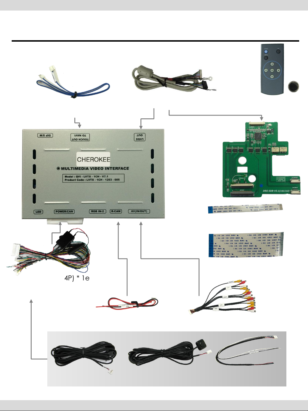
Kindly check all parts are in the box, when receiving the product, if
anything missing, inform to the supplier or manufacturer.
Warning / Caution
2

Contents
1. Specifications
1.1 Main Specifications
1.2 Features
1.3 System Diagram
1.4 Components
1.5 Exterior
2. Installation
2.1 Installation Diagram
2.2 Use caution
2.3 Installation
3. Settings
3.1 DIP switch
3.2 Remote control
3.3 OSD (On Screen Display)
3.4 Factory Mode
3.5 Rear Parking Guidelines
3.6 Touch Calibration
3.7 Remote button Input
3.8 DVD, DTV model
3.9 Mode switch by CAN wire
4. Trouble Shooting
1
2
3
4
5
6
7
8
9
10
11
13
14
15
16
18
19
20

1. Specifications
-1-
1. Compatible Vehicle
Jeep Grand Cherokee 2014, Dodge Durango 2014
1. Main components
Multimedia Interface * 1EA
Sub-board * 1EA
2. MULTIMEDIA INTERFACE input specification
3 * A/V (NTST&PAL) input
1 * CVBS(Rear camera) input
1 * Analog RGB
1 * LCD input (Car system input)
3. MULTIMEDIA INTERFACE output specification
1 * LCD output(LCD performance)
1 * Audio output
2 * CVBS output
4. Power Spec
- Input Power : 8VDC ~ 18VDC
- Consumption Power : 4WATT, Max
5. Switch Input mode
-AV mode skip : Able to skip or display AV mode by controlling
DIP Switch
-Able to switch the input mode with the remote control
-Possible to switch Input mode with switch for source toggle
-Possible to switch mode through OEM button on the steering
wheel due to CAN connection
1.1 Main Specification

1. Specifications
-2-
Able to adjust DVD, NAVI display on screen
Improved Screen Display (user-oriented interface)
Add SAFE function (Displaying the main page while driving)
1.2 Features

1. Specification
-3-
1.3 System Diagram
DISPLAY
A/V 1
NAVIGATION Input
(Analog RGB)
CVBS
(Rear camera)
Car Screen Input
(CAR MAIN BOARD)
A/V 2
A/V 3
VIDEO
CIRCUIT
VIDEO MUX
MCU
Power Input
(+8VDC ~ +16VDC)
POWER
CIRCUIT
Dip S/W
A/V OUT HEADREST
MONITOR
Remote control Switch for source toggle
OEM Navi Button (Can Signal)
Car Installation
OEM LCD

1. Specification
-4-
1.4 Components
POWER cable (24P) * 1ea
(HPOWER0011)
LVDS cable * 1ea
SUB BOARD* 1ea
(QCPASS0581)
+ LABEL
(LABELS0160)
REMOTE CONTROL * 1ea
(REMOTE0001)
(HLVDSC0020)
A/V cable * 1ea
(HAVCAB0002)
TOUCH OUT cable * 1ea
(HTOUCH0004)
REAR CAMERA POWER cable * 1ea
(HARETC0002)
IR cable * 1ea MODE cable * 1ea RGB cable * 1ea
(HARETC0001) (HNAVIC0004)
(HIRCAB0002)
8P FFC Cable * 1ea
(FFCABL0018)
60P FFC Cable * 1ea
(FFCABL0012)

1. Specifications
-5-
1.5 Exterior
Dimension
Width 125mm
Length 105mm
Height 21mm
- SUB BOARD -
⑫
⑨
⑪
⑩
⑨LVDS-IN
⑩COMAND IN
⑪LCD OUT
⑫T/S OUTPUT
⑬T/S INPUT
⑬
①LED
②POWER
③RGB IN-2
④R-CAM
⑤AV(IN/OUT)
⑥DIP Switch
⑦TOUCH OUT TO NAVI
⑧LVDS OUT
⑥⑦⑧
①②③④⑤

2. Installation
-6-
2.1 Installation Diagram
IR-AV2 (DVD)
AUX-ON (N.C)
CAN-L
CAN-H
IR-AV3 (DTV)
IR-AV1 (NAVI)
PARKING (SAFE)
REAR
OPT2 (N.C)
MODE : Toggle S/W
IR
PB12 (N.C)
GPIO-ZO : MMI
GND
ACC
RGB
REAR (9V OUT)
GND
AV1
AV2
AV3
REAR C
Audio L
Audio R
AV/OUT Video
Navigation Touch cable

2. Installation
-8-
2.3 Installation
The back side of
OE monitor looking is like
this picture .
Please remove the back cover .
Please remove OE board inside
and please disconnect
the OE steel plate.

2. Installation
-8-
2.3 Installation
Please find out OE FPC cable
and OE touch cable.
OE FPC Cable
OE Touch cable
①Please disconnect the cables.
After that, please remove
OE board .

2. Installation
-8-
2.3 Installation
①Please mount provided sub-board as like the below picture
(please use a kind of double tape.) And please connect OE FPC cable
to “LCD-OUT”connector and OE touch cable to “T/S INPUT connector.
②Please connect provided 60P FFC cable to “COMMAND IN” and
8P FFC cable to “T/S OUTPUT” connector.

2. Installation
-8-
2.3 Installation
①Please re-mount OE board and please connect provided FFC cables
to OE board. (Please refer to below picture.)
After that, please connect LVDS cable to cub-board of “LVDS-IN” connector.

2. Installation
-8-
2.4 CAN connection
As shown above, connect the provided CAN-H wire(green+brown) to original
CAN-H wire(white+blue) and connect provided CAN-L wire(green) to
original CAN-L wire(white+yellow)
CAN-Low
CAN-High
Power cable
Find OEM LCD cable back of the monitor

3. Installation
-9-
3.1 DIP Switch
PIN
Function
Dip S/W choice
1
RGB input skip ON : RGB mode skip
OFF : RGB display
2
A/V 1 skip ON : A/V 1 skip
OFF : A/V1 display
3
A/V 2 skip ON : A/V 2 skip
OFF : A/V2 display
4
A/V 3 skip ON : A/V 3 skip
OFF : A/V3 display
5
No USE
6
No USE
7
Rear Camera ON : External(A/S) rear camera
OFF : OEM rear camera
8
No USE
※ ON : DOWN / OFF : UP
※ For example :DIP S/W
- input mode: in case of using
AV3, Navi(RGB
- No use for OEM navigation
- Rear Camera : in case of
connecting toCVBS4
▷DIP S/W : 1 OFF
▷DIP S/W : 2,3 ON (input mode skip)
▷DIP S/W : 4 OFF (A/V3 possible)
▷DIP S/W : 5 ON
▷DIP S/W : 6 ON
▷DIP S/W : 7 ON (CVBS4 possible)
▷DIP S/W : 8 OFF
※ After changing the settings for DIP switch, reboot the power by
disconnecting the power cable.

-19-
3. Settings
3.2 Remote Control
Key
Function
POWER Unavailable
PIP A/V 1~2 Mode : Remote control UI Display
A/V 3 Mode : Mode switching UI Display
MENU Activating OSD menu
OK Making a selection, changing image display
▲Moving upward
▼Moving downward
◀
Moving leftward
(If you press this button 2 seconds long, you can access the factory
mode.)
▶
Moving rightward
(If you press this button 2 seconds long, you can reset all the
data about user environment.)

3. Setting
-11-
3.3 OSD (On Screen Display) / Analog RGB Mode
OSD
* LANGUAGE : To change the
language displaying on touch
OSD (Chinese, English only)
* TRANS : Transparency
control of the OSD
* H_POSITION
: Horizontal movement
of the OSD window
* V_POSITION
: Vertical movement
of the OSD window
IMAGE
* BRIGHTNESS
* CONTRAST
* SHARPNESS
* USER IMAGE
: To choose the option
among 4 prepared color
shade.
COLOR
* RED : Adjusting red
* GREEN : Adjusting green
* BLUE : Adjusting blue
* USER COLOR
: To choose the option by user
UTIL
* FACTORY RESET
-To reset all the values about
navigation, DVD screen to
factory default. (NOT
available for reset of the
position value of images, only
for functions inside OSD menu)

3. 설정
-12-
3.3 OSD (On Screen Display) / Video Mode
IMAGE
* BRIGHTNESS
* CONTRAST
* SATURATION
* HUE
* SHARPNESS
* USER IMAGE
: To choose the option
among 4 prepared color
OSD
* LANGUAGE : To change the
language displaying on touch
OSD (Chinese, English only)
* TRANS : Transparency
control of the OSD
* H_POSITION
: Horizontal movement
of the OSD window
* V_POSITION
: Vertical movement
of the OSD window
UTIL
* FACTORY RESET
-To reset all the values
about navigation, DVD
screen to factory default.
(NOT available for reset of
the position value of images,
only for functions inside OSD
menu)
)

3. Setting
-13-
3.4 Factory Mode
UTIL
* CALIBRATION : Touch calibration
•IR MEMORY : To register value of buttons on
the remote controller
•DVD TYPE : Setup for the type of DVD
•DTV TYPE : Setup for the type of DTV
* JOG SUTTLE : Setup for use of JOG SUTTLE
DVD, DTV control
OSDmenu ON/OFF setting
* FACTORY RESET : reset
PARK
* PARK ENABLE : Setup of rear view
parking guide line
•PARK SETUP : Control over position
of rear view parking guide line
* SAFE ENABLE : To select whether to
use SAFE function (NOT to allow
watch video while driving) or not
IMAGE
* H-POSITION : Control over
horizontal movement of screen
* V-POSITION : Control over vertical
movement of the screen
* NAVI MODEL : DEFAULT,
KD900(WVGA), MD7000(WVGA),
MYVI(WVGA),PAPAGO(WVGA)
GN3000(WVGA), ICUBE(WVGA)
MYVI(WVGA), I-ONN(WVGA)
* AVOUT SELECT : DEFAULT, AV1,
AV2, AV3
FACTORY mode –Factory mode: press ◀button 5 seconds long

3. Setting
-14-
3.5 Parking guide line setting
PARK
* PARK ENABLE : Selecting whether to
display the parking guide line or not
on rear gear (default : OFF)
* PARK SETUP : Adjusting the position of
the parking guide line (available in
PARK SETUP -> V-POSITION, H-POSITION)
* SAFE ENABLE : In case of Connecting
“Safe” wire from the power cable to
the hand break,
ENABLE –OEM Picture displays in Drive
gear position
DISABLE –No display locked in any
gear position
PARK - ENABLE
A. If you set ‘PARK ENABLE’ as
“ON” state, there will be the rear
view parking guide line.
(as shown above picture)
B. Press the OK button of remote
control, ‘’H_POS’’ will be shown
on the right and control moving
in horizontal direction.
PARK - ENABLE
A. Press the OK button of remote
control one more, ‘’V_POS’’ will
be shown on the right and control
moving in vertical direction.
※In case of installing rear
camera : Put DIP S/W 7 down
to set “ON”(Page 9)
FACTORY mode –Press ◀button 5 seconds long on the remote control
Table of contents