QSI 520 User manual

500 Series User Guide
Revision 1.1
March, 2007
Disclaimer:
The specifications in this document are subject to change without notice.
All trademarks mentioned in this document are the property of their respective owners,
and are used herein for informational purposes only.
©2007 Quantum Scientific Imaging
Phone 888-QSI-4CCD • www.QSImaging.com

ii
Table of Contents
1. GETTING STARTED
What’s In the Box? 2
Get to Know Your Camera 3
Install Software and Drivers 4
Confirm Installation and Camera Operation 4
Launch MaxIm LE 4
Connect the camera 5
Take an image 7
View the image 8
2. CAMERA FEATURES
AND OPERATION
Camera Attachment Options 9
Using SLR Lenses 10
Attach the camera to your telescope 10
Electrical Connections 11
DC Power Connector 11
USB Connector 12
Guider Control Port 12
Cooling the Camera 14
Standard Air Cooling 14
Liquid-Assisted Cooling 14
How Much Cooling Is Enough 15
Controlling the Cooler 16
Internal Color Filter Wheel 18
Advanced Setup Options 19
Camera Selection 20
Status Indicators 21
Imaging Options 21
Status and Notification 23
Camera Status Indication 23
Camera Error Indication 23
Audible Beeper 25
Imaging Application Messages 25
3. CCD IMAGING OVERVIEW
How CCDs work 26
Types of CCDs 26
Full-Frame CCDs 26
Interline transfer CCDs 27
Anti-Blooming CCDs 27
Microlenses 28
Single-shot color CCDs 28
Signal versus noise 29
Reducing noise in CCD images 30
Dark Frames 30
Flat Fields 32
Bias Frames 34
Stacking Images 35
Color images 36

4. TAKING IMAGES
Launch MaxIm LE 37
Camera Control Window 38
Cool the CCD 40
Focusing with MaxIm LE 41
Take a series of images 43
Image Calibration 45
ark Frames 46
Bias Frames 46
46
47
4
47
49
on in MaxIm LE 50
axIm LE 54
s in MaxIm LE 55
58
Using the internal Color Filter Wheel 61
62
Cont 62
5. GUIDING
Autoguider support in MaxIm LE 63
Using an AutoGuider 64
Using a QSI Camera as an AutoGuider 67
6. ACCESSORIES
T-mount adapter 69
2” nosepiece 69
1 ¼” nosepiece 69
C-mount adapter 69
LR lens adapter 70
iquid heat exchanger 70
70
70
ox 70
ENANCE
71
oving color filters 71
72
Cleaning the CCD cover glass 72
echnical support 73
ES
Series Specifications 74
77
Take a single image 42
View the image in MaxIm LE 43
D
Flat Fields
Flat Darks
Manual Image Calibration 7
Subtract Dark Frames
Scale by Flat Fields
Automatic Calibrati
Calibrate Images in M
Combine Frame
Binning
Shutting down your camera
rolling with other software
S
L
Recirculating pump
Color filter wheel
Guider Breakout B
7. CARE & MAINT
Cleaning the exterior
Installing or rem
Cleaning the color filters
Recharging the desiccant 72
T
APPENDIC
Appendix A – 500
Appendix B – Warranty

QSI 500 SERIES USER GUIDE
1
Getting tStar ed
Thank you for your purchase of a QSI 500 Series Camera.
The QSI 500 Series family of t ermoel meras is designed
produce scientific-grade imag with wid ent linearity and l noise.
Your QSI 500 Series camera w ll provi properly treated and
o get the most fr your mend that you read this ser
ghly and follow the included
in a hurry to try out your new camera and are familiar with the general operation of
ed” section provides the basi
take yo r first i nd the
ed with MaxI LE fo .
h
es
ectrically cooled CCD ca to
e dynamic range, excell ow
i de years of service if
maintained. T om camera, we recom U
Guide thorou precautions.
If you’re
CCD cameras, this “Getting Start
setup your camera and u
c information you will need to
mage. Please refer to the full User Guide a
online help provid m r complete instructions
The QSI 500 Series Camera Family Showing Different Body Styles
Sectio
n
1

QSI 500 SERIES USER GUIDE
2
What’s In the Box?
Your QSI 500 Series camera was shipped in a water-tight Pelican case
foam to provide the ultimate in protection. Please take a few minutes to
camera to make sure that it has arrived in good condition, and that the c
items listed below. Note that additional items purchased at the time of o
included as well.
Camera body
epending on configuration
-Mount depending on configuration
Body cap T-Mount or C-Mount depending on configuration
(100-240VAC, 50-60Hz) with
detachable, region-specific AC power cord
ing:
py of MaxIm LE
with custom-cut
examine your
ase contains the
rder may be
Nosepiece 2” or 1 ¼” d
Mounting Adapter T-Mount or C
AC Power Adapter Universal AC power supply
USB Cable 10 ft. USB 2.0 cable
Guider Cable 14 ft. guider cable with modular connectors on each end
Tools Tool kit for camera maintenance
Documentation envelope containing the follow
Quick Start Guide
CD-ROM containing the Installation program, MaxIm LE, the USB and
camera drivers, and the Installation Guide and this User Guide in PDF format.
A document with the serial number for licensing your co
Open Pelican case showing QSI 500 Series camera and standard accessories

QSI 500 SERIES USER GUIDE
3
Get to Know Your Camera
and features of your camera.
Take a few minutes to familiarize yourself with the external
connections
The image above shows the major external features of a typical QSI 500 Series camera.
The depth of the Camera Cover on your camera may differ depending on the internal
options installed.

QSI 500 SERIES USER GUIDE
4
Install Software and Drivers
The USB drivers and associated software included on the installation CD-ROM must be
installed before connecting your QSI camera to your computer.
Note: cted to do so
during
Refer to the QSI 500 Series Camera Installation Guide for complete software and
tallation instructions.
m Installation and Camera Operation
cessful installation of the camera and the associated software is complete, you
n quickly test your camera with MaxIm LE if you choose. Leave the camera USB cable
and power supply connected, and follow the steps below.
Launch MaxIm LE
After installing the camera drivers and MaxIm LE from the Installation CD-ROM, launch
MaxIm LE by double-clicking the MaxIm LE icon on your desktop or by selecting
“Programs > MaxIm LE > MaxIm LE” from the Windows Start menu.
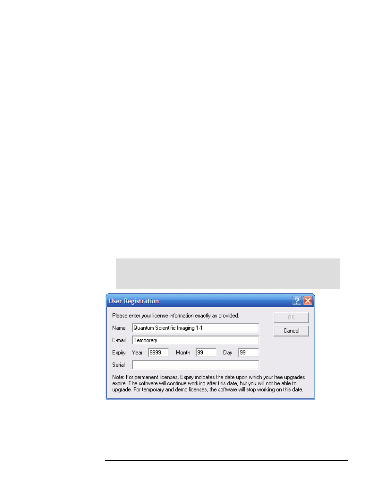
The first time you run MaxIm LE you will be asked to enter your temporary User
Registration information. Enter the Name, Email, Expiry dates and Serial number
information exactly as printed on the MaxIm LE License Information sheet included in the
documentation envelope with your camera.
Do not connect your camera to your computer until instru
the camera installation process.
hardware ins
Confir
After the suc
ca
Caution: Do not enter your real name and email address. Enter the information
exactly as printed on the included MaxIm LE License Information sheet.
This license will work for 30 days.from the time it is installed. You must register direc
with Diffraction L
tly
imited to receive your permanent license. Select Register Online
from the Help Menu in MaxIm LE and follow the given directions to receive your permanent
license.

QSI 500 SERIES USER GUIDE
5
Connect the camera
Select “Camera Control Window” from the View menu to open the Camera Control
Window.
MaxIm will open the Camera Control window and display the Setup tab. After MaxIm is
installed it must be told which camera to use.
Click the “Setup” button in the upper left corner under Main CCD Camera.

QSI 500 SERIES USER GUIDE
6
Select “QSI Universal” from the Camera Model list box. Click OK.
That will take you back to the Camera Control Window. If you have a QSI camera with an
internal color filter wheel you’ll also need to tell MaxIm about that by clicking “Setup” under
“Filter Wheel” toward the upper right of the Setup tab.
Select “QSI Universal” as the filter wheel model. Click OK.

QSI 500 SERIES USER GUIDE
7
Click the “Connect” button to establish communication between MaxIm and your QSI
camera. If MaxIm fails to connect to the camera, double-check that power is supplied to the
camera and that the USB cable is securely connected. Once MaxIm connects to the
camera the Camera Control window will look like this:
Note: This example assumes the camera does not have a color filter wheel. If
you setup a filter wheel, “QSI Universal” will be displayed under Filter Wheel in
the dialog above.
Take an image
Click the “Expose” tab along the top of the Camera Control window.
There are several fields and buttons in this window. On the left is a series of radio buttons
to select the type of frame to expose. The options are Light, Bias, Dark and Flat. Click the
button next to “Bias” to select a bias frame. A bias frame is an exposure with the shutter
closed of essentially zero exposure time. The Minutes and Seconds will be grayed
indicating that the exposure time can’t be modified for a bias frame. Make sure the Delay is
set to “0”. Click “Expose” to take one bias frame.

QSI 500 SERIES USER GUIDE
8
View the image
MaxIm will instruct the camera to acquire a bias frame and then automatically download
and display the resulting image. Your screen should look something like this.
Your display may vary somewhat from the screen shot above and the image displayed may
be larger or smaller than that shown depending on your camera model. While a room
temperature Bias image isn't very exciting, this does provide confirmation that your software
and camera are installed and working properly.
Congratulations, you have just connected your new QSI 500 Series camera and
acquired your first image. If you’re familiar with MaxIm LE or MaxIm DL, or
are using some other camera control software such as CCDSoft from Software
Bisque, you are now ready to begin taking additional images.
For all users, but especially if you’re new to CCD imaging with MaxIm LE, we
suggest you read the entire QSI 500 Series Camera User Guide to familiarize
yourself with all of the features and capabilities of your new QSI camera.

QSI 500 SERIES USER GUIDE
9
Camera Features and Operation
Camera Attachment Options
The camera can be attached to your telescope or lens in a variety of ways. The image
bove shows the industry standard T-Adapter with an attached 2" nosepiece. An optional
nosepiece is also available. The T-Adapter is compatible with a wide variety of
standard accessories.
An opti r and
is com ent
such a
a
1.25"
onal C-Adapter adapter is also available. The C-Adapter replaces the T-Adapte
patible with many standard lenses, lens mounting accessories and other equipm
s microscopes.
Note: The T-Adapter has industry standard 42mm diameter x 0.75mm pitch
threads. The C-Adapter has industry standard 1" x 32TPI threads. Always make
certain that any device you attempt to thread into either adapter has proper
matching threads. Some optical components have threads that look like they
might work, but have slightly different dimensions. Never force-thread
anything into the adapters.
Sectio
n
2

QSI 500 SERIES USER GUIDE
10
Using SLR Lenses
The C-Adapter can be used to attach many standard
SLR lens attached to your camera. The image at the
right shows an Olympus OM series SLR lens
attached to a QSI Model 520i camera. Optional SLR
lens adapters are available to fit a variety of popular
SLR camera lenses. See Section 6 in this Guide for a
list of available adapters and compatibility
requirements.
Note: Custom mounting adapters can be employed to satisfy many unique or
non-standard mounting requirements. Contact QSI for the dimensions and
requirements for custom mounting adapters.
Attach the camera to your telescope
The picture below shows a QSI 500 Series camera with 2" nosepiece being fitted to the 2"
focusing tube of a refracting telescope. Always use the largest nosepiece that your
telescope will allow to minimize any vignetting of your image.
e correct diameter nosepiece firmly screwed in to the front of the camera, carefu
he nosepiece into the eyepiece adapter on your telescope. Tighten any retaining
or screws to ensure the camera i
With th lly
guide t
screw s stable and will not slip or move when the
orientation of the telescope changes.

QSI 500 SERIES USER GUIDE
11
Electrical Connections
camera body to
rotect the connectors when no
cables are attached.
DC Po
The camera is ordinarily powered by the included AC power adapter which plugs into the
le connector on the bottom of the camera. The AC power adapter accepts any input
voltage from 90v to 240v and 50-60 Hz. It is supplied with a region-specific AC power cord.
cator on the back of the
camera will
nected via the USB cable.
The Camera Status Indicator will glow solid green once the camera is connected to the
computer via the USB cable. See the Status and Notification discussion later in this
Section for additional detail.
The image at the left is a close-
up of the bottom of the camera
body. All electrical connections to
the camera are made through the
three connectors located on this
connector panel. The panel is
recessed into the
p
wer Connector
midd
Shortly after power is applied to the camera, the Camera Status Indi
camera will start glowing yellow indicating that the camera is starting up. The
make a small “chirp” sound and then a few seconds later will make a “chirp chirp” sound
indicating that the camera successfully completed its initialization steps. The Camera
Status Indicator will begin flashing green if the camera is not con
Note: Power-up initialization can take up to 6 seconds. It is not possible to
connect to the camera from the imaging application (MaxIm LE, CCDSoft, etc.)
during this time. Any attempt to do so will cause an error message to be
displayed by your imaging application.
Note: The camera is designed to operate on stable, clean 12v DC power and
consumes less than 2 amps at full power. Voltage below 11v and above 15v can
increase power dissipation or lower cooling efficiency. If the voltage is outside
of this range the camera will 'notify' the user every 4 seconds until the voltage is
back within range. See Status and Notification below.
The camera power connecter uses a standard 2.1mm coaxial connector with
center positive.

QSI 500 SERIES USER GUIDE
12
Caution: Because of the wide range of potential power sources (especially with
field operations that can also employ batteries, generators, DC inverters, etc.)
there is the real possibility of damaging your camera and other electrical
equipment by creating unexpected ground loops and different ground reference
potentials between your equipment.
It is highly recommended that the included AC adapter be used to power the
camera at all times. If a power source other than the included AC adapter is used,
it is your responsibly to insure that it is suitable. Avoid sharing the camera DC
power source with other devices that can produce excessive noise (old technology
dew heaters, etc.) and possible ground loops that could interfere with the reliable
operation, or even damage your imaging equipment.
If you choose to use a power source other than the included AC adapter and are
uncertain about meeting these requirements, please contact QSI for assistance.
USB Connector
The camera's USB interface is compatible with USB 2.0 and 1.1. The included USB 2.0
cable plugs into the USB port on the left side of the camera connector panel. The other
side connects to any standard USB port on your computer. All camera control commands
and resulting images are passed over the USB cable.
Note: Do not connect your camera to your computer unless you have successfully
installed the camera software and drivers.
After the camera power-up initialization is complete, and the camera's USB cable is
connected to your computer,
the computer will make a Plug-N-Play sound indicating that a
ce was connected to the computer. This means that your camera is ready and is
listening for commands to be sent over the USB connection.
devi
Note: QSI 500 Series cameras do not draw power from the USB bus. Powered
hubs are not necessary for operation.
Guider Control Port
All QSI with
MaxIm
duratio ed as
the 'Gu
The Gui eme
is com
conduc pe cable is required for connecting the camera to the mount's guider
input. This type of cable is commonly available at retailers such as Radio Shack. A 14 ft.
n of this cable is supplied with 500 Series cameras.
500 Series cameras have a Guider Control Port that can be used in conjunction
LE (or other CCD imaging software) to 'guide' your telescope mount for long-
n astro-imaging. Ordinarily, the Port is only operational if the camera is being us
ider' camera.
der Port employs an RJ-25, 6-conductor modular connector. The interface sch
patible with most modern telescope mounts. Typically, a 6P6C (6 position, 6
tor) telephone-ty
versio

QSI 500 SERIES USER GUIDE
13
The image below summarizes how the Guider Port and compatible cable are wired:
Note: The Guider Port outputs employ optically isolated solid-state switches that
mimic the traditional behavior of older technology mechanical relays. The optical
isolation prevents potentially interfering or damaging ground loops between the
camera and mount.
This newer approach is compatible with most modern telescope mounts (Meade,
Losmandy, Software Bisque, etc.) that employ logic inputs pulled to VCC with a
suitable load resistor.
QSI also offers a Guider Break-Out Box with mechanical relays that can be
employed to adapt to virtually any older or non-standard mount configuration.
Caution: Do not apply more than 50v or 50ma to the guider port pins. The
'Common' input must be at ground, or zero volt potential relative to the control
inputs of your mount. Contact QSI if you are uncertain about your mount's
electrical characteristics.

QSI 500 SERIES USER GUIDE
14
Cooling the Camera
oling the CCD is essential for successful astro-imaging. Cooling dramatically reduces the
thermal noise in an image and makes long exposures practical. See the discussion in the
'CCD Imaging Overview' Section on dark current and noise.
QSI 500 Series cameras use a very efficient thermo-electric cooler (TEC) which relies on
the 'Peltier Effect' to cool the CCD. When power is applied to a TEC, one side of the device
gets cold and other side gets hot, essentially pumping heat from the cold side to the hot
side. All QSI 500 Series cameras employ a two-stage TEC to increase the differential
cooling effect.
The more power applied to the TEC, the grea
can get. The heat pumped from the CCD, as well as the power dissipated by the C,
es a significant amount of excess heat that must be removed from the camera. QSI
500 Se
Stand
The ba
directly automatically controlled cooling fans force air through these fins.
The m ved
from th
Keep in temperature that the CCD can be cooled is limited by the
ambien res
is easy
even ne ble
to cool the CCD to the desired temperature. See the specifications for your camera to
rmine the maximum cooling differential you can expect under typical conditions.
Liquid
Forced
needed
Howev rticularly
demanding situations, additional cooling can
be achieved with the optional Liquid Heat
Exchanger, or LHX. The LHX utilizes
recirculating water for more efficient removal
of heat from the camera. All things being
equal, the LHX can provide an additional 7ºC
to 10ºC of CCD cooling. It attaches to the
rear of the camera body as illustrated in the
image to the right. The water flows through
the two hoses, colored blue in this picture.
Self-sealing quick-disconnect couplings are
used to attach the hoses to the LHX so that
the hoses can be removed easily without
leakage of the recirculating water.
There are numerous ways of supplying recirculating water for the camera. One of the
simpler and more common methods for astro-photography is to place a small submersible
pump into a 5 gallon plastic pail full of cool water. The temperature of this amount of water
Co
ter the differential cooling and the colder the
CCD
creat
TE
ries cameras employ two different methods for removing this heat.
ard Air Cooling
ck of a QSI 500 Series camera acts as a large heatsink with cooling fins machined
into the body. Two
ovement of air through the cooling fins greatly increases the amount of heat remo
e camera.
mind that the lowest
t air temperature and the speed of the cooling fans. Achieving very low temperatu
when imaging outdoors during cooler weather. If it is particularly cold you may not
ed to turn the fans on. It the weather is quite warm and humid you might not be a
dete
-Assisted Cooling
air cooling is usually all that is
to reach normal levels of cooling.
er, in warm weather or pa

QSI 500 SERIES USER GUIDE
15
will only rise by a few degrees after a full
Liquid Heat Exchanger, see the Acce
night of imaging. For additional details on the
ssories section below.
Note: The Fans can usually be turned off when using the LHX. In fact, the
fans may actually decrease the cooling ability if the air is warmer than the liquid.
Caution: It is generally advised that only water be used in the LHX. Coolants
such as ethylene glycol and some solvents may damage the seals and gaskets.
How Much Cooling Is Enough
Good results can be obtained with the CCD cooled to -10ºC when taking modest length
exposures. This is easy to achieve with forced air cooling when the ambient air is at 25ºC
lts in nearly a 50-fold decrease in CCD dark current. For more
d by the intrinsic read noise of the CCD itself. The camera will actively
prevent the CCD from being cooled below -40ºC.
(77ºF). Cooling to -10ºC resu
demanding imaging and longer exposures, lower temperatures are desirable. Cooling the
CCD to -20ºC and -30ºC lowers the dark current by a factor of 130 and 400 respectively.
Cooling below -30ºC results in a diminishing improvement as the noise from the dark
current is outweighe
Fahrenheit -40F -20F 0F 20F 32F 40F 60F 80F
Celsius -40C -29C -18C -7C 0C 4C 16C 27C
Note: Refer to the specification sheets at the end of this Guide for the exact
cooling specifications for your particular camera model. Keep in mind that
ambient temperature changes, air movement, and even relative humidity can
affect the temperature that the camera can reach and maintain.
Note: The cooler is not designed to raise the temperature of the CCD above
the temperature of the camera body, i.e. it can not heat the CCD. If the ambient
temperature is -10ºC, the cooler can not bring the CCD temperature up to 0ºC.
When using forced-air cooling the body of
can be up to 12ºC warmer than the
the camera and the window of the CCD chamber
surrounding ambient air temperature. By definition, the
camera will be above the dew point (or frost point) and condensation will not form. When
Dusing the LHX there is the opportunity to drive the enclosure of the camera and the CC
chamber window significantly below ambient temperature if the recirculating water is colder

QSI 500 SERIES USER GUIDE
16
that the surrounding environment. If the relative humidity is high enough, this action cou
drop the camera below the dew/frost point and condensation will fo
ld
rm.
Caution: Do not allow excessive dew or frost to collect in or on the camera.
Exercise the normal precautions that you would with any precision optical or
electronic device. Never use the LHX to drive the camera temperature so low
that liquid water forms on or in the camera. Under certain conditions excessive
moisture can impair or damage the optical coatings and the internal electronics.
the Cooler
om your CCD imaging application (MaxIm,
e.
t
ºC,
Controlling
The operation of the cooler is managed fr
CCDSoft, etc.) When power is first applied to your camera the cooler is in an inactive stat
It must be actively turned on. The following explores the technical details of camera cooling
utilizing MaxIm as the imaging application. For step-by-step operating instructions and
changing the CCD setpoint temperature, see Section 4.
Below is a snapshot of the Setup tab in the Camera Control window, just after the Connec
and then Cooler On button was clicked. Notice that the current CCD temperature is 23
the default Setpoint is 0ºC, and that the cooler power is 100%
en the Cooler On button is clicked, the camera immediately starts cooling the CCD at full
cooler will stay at full power until it has cooled the CCD to within a few degrees
of the s
cooler y
slightly
couple
achieved, the camera will keep the CCD temperature within 0.1ºC of the setpoint.
he following is an image of the same Camera Control window 5 minutes after clicking the
Wh
power. The
etpoint temperature. The camera will then start adjusting the power applied to the
as it approaches the setpoint temperature. The displayed CCD temperature ma
over-shoot the setpoint temperature as the regulation servo locks. It can take a
more minutes for the temperature servo to achieve a solid lock. After lock is
T
Cooler On button. Notice that the CCD temperature is now being regulated at 0ºC and that
the power level has settled down to a modest 40%.

QSI 500 SERIES USER GUIDE
17
Note: Depending on the ambient temperature and Cooler setpoint, the time to
reach the setpoint temperature can take as long as 15 minutes. Once the CCD
temperature has stabilized at the setpoint value, it is recommended to allow the
entire camera an additional 5 to 10 minutes to reach thermal equilibrium.
Note: Best regulation is achieved when the power to the cooler is kept below
85%. This gives the camera some headroom to compensate for variations in the
ambient temperature. If the camera can not reach the desired temperature, it will
keep trying by running the cooler at 100% power indefinitely. If the desired
temperature hasn’t been reached within 15-20 minutes, or the power level is
above 85%, we recommend selecting a higher Setpoint temperature.
Caution: Be careful not to block free air movement around the camera, or any
air flow through the fans and cooling fins on the rear of the camera.
This manual suits for next models
7
Table of contents
Other QSI Security Camera manuals