Quilt EZ King Quilter II User manual

King Quilter II Installation Instructions
1. Tablet Bracket
Remove the two tablet bracket screws as
pictured.
Align Butler tablet bracket as pictured and
replace tablet bracket screws.
Butler tablet should appear as pictured.
**Note: Do not remove this screw.

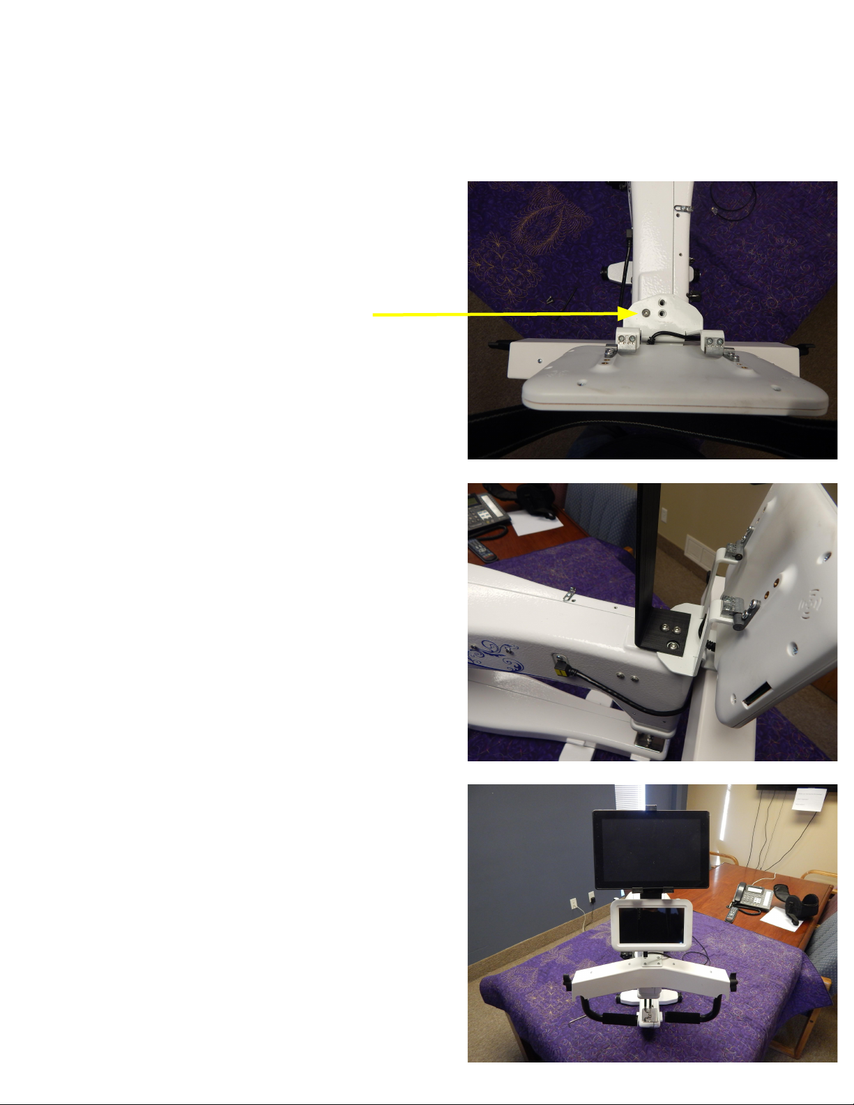
Connect micro USB and DC connectors of the
remote cable to the tablet as pictured. The
opposite end of the remote cable will connect
to the Butler in the remote port.
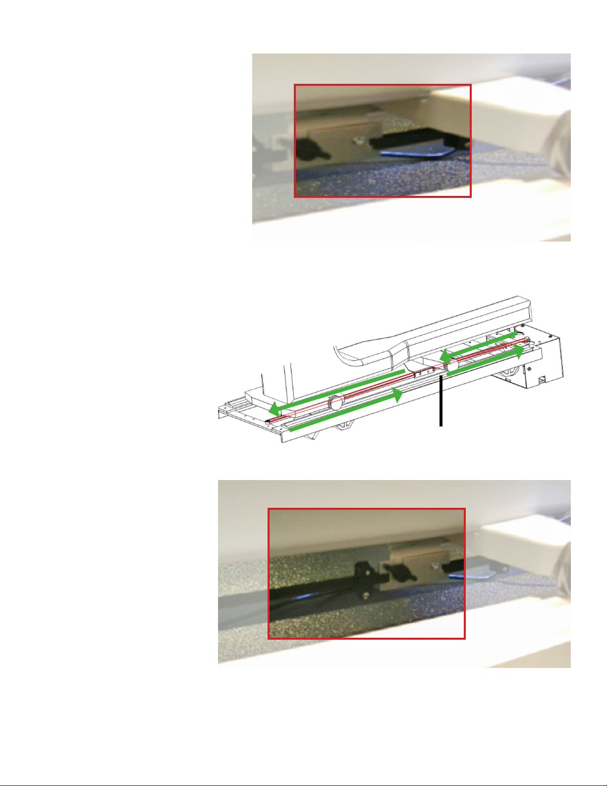
2. Handlebar Cable
Connect the USB connector of the handlebar
cable to the King Quilter II as pictured. The
opposite end of the handlebar cable will
connect to the Butler in the handlebar port.

How to Attach
Butler Robotics to a
Handi Quilter/Baby lock
with Studio, Fusion,
Pearl, or Momentum
Frame
Revision: 6/23/16

Page 2
Bag # Contents Picture
Z3 1 - Motor Pulley Cover
2 - Nuts (M5 K-Lock)
Cables Vary by machine
Z1 5- Plastic Anchors
2- Screw (M5 x 12mm)
2- Washer (M5)
1- Stylus
5-Zip ties
Y1 1 - Black Belt (86”)
4 - Plastic Belt Clamps
4 - Screw (4-40 x 0.5)
X1 1-White belt (12’)
4 - Plastic belt clamps
4 - Screw (4-40 x 0.5)
In order to accommodate all machine types we use universal
parts bags, not all parts will be used in every installation.

Page 3
D5
X7 (Studio Frame)
or
X5 (Pearl/Momentum)
2- X-belt Bracket
2- Eye bolt (M5 x 40mm)
4- Locknut (M5)
Y13 1- Carriage bracket
1- Pan-head screw (#10-24 x
1/4”)
1- umb screw (#10-24 x 1/2”)
2- Pan-head screw (#10-24 x
1/2”)
1- Y-belt bracket
I8 1- Rear idler bracket
1- Tensioner bracket
2- Lock nut (1/4”-20)
2- Machine screw (1/4”-20 x 1”)
1- Pulley assembly
M8 1- Motor box bracket
2- Lock nut (1/4”-20)
2- Screw (1/4”-20 x 1”)
Bag # Contents Picture
1 - Universal Display Bracket
4 - Screw (M6 x 8mm)
4 - Nut (M6)
2 - Screw (8-32 x 0.5)
2 - Poly disc washers
2- Screw (M4 x 20mm)
2- Washer
3- Hex head bolts (M6 x 45mm)

Page 4
Attach the Front Carriage Bracket (Bag M8)
Install the motor box
bracket underneath the
front of the carriage.
Line the holes on
the bracket with the
existing holes on the
carriage.
Fasten in place with
the provided
1/4”-20 x 1” screws
2
Attach the front
carriage bracket to
black motor box
using the provided
M5 x 12mm screws.
1
Front Carriage
Bracket
Black Motor Box

Page 5
Line the idler bracket
with the existing holes
on the rear of the
carriage and attach
it using the provided
1/4”-20 x 1” screws
Attach the Rear Idler Bracket (Bag I8)
1
Idler Bracket

Page 6
Attach the two black
belt brackets together
using the provided
winged screw and
screw.
If the bracket is pres-
installed continue to
step 2.
Install Black Belt (Bag Y1 and Bag Y13)
1Carriage bracket
Y-bracket
Winged-screw
Screw
Insert the winged-
screw from the front
and the normal screw
from the back.

Page 7
Install black belt
assembly to the
underside of the front
carriage wheels.
2
Black Belt Assembly
Black Belt Assembly

Page 8
Use the belt clamps
to attach one side of
the black belt to the
Y-bracket. Make sure
the teeth face away
from the carriage.
See Appendix A for
help with belt clamps.
3
Black Belt
Attach the other
end of the belt to
the Y-bracket using
another belt clamp.
5
Loop the belt around
the motor pulley with
the teeth facing in.
e uninterrupted
length of the belt will
run farther from the
carriage.
en loop the belt
around the rear idler
pulley.
4

Page 9
Install White Belt on Handi Quilter Studio Frame
(Bag X1 and Bag X7)
Remove the screws
indicated to the right
from the frame.
1
2Position the bracket
onto the frame and use
the screws removed in
step one to secure it to
the frame. Oset the
screws in the slots so
that the bracket rests
vertically.
Repeat for the opposite
side.

Page 10
3Attach the eye bolt into
one of the slotted holes
on the bracket so that
it is in line with the
pulley on the back of
the motor box.
4Loop the white belt
through the eye on the
bolt, and secure with a
belt clamp.
Repeat for the opposite
side.
See Appendix A for
help with belt clamps.
Release the belt lock
lever and run the belt
as shown with the teeth
facing up.
en reengage the lock
lever.
5

Page 11
Install White Belt on Handi Quilter Fusion Frame
(Bag X1 and Bag X7)
Attach the clamp
brackets to the using
the provided screws.
Make sure that they are
inline with the pulley
on the back of the
motor box.
1
Attach the eyebolt to
the inner clamp with
one of the lock nuts on
each side of the clamp.
Repeat for both sides.
2

Page 12
Use a belt clamp to
secure the belt to each
of the eyebolts.
Release the belt lock
lever and run the belt
as shown with the teeth
facing up.
en reengage the lock
lever.
3

Page 13
Install White Belt on Baby Lock Pearl Frame
(Bag X1 and Bag X5)
Clamp the white belt
brackets onto the each
end of the frame using
the provided long
screws.
(Level the belt and
brackets with the
pulley on motor box.)
1
Attach the white belt to
the eye-bolt using the
belt clamps to install
onto the belt bracket.
Install the eye-bolt
into one belt bracket,
stretch white belt the
length of the frame,
belt teeth facing up.
Attach the other end
of the white belt to the
remaining eye-bolt and
install into opposite
belt bracket. (Use the
belt clamp to eliminate
excess belt length.)
2

Page 14
Install White Belt on Baby Lock Momentum Frame
(Bag X1 and Bag X5)
Clamp the white belt
brackets onto the each
end of the frame using
the provided long
screws.
(Level the belt and
brackets with the
pulley on motor box.)
1
Release the belt lock
lever and run the belt
as shown with the teeth
facing up.
en reengage the lock
lever.
3

Page 15
Attach the white belt to
the eye-bolt using the
belt clamps to install
onto the belt bracket.
Install the eye-bolt
into one belt bracket,
stretch white belt the
length of the frame,
belt teeth facing up.
Attach the other end
of the white belt to the
remaining eye-bolt and
install onto opposite
belt bracket. (Use the
belt clamp to eliminate
excess belt length.)
2
*Images not representative of
Momentum frame
Release the belt lock
lever and run the belt
as shown with the teeth
facing up.
en reengage the lock
lever.
3

Page 16
Install Display (Bag D5)
Remove the 3 screws
holding the handle to
the machine.
en line up the
display bracket with
the three holes.
1
Use the three
M6 x 45mm bolts to
attach the display to
the machine.
2

Page 17
Note: For some display
models, the tab will
need to sit in front of
the HQ display
3
For standard displays,
use the provided
screws to attach the
display to the bracket.
4

Page 18
Connect Cables
Attach one end of the
network cable to the
Remote port on the
Motor box.
1
Run the cable around
the back of the
machine up to the
display.
2
*Image not representative of machine
type.
Other Quilt EZ Sewing Machine manuals
Popular Sewing Machine manuals by other brands

Pfaff Industrial
Pfaff Industrial 3108-1/1306 with BDF P1 instruction manual

Queen Deluxe
Queen Deluxe 222 instruction manual

DURKOPP ADLER
DURKOPP ADLER 219 Instructions for Operator and Mechanics

Singer
Singer 119W1 Instructions for using and adjusting

JUKI
JUKI AK-154 instruction manual

Baby Lock
Baby Lock Enterprise Feature overview