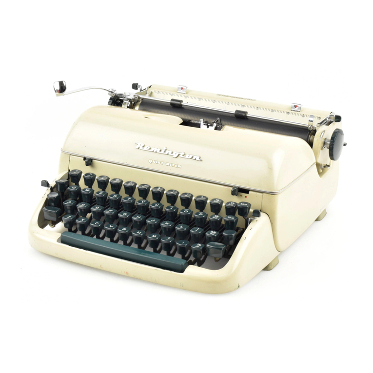
QWINT MSR742-I User manual


•
-
(B)

QWINT
INTERNATIONAL
INSTALLATION
MANUAL
Copyright
@ 1986 by
QWINT
DATA,
INC.
All
rights
reserved.
No
part
of
this
document
may
be
reproduced,
stored
in
a
retrieval
system,
or
transmitted,
in
any
form
or
by
any
means,
electronic,
mechanical,
photocopying,
recording,
or
otherwise
without
the
prior
written
permission
of
QWINT
DATA.
QWINT
DATA
reserves
the
right
to
make
changes
and/or
improvements
to
its
products
witho.ut
prior
notification,
and
without
incurring
any
obligation
to
incorporate
such
changes
or
improvements
in
units
previously
sold
or
shipped.
The names
QWINT,
COLLINEAR
7,
and
DIRECT
MOTOR
FEEDBACK
are
trademarks
of
QWINT
DATA,
INC.
QWINT
DATA,
INC.
3455
Commercial
Avenue
Northbrook,
Illinois
60062
TELEPHONE:
(312)
564-0910
TELEX:
27-0498
FAX:
(312)
564-4714
Printed
in
the
United
States
of
America.
ii

QWINT
INTERNATIONAL INSTALLATION
MANUAL
TABLE
OF
CONTENTS
CHAPTER
TITLE
PAGE
1.
GENERAL
INFORMATION. • • • • • • • • • • • • • • • •
1-1
2.
1.1
Features.
• • • • • • • • • • • • • • • • • • •
1-1
1.2
Physical
Size.
• • • • • • • • • • • • • • • •
1-1
1.3
Environmental
Requirements.
• • • • • • • • • •
1-2
ELECTRICAL
CONNECTION
•
•.•.
2.1
Power
Line
••••••••
2.2
Signals
•••••••••
. . . . . . . . . . .
. . . . . . . . . . .
2-1
2-1
2-3
3.
TERMINAL
CONFIGURATION. . . . . . • • • . • • . • •
3-1
4.
3.1
Keyboard.
• • • • • • • • • • • • • • • • • • •
3-1
3.2
Status
Report.
• • • • • • • • • • • • • • • •
3-2
3.3
Programming
Nationality,
Modem
Style,
and
Answerback
•••••••••••
PRIMARY
EIA
INTERFACE DESCRIPTION
••
. . . . . .
3-5
4-1
5.
PAPER
ROLL
SIZE.
. . . . • . . . . . • . . . • . • .
5-1
5.1
Paper
Supply
Shaft.
• • • • • • • • • • • • • •
5-1
5.2
Paper
Roll
Brackets.
• • • • • • • • • • • • •
5-1
6.
ADJUSTING
THE
ACOUSTIC CUPS
••
6-1
APPENDIX
A.
KEYBOARD
LAYOUTS. • • • • • • • • • • • • •
A-1
CCITT
#5,
United
States.
• • • • • • • • • • • • • •
A-1
CCITT
#5,
United
Kingdom.
• • • • • • • • • • • • •
A-1
CCITT
#5,
Finlan,d.
• • • • • • • • • • • • • • •
A-1
CCI
TT
#5,
Norway'·•
• • • • • • • • • • • . . . .
A-2
CCITT
#5,
Denmark..
• • • . . . . . . . . . .
A-2
CCITT
#5,
Sweden
-
•.
• • • • • • • • • • • • • • • • .
A-2
CCITT
#5,
Germany.
• • • • • • • • • • • • • • • • •
A-3
CCITT
#5,
French
Canada.
• • • • • • • • • • • •
A-3
CCITT
#5,
France.
• • • • • • • • • • • • •
A-3
CCITT
#5,
Spain.
• • • • • • • • • • • • • • • • • •
A-4
CCITT
#5,
Italy.
• • • • • • • • • • • • • • • • • •
A-4
Universal
CCITT
#2
(Baudot).
• • • • • • • • • •
A-4
International
Keycap
Locations
• • • • • • • • •
A-5
APPENDIX
B.
TERMINAL STATUS REPORTS
Switched
Network
Timeshare.
• • • • • • • • • • • •
B-1
Store/Forward
Switched
Network.
• • • • • • • • • •
B-2
Switched
Network/Telex@
110
• • • • • • • • • • • •
B-3
Switched
Network/Telex@
300
• • • • • • • • • •
B-4
Direct
1200
Baud.
• • • • • • • • • • • • • • • • •
B-5
iii
QWINT
INTERNATIONAL
INSTALLATION
MANUAL
Information
contained
in
this
manual
is
applicable
to
the
following
Qwint
Teleprinter
Models:
APPLICABILITY
CHART
D
MODEL
NUMBER
VERSION
REVISION
MSR742
-16B 5 A
or
later
MSR743
-16B 5 A
or
later
MSR744
-16B 5 A
or
later
MSR745
-16B 5 A
or
later
You
can
determine
the
model,
software
version,
and
revision
of
your
teleprinter
by
executing
TEST
4.
See
the
Programmer
Reference
Manual (PRM4I)
for
instructions
on
use
of
the
TEST
mode.
iv

QWINT
INTERNATIONAL
INSTALLATION
MANUAL
CRAPTER
l,
GENERAL
INFORMATION
1.1
Features
The
Qwint
Personal
Communications
Terminal
.contains
the
following
primary
elements:
- A
dot
matrix
plain
paper
printer
-
An
office
typewriter
quality
keyboard,
which
can
be
configured
to
10
different·international
use
character
sets
and
is
available
in
a CCITT #5 (ASCII)
layout
or
a
CCITT
#2
(Baudot)
configuration.
-
An
internal
memory
which
-
has
a
work
area
for
use
in
inputing
or
editing
a
message
or
character
string
-
has
13
programmable
keys
(areas)
to
store
messages
or
character
strings
for
later
transmission
or
later
editing
-
An
internal
answerback
-
An
internal
Bell
103/CCITT
V.21
compatible
modem
(MSR-744/45
models
only)
-
An
auto-ranging
power
supply
which
accepts
a
wide
range
of
voltages
and
frequencies
The
international
models
of
the
Qwint
teleprinter
are
designed
for
maximum
flexibility.
This
manual
describes
how
to
configure
the
terminals
and
select
options,
so
that
they
can
operate
efficiently
in
a
wide
range
of
applications.
1.2
Physical
Size
Figure
1-1
shows
the
teleprinter
dimensions
and
weight
for
installation
planning.
When
selecting
a
location
for
the
unit,
allow
enough
space
behind
it
so
that
paper
rolls
can
be
changed
conveniently.
1-1

QWINT
INTERNATIONAL INSTALLATION
MANUAL
CHAPTER
1.
GENERAL
INFORMATION
(Cont'd)
1.2
Physical
Size
(Cont'd)
FIGURE
1-1.
TELEPRINTER DIMENSIONS
AND
WEIGHT
1.3
Environmental
Requirements
1.
Operating
Temperature:
40
to
105
degrees
Fahrenheit.
(5
to
40
degrees
Centigrade).
2.
Airflow
Requirements:
None.
Natural
convection
satisfies
all
cooling
requirements.
3.
Relative
Humidity:
5
to
95%
noncondensing.
4.
Storage
Temperature:
-5
to
155
degrees
Fahrenheit.
(-20
to
70
degrees
Centigrade).
5.
Elevation
Restrictions:
7000
feet
(2100
meters).
1-2

QWINT
INTERNATIONAL
INSTALLATION
MANUAL
CHAPTER
2.
ELECTRICAL
CONNECTION
2.l
Power
Line
The
power
entry
connection
is
provided
tia
a
3-wire
grounded
connector
at
the
end
of
an
8
foot
(2.5
m)
power
cord.
This
should
be
connected
to
a
3-wire
grounded
socket
providing
power
which
meets
the
following
requirements:
Voltage:
Frequency:
Teleprinter
Power
Requirements
93
to
264
VAC
47
to
400
Hz
Configuration:
Balanced
or
Unbalanced
(switch
selectable)
0.6
A maximum
at
115
VAC
Power
Drain:
Figure
2-1
shows
diagrams
of
balanced
and
unbalanced
power
line
configurations.
One
leg
of
an
unbalanced
line
(Figure
2-lB)
is
connected
to
earth
ground.
In
a
balanced
line
(Figure
2-lA)
both
legs
are
hot.
A B
BALANCED
LINE
AC
e
POWER
rv
I I
SOURCE
"-
______
H_OT_·---<
HOT
[Ii
AC
POWER
SOURCE
QM21O
GND
I
~
_I
LJ
THREE-PRONG
ELECTRI.CAL
OUTLET
UNBALANCED
LINE
HOT
I'
GND
I
~
j__
L_j
THREE-PRONG
ELECTRICAL OUTLET
FIGURE
2-1.
POWER
LINE
CONFIGURATIONS
Determine
the
configuration
of
your
power
line
and
set
the
Balance/Unbalance
switch
accordingly.
(See
Figure
2-2.)
2-1

QWINT
INTERNATIONAL
INSTALLATION
MANUAL
CHAPTER
2.
ELECTRICAL
CONNECTION
(Cont'(l)
2.1
Power
Line
(Cont'd)
oe:=Jo
QM209
BALANCED
UNBALANCED
FIGURE
2-2.
LINE
BALANCE
SWITCH
Table
2-1
shows
the
definition
of
the
conductors
in
the
unit
power
cord
vs.
the
balance
swLtch
setting.
TABLE
2-1.
LINE
BALANCE
SWITCH
SETTINGS
SWITCH
SETTING
LINE
CORD
CONDUCTOR
BALANCED
UNBALANCED
BLUE
HOT HOT
BROWN
HOT
NEUTRAL
GREEN
EARTH EARTH
GROUND GROUND
Teleprinters
are
supplied
with
a
3-prong
plug
suitable
for
North
American
115V
connections.
(See
Figure
2-3.)
For
use
outside
North
America,
it
may
be
necessary
to
remove
the
115V
plug
and
substitute
a
new
plug
which
is
compatible
with
your
local
power
mains.
In
wiring
up
your
plug,
please
observe
the
color
code
of
Table
2-1.
2-2

QWINT
INTERNATIONAL
INSTALLATION
MANUAL
CHAPTER
2.
ELECTRICAL
CONNECTION
(Cont'd)
2.1
Power
Line
(Cont'd)
QM204
FIGURE
2-3.
THREE-PRONGED
PLUG
The
teleprinter
contains
an
auto-ranging
power
supply
which
will
automatically
accept
any
input
voltage
from
93
to
264
volts
with
no
switch
or
jumper
settings
necessary.
The
power
switch
for
the
terminal
is
at
the
left
rear
of
the
unit.
When
the
unit
is
turned
ON,
the
"PWR"
indicator
lamp
should
glow
bright
red.
As
power
is
applied,
the
carrier
should
move
to
the
left
until
it
reaches
the
left
hand
margin.
This
homes
the
carrier
in
preparation
for
printing.
2.2
Signals
MSR-744
and
745
models
contain
an
internal
modem.
This
modem
is
intended
for
telephone
communications
only
and
should
not
be
used
for
Telex
service.
The
modem
may
be
used
with
the
Model
CUP
301
acoustic
adapter
or
it
may
be
connected
directly
to
the
telephone
lines
via
either
of
the
RJ-11
jacks
on
the
teleprinter
back
panel.
NOTE:
Be
sure
to
have
the
necessary
approvals
from
the
telephone
company,
communications
authority,
or
PTT
before
connecting
to
the
telephone
network.
Table
2-2
gives
the
RJ-11
connector
signals
in
case
it
is
necessary
to
convert
to
another
type
of
plug.
TABLE
2-2.
RJ-11
CONNECTOR
SIGNALS
Connector
Pin
Jack
1
Jack
2
3
Tip
Ring
4
Ring
Tip
2-3

QWINT
INTERNATIONAL
INSTALLATION
MANUAL
CHAPTER
2.
ELECTRICAL
CONNECTION
(Cont'd)
2.2
Signals
(Cont'd)
The
internal
modem
is
compatible
with
Bell
103
and
CCITT
V.21
FSK
signalling
schemes.
Modem
type
and
long
(or
short)
space
disconnect
are
prompted
from
the
teleprinter
keyboard
via
the
PRG
key.
(See
Section
3.2
for
instructions
on
the
use
of
the
PRG
key.)
When
electrically
connected
to
the
telephone
network,
the
International
FSK
modem
may
originate,
answer,
automatically
pulse
dial
or
automatically
answer
in
either
the
Bell
103
or
CCITT
V.21
mode. The
modem
will
also
work
with
the
acoustic
coupler
option.
With
the
acoustic
option,
originate
or
answer
operation
is
selected
by
a
switch
on
the
coupler.
NOTE:
Both
the
power
and
the
telephone
cables
should
be
routed
such
that
there
is
no
opportunity
for
them
to
become
accidentally
disconnected
by
someone
stepping
or
tripping
on
them.
Special
thought
and
care
should
be
given
to
this
at
the
installation,
since
the
teleprinter
is
a
small
desktop
personal-sized
unit.
2-4

QWINT
INTERNATIONAL
INSTALLATION
MANUAL
CHAPTER
3.
TERMINAL
CONFIGURATION
3.1
Keyboard
Layout
International
models
are
available
with
either
of
two
keyboards:
a
universal
CCITT #2
(Baudot)
arrangement,
or
a CCITT #5
(ASCII)
configuration.
These
keyboards
are
illustrated
in
Appendix
A.
The
Baudot
keyboard
is
suitable
for
use
world-wide
without
keycap
substitution.
The
national
character
variants
are
represented
on
the
Baudot
keyboard
by
the
symbols
D,
8,
and
IZf
which
appear
on
the
top
row
of
the
keyboard.
These
keys
take
on
specific
national
character
meanings
depending
on
which
national
character
set
the
machine
is
prompted
for.
ASCII
(CCITT
#5)
teleprinters
are
normally
supplied
with
a
United
Kingdom
keyboard
layout
and
character
set.
In
case
it
is
necessary
to
change
this
layout,
a
keycap
remover
and
a
full
set
of
optional
keycaps
are
supplied
with
each
ASCII
international
teleprinter.
The
complete
set
of
keyboard
layouts
supported
by
the
terminal
is
given
in
the
Appendix
of
this
document.
Figure
3-1
shows
how
to
use
the
keycap
remover.
Simply
use
the
remover
to
grasp
the
underside
of
the
keycap,
then
pull
up.
Press
the
new
keycap
into
place.
Table
3-1
shows
which
models
are
shipped
with
ASCII
(CCITT
#5)
keyboards
and
which
are
shipped
with
Baudot.
TABLE
3-1.
TYPE
OF
KEYBOARD
PROVIDED
CCITT
#2
CCITT
#5
TERMINAL
BAUDOT
ASCII
MSR-742
yes
MSR-743
MSR-744
MSR-745
You
will
note
below
that
these
machines
can
be
mode,
for
either
an
ASCII
or
Baudot
keyboard.
flexibility
allows
machines
to
be
changed
from
the
other
by
exchanging
the
terminal
keyboard,
need
to
replace
program
memory
chips.
yes
yes
yes
set
up,
in
program
This
software
one
CCITT
code
to
but
without
the
These
machines
can
also
be
programmed
to
communicate
in
either
CCITT #2
or
#5
code
irrespective
of
the
keyboard
in
use.
Separate
programming
decisions
are
provided
for
the
Keyboard
Option
and
for
the
Communications
Option.
A
machine
with
a CCITT
#5
(ASCII)
keyboard,
which
is
set
up
to
communicate
in
CCITT
#2
(Baudot),
will
automatically
convert
keystrokes
into
the
equivalent
Baudot
characters,
and
vice
versa.
(Because
some
ASCII
characters
do
not
have
Baudot
equivalents,
they
are
ignored
and
not
transmitted.
See
the
User's
Guide
for
details.)
3-1

QWINT
INTERNATIONAL INSTALLATION
MANUAL
CHAPTER
3,
TERMINAL
CONFIGURATION
CHAPTER
3.
TERMINAL
CONFIGURATION
(Cont'd)
3.1
Keyboard
Layout
(Cont'd)
FIGURE
3-1.
3.2
Status
Report
USING
THE
KEYCAP
REMOVER
The
terminal
character
set
can
be
determined
by
using
the
STAT
(status)
key
and
modified
by
using
the
PRG
(program)
key.
To
check
the
present
terminal
configuration:
1.
Place
the
unit
OFF-LINE
(green
LINE
lamp
off).
(Use
the
DIAL/LINE
key
to
turn
the
machine
on
or
off
line.)
2.
Print
a
STATUS
report.
While
holding
down
the
Control
(CTRL)
key,
press
the
key
marked
"STAT"
(Status).
Table
3-2
shows
the
status
report
of
unit
set
to
the
U.S.
character
set.
3-2

QWINT
INTERNATIONAL INSTALLATION
MANUAL
CHAPTER
3.
TERMINAL
CONFIGURATION
(Cont'd)
3.2
Status
Report
(Cont'd)
TABLE
3-2.
TELEPRINTER
STATUS
REPORT
Typing
Options
PERMITTED OPTIONS
Print
intensity=
8
••••••••••••
0-15
LCV
time=
15
deciseconds
•••••••••
1-127,
[0=NO
LCV]
Phone:1234567890:11234
••••••••••
16
digits,1or=2
SEC
Lines/inch=
6
••••••••••••••
4,
6,
8
Half
lines/LF
= 2 •
••••••••••••
2,
3,
4
Characters/inch=
12
•••••••••••
10, 11, 12,
13, 15,
17,
20
Left
margin=
0
characters
•••••••
0,
7xCPI-16
Line
length=
83
characters
•
••....
15,
7xCPI-1
Printer
Options
On
receipt
of
CR
the
printer
On
receipt
of
LF
the
printer
On
receipt
of
VT
the
printer
On
receipt
of
FF
the
printer
will
CR
.
will
LF .
will
Slew
will
Slew
••
CR,
CR
LF
••
LF,
CR
LF
1"
NL,
SLEW
1"
2"
NL,
SLEW
2",
FF
TO
MARKER,
FF
TO
TOP
OF
PAGE
Top
margin=
3
lines
•
Page
length=
60
lines
•
•••••••
0-255
• • • • • •
0-255
Keyboard
Options
New
line
key=>
CR
LF
•••••••••••
CR,
LF,
CR
LF,
CR
LF
DEL
Keyboard
Format=
ASCII
••••••••••
ASCII,
Baudot
Character
Set=
USA
••••••••••••
USA,
UK,
Finland,
Norway/Denmark,
Sweden,
Germany,
French
Canada,
France,
Spain,
Italy
Communication
Options
Terminal
Connects
through
EIA
•••
Signal
protocol
is
Full
RS232
••
• • • •
EIA,
Internal
Modern
•••
RD/TD,
RS232,
two
wire
neutral,
103,
V.
2
Baud
rate=
300
••••••••••••••
45-1200
Serial
data
format
is
CCITT #2
••••••
2,
5
Parity
is
EVEN
••••••••••••••
EVEN,
ODD,
MARKING,
SPACING
Data
error
detection
is
ON
••••••••
ON, OFF
Local
echo
is
ON
•••••••••••••
ON, OFF
Character
initiated
disconnect
is
NONE
••
NONE,
EOT
3-3

QWINT
INTERNATIONAL
INSTALLATION
MANUAL
CHAPTER
3.
TERMINAL
CONFIGURATION
(Cont'd)
3.2
Status
Report
(Cont'd)
CTS/SRTS means
printer
IS
NOT
ready
•••
IS,
IS
NOT
Data
IS
NOT
transmitted
at
6
cps
•••••
IS,
IS
NOT
Terminal
IS
captured
by
incoming
call
•••
IS,
IS
NOT
Terminal
is
captured
on
receipt
of
5
rings
••••••••••••••••
1-10
Terminal
IS
NOT
controlled
by
DC4/DC2
•••
IS,
IS
NOT
Memory
Options
Memory
transmission
IS
NOT
blocked
by
CR
LF.
• • • • • • • • • • • •
IS,
IS
NOT
Data
IS
NOT
transmitted
from
memory
on
receipt
of
DCl
•••••••••••••
IS,
IS
NOT
Answerback
Options
Answerback
IS
NOT
transmitted
at
connect
time
• • • • • • • • • • • • • • • • • •
IS,
IS
NOT
Answerback
=
:Qwint
NBRK:
= :
•••••••
Up
to
20
characters
3.3
Programming
Char
Set,
Modem
Style,
&
Answerback
Operator
selectable
options
and
the
answerback
are
changed
by
means
of
the
PRG
(Program)
key.
The
answerback
may
need
to
be
approved
before
it
can
be
used
in
network
communications.
1.
Press
CTRL
PRG.
2.
Answer
"N" (no)
to
any
options
that
are
not
to
be
changed;
Answer
"Y"
(yes)
and
enter
changes
to
any
options
that
are
to
be
changed.
3.
If
the
answerback
is
to
be
changed,
answer
"STORE?"
with
a
CTRL
z
keystroke.
4.
The
machine
will
print
the
current
answerback
followed
by"?"
5.
Answer
with
an
"N".
6.
The
machine
will
prompt
for
a new
answerback
and
will
automatically
terminate
entry
after
20
characters.
Use
the
format
described
on
the
following
pages.
7.
Machine
will
print
"STORE?" Answer
"yes"
to
update
the
options
and/or
the
answerback.
3-4

QWINT
INTERNATIONAL
INSTALLATION
MANUAL
CHAPTER
3.
TERMINAL
CONFIGURATION
(Cont'd)
3.3
Programming
Char
Set,
Modem
Style,
&
Answerback
(Cont'd)
NOTE:
The
terminal
character
set
changes
as
soon
as
it
is
received
during
the
prompting
sequence.
After
this,
all
key
locations
on
the
keyboard
take
on
their
new
definitions.
For
instance,
if
the
keyboard
layout
is
changed
from
U.S.
to
Germany
("QWERTY"
to
"QWERTZ"),
the
"Y"
and
"Z"
keys
will
be
interchanged.
The
operator
must
press
the
"Y"
key
in
its
new
location
when
answering
yes
to
the
remaining
questions
in
the
prompting
sequence.
If
the
keyboard
is
changed
from
ASCII
to
Baudot,
the
Program/Status
keys
will
also
change
locations.
(See
keyboard
layouts
in
Appendix
A.)
.3-5

QWINT
INTERNATIONAL
INSTALLATION
MANUAL
CHAPTER
4.
PRIMARY
EIA
INTERFACE
DESCRIPTION
(Cont'd)
4
Request
to
Send
5
Clear
to
Send
6
Data
Set
Ready
The
Request
to
Send
conductor
is
used
to
signal
the
data
transmission
equipment
to
condition
itself
for
data
transmission.
The
RTS
conductor
is
ON
when
the
terminal
is
in
the
LINE
mode
and
OFF
when
the
terminal
is
in
the
LOCAL
mode.
The
Clear
to
Send
conductor
is
used
to
signal
the
terminal
that
the
data
transmission
equipment
is
capable
of
sending
data.
The
CTS
circuit
can
optionally
be
recognized
or
ignored
as
a
condition
for
data
transmission
on
the
TD
circuit.
If
the
CTS
circuit
is
optionally
recognized,
CTS
must
be
ON
for
data
transmission
to
occur
on
the
TD
circuit.
If
the
CTS
circuit
is
optionally
ignored,
the
state
of
the
CTS
circuit
does
not
affect
trans-
mission
on
the
TD
circuit.
If
the
CTS
circuit
is
recognized,
its
logical
state
can
be
inverted
from
its
normal
state
by
terminal
option:
Normal
ON: +12V
Inverted
ON:
-12V
The
Data
Set
Ready
conductor
is
used
to
signal
the
terminal
that
the
communication
equipment
is
connected
to
the
communication
channel.
The
Data
Set
Ready
circuit
must
be
ON
for
the
DTR
circuit
to
remain
ON.
Disconnect
will
occur
if
DSR
goes
OFF.
4-2

QWINT
INTERNATIONAL
INSTALLATION
MANUAL
CHAPTER
4.
PRIMARY
EIA
INTERFACE
DESCRIPTION
(Cont'd)
7
8
Signal
Ground
Received
Line
Signal
Detector
If
the
terminal
has
been
optioned
for
the
capture
mode,
DSR
going
OFF
will
cause
DTR
to
go
off
until
DSR
goes
ON.
The
terminal
will
be
removed
from
the
LINE
mode
and
placed
in
the
LOCAL
mode.
When
the
terminal
has
been
placed
in
the
LOCAL
mode,
DTR
will
be
turned
on
as
a
condition
for
capture
by
activity
on
the
RI
circuit
or
on
the
RD
circuit.
If
the
terminal
has
been
optioned
for
the
non-capture
mode,
DSR
going
OFF
will
cause
DTR
to
go
off
until
DSR
goes
ON.
The
terminal
will
remain
in
the
LINE
mode.
The
Signal
Ground
conductor
es-
tablishes
a common
ground
reference
potential
for
all
interchange
circuits,
except
Protective
Ground.
The
Received
Line
Signal
Detector
is
used
to
signal
the
terminal
that
a
carrier
frequency
has
been
placed
on
the
communica-
tion
link
and
that
data
can
be
or
is
being
sent
to
the
terminal.
The
RLSD
circuit
must
be
ON
for
the
terminal
to
receive.
A
character
for
character
check
of
RLSD
is
made
for
the
ON
state.
A
transition
of
RLSD
from
ON
to
OFF
will
inhibit
received
data,
but
will
not
disconnect
the
terminal.
If
the
terminal
is
in
the
capture
mode,
a
transition
of
RLSD
from
OFF
to
ON
and
presence
of
data
on
the
RD
circuit
will
cause
the
terminal
to
automatically
be
placed
in
the
LINE mode
from
the
LOCAL
mode.
4-3

QWINT
INTERNATIONAL
INSTALLATION
MANUAL
CHAPTER
4.
PRIMARY
EIA
INTERFACE
DESCRIPTION
(Cont'd)
13
19
20
22
Secondary
Clear
to
Send
Secondary
Request
to
Send
Data
Terminal
Ready
Ring
Indicator
Not
used.
The
Secondary
Request
to
Send
conductor
is
used
as
an
optional
data
pacing
circuit.
When
the
data
pacing
option
is
enabled,
an
SRTS
ON
state
indicates
that
data
transfer
can
occur.
When
SRTS
is
in
the
OFF
state,
the
terminal
is
not
capable
of
receiving
data
transfer.
The
Data
Terminal
Ready
conductor
is
used
to
indicate
the
terminal's
readiness
to
communi-
cate
on
the
communication
link.
The
DTR
circuit
will
be
placed
in
the
ON
state
when
the
terminal
is
placed
in
the
LINE mode.
If
the
terminal
is
in
the
capture
mode, a
transition
of
OFF
to
ON
of
DTR
will
occur
upon
a
transi-
tion
of
RI
from
OFF
to
ON
when
connected
to
an
external
modem,
or
upon
the
presence
of
data
on
the
RD
circuit,
and
DSR
or
RLSD
ON
when
connected
back-to-back
with
another
EIA
port.
DTR
will
be
prevented
from
turning
ON
if
Low
Paper
or
Paper
Out
states
exist
in
the
terminal.
If
DTR
is
ON,
and
either
Low
Paper
or
Paper
Out
occurs,
DTR
will
be
turned
OFF,
causing
a
disconnect,
if
the
terminal
is
ON-LINE.
The
Ring
Indicator
is
used
to
signal
the
terminal
that
the
communication
link
is
receiving
a
ringing
signal.
If
the
terminal
is
in
the
capture
mode,
it
will
respond
by
turning
DTR
ON.
The
terminal
has
a
programmable
option
to
respond
to
RI
after
N
rings.
4-4

QWINT
INTERNATIONAL
INSTALLATION
MANUAL
CHAPTER
5.
PAPER
SIZES
5.1
Paper
Supply
Shaft
Teleprinters
are
supplied
with
1
roll
of
8-7/16
inch
(214
mm)
wide
paper,
so
they
can
be
set
up
and
operated
immediately.
The
teleprinters
are
capable
of
accepting
three
different
paper
roll
widths:
1.
8-7/16
inches
(214
mm)
2.
210
mm
3.
6
inches
(152
mm)
Figure
4-1
shows
the
corresponding
pairs
of
grooves
in
the
paper
supply
shaft
that
will
accommodate
paper
rolls
of
these
widths.
FIGURE
5-1.
PAPER
SUPPLY
SHAFT
5.2
Paper
Roll
Brackets
The
position
of
the
right
hand
paper
roll
bracket
is
changed
to
accommodate
paper
rolls
of
differing
widths.
(The
left
hand
bracket
stays
fixed,
since
its
location
determines
the
location
of
the
left
margin
on
the
printed
page.)
The
right
hand
paper
roll
bracket
is
held
in
place
with
a
single
7
mm
cap
screw.
Figure
5-2
shows
where
to
position
the
cap
screw
and
bracket
for
paper
rolls
of
differing
widths.
5-1
This manual suits for next models
3
Table of contents