manuals.online logo
Brands
  1. Home
  2. •
  3. Brands
  4. •
  5. Olivetti
  6. •
  7. Typewriter
  8. •
  9. Olivetti LINEA 88 User manual

Olivetti LINEA 88 User manual

Other Olivetti Typewriter manuals

Olivetti ETP 630 User manual

Olivetti

Olivetti ETP 630 User manual

Olivetti 900X User manual

Olivetti

Olivetti 900X User manual

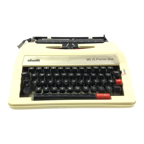
Olivetti MS 25 Premier plus User manual

Olivetti

Olivetti MS 25 Premier plus User manual

Olivetti ETP 630 User manual

Olivetti

Olivetti ETP 630 User manual

Olivetti Linea 198 User manual

Olivetti

Olivetti Linea 198 User manual

Popular Typewriter manuals by other brands

IBM Selectric II operating instructions

IBM

IBM Selectric II operating instructions

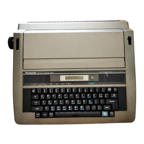
Panasonic KX-R530 - Electronic Typewriter operating instructions

Panasonic

Panasonic KX-R530 - Electronic Typewriter operating instructions

Brother AX-425 parts reference list

Brother

Brother AX-425 parts reference list

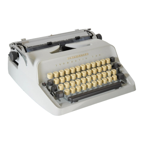
Scheidegger TYPOMATIC-TMS Instruction handbook

Scheidegger

Scheidegger TYPOMATIC-TMS Instruction handbook

Siemens 1000 CA operating instructions

Siemens

Siemens 1000 CA operating instructions

Remington Rand Inc. Noiseless 10 Mechanical Instructions

Remington Rand Inc.

Remington Rand Inc. Noiseless 10 Mechanical Instructions

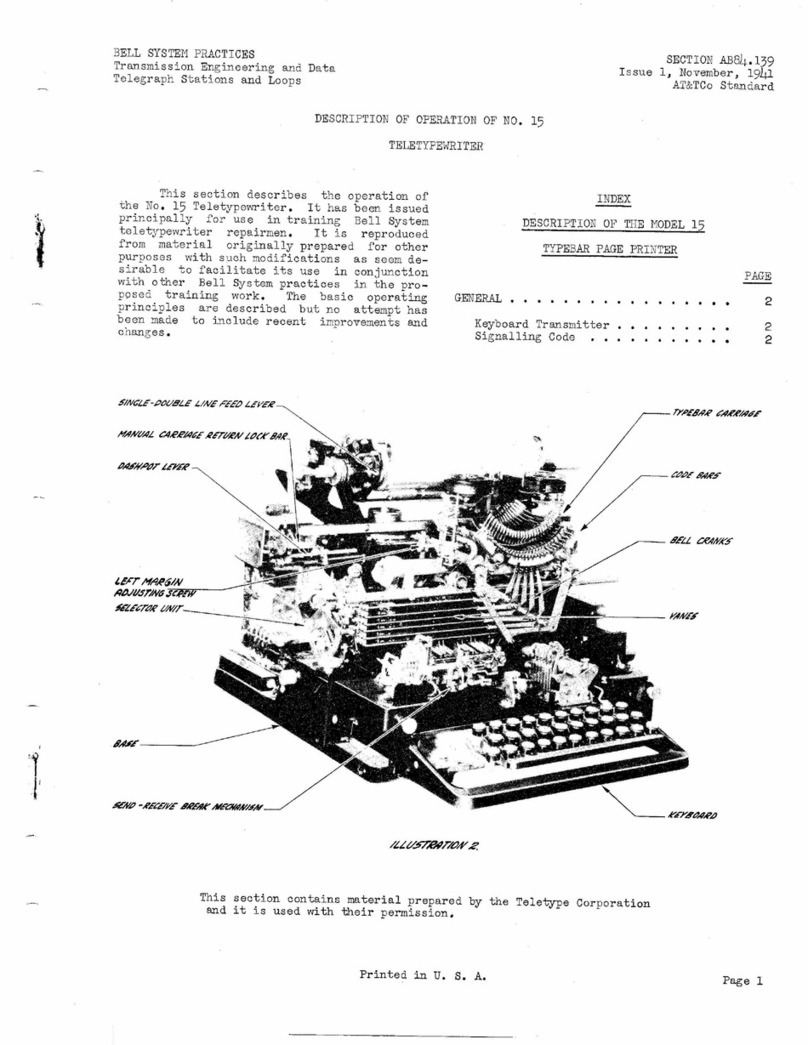
Teletype 15 Description & operation

Teletype

Teletype 15 Description & operation

Panasonic KX-E50 Operator's instruction manual

Panasonic

Panasonic KX-E50 Operator's instruction manual

IBM Selectric III Troubleshooting

IBM

IBM Selectric III Troubleshooting

Brother SX-4000 user guide

Brother

Brother SX-4000 user guide

Brother AX-10 instruction manual

Brother

Brother AX-10 instruction manual

Remington TRAYEL-RITER instruction manual

Remington

Remington TRAYEL-RITER instruction manual

Brother AX-325 user guide

Brother

Brother AX-325 user guide

Brother CM-1000 user guide

Brother

Brother CM-1000 user guide

Singer 1501 Operator instructions

Singer

Singer 1501 Operator instructions

Smith Corona Memory Correct user manual

Smith Corona

Smith Corona Memory Correct user manual

Silver Reed Portable Series instruction manual

Silver Reed

Silver Reed Portable Series instruction manual

Torpedo 18 instructions

Torpedo

Torpedo 18 instructions

manuals.online logo
manuals.online logoBrands
  • About & Mission
  • Contact us
  • Privacy Policy
  • Terms and Conditions

Copyright 2025 Manuals.Online. All Rights Reserved.

OLIVETTI STANDARD
TYPEWRITER SERVICE
MANUAL
(FOR ALL OLIVETTI STANDARD MANUAL
TYPEWRITERS)
Printed
by
Olivetti November 1973
I I~ICA
08
A~ln
IlTUt:DC
L,..11"
Lr \ U r \1
LI
\..J
I I I
L
n.V
\
Ernie Jorgenson - Office Machine Americana - 1740 8irch Ave
Lewiston, Idaho 83501 USA - http://officemachinemanuals.com
LI NEA 88 [ W Y
Alignlng Scale Adjustments
0...
123
Allgnlng Scales (Transparent) 72
Backspace Adjustment 128
Backspace Pavl 81
Bankinq Adjustment 124
Bearlng (carrlage front rail) '" 74
Carrlage Ball Bearlng Cages 88
Carrlage Release Frame 86
Dravband (carrlage) 73
Escapement Body 77
Escapement Oog Release Ouring Tabulatlon Adjustment .
Escapement Fix Oog Lim\t Screw Adjustment .
Escapement Rack ........•................................
Escapement Rack Adjushent ................•.............
Escapement Release Rocker .
Escapement Tr\p (type bar) Adjustment .
Feed Roll Pressure Spr\ngs .
Line Lock Adjus
tmerrls .....•.............................
Ll ne Space Adjus tnents .
l
i
ne Space Mechanlsm .
Machlne Si de Walls : .
Marg\ n Re1ease Shaft .
Margln Release Shaft (rest pcs
i
t
i
on) Adjustment '.
Margln Release Shaft Plunger - .
Marg\ n Stops .
Platen
&
Plai
en Knobs .
Platen, Left Hand Shaft .
Platen Lock Lever Adjustment .
Ribbo~ Feed Adj us rments .
Ri bbon Feed ~chets ' '." " .
Ribbon Guide .
Ribbon l.i
f
l Aduating Lever .
Ribbon LiH Adjushent .
Ribbon Reverse Adjustments .
Ring
&
Platen Adjustment .
Space Bar Trip Adjustment .
Segment Free Travel Adjustment .
Shift Lock Key Adjustment .
Tab Sett\ng F\nger Adjustment .
Tabulation Release Adjustment .
Tabulator Centr\fugal 8rake .
Tabu 1ator Stops .
Tabulator Stop Blades .
Type Act ion Mechanism .
Type on Feet
&
Motion Adjustments .
Universal Bar Adjustment .
Universal Bar (Escapement) .
Var\able (Plat en) .
126
112
75 119
87 169
66 110
122
80
68
82 129
84
83
67
89 111
117
li.
71
70
-70a 116
118
3
127
114
115
125
121
85
78
76
65 113
120
69
79
RING AND PLATEN ADJUSTMENT
6J
4J.-=:=-----~
3
.........
y
Segment in lover case
I
LJ
_ Check the ring and p13ten at both ends of Loosen the screws (4) on both the
the platan _asfoll_~w.~L . left and right hand brackets (2).
_ With a type bar held against the segment Hove the entire carriage assembly
stop ring, there should be a drag on two
~
back ar forth via the slots (A and
strips of bond paper (placed between the 8) as required. When the ring and
type and the platen) and very little drag platen is correct, position the
on ane strip of paper. eccentric stud
(3)
against the
br-acke
t
(2), left and right.
yes A good ring and platen no
FFG condition exists for the ma
i
or- The ring and platen yes
.ity of the type bars is correct
FFG
no
If the platen is not parallel, adjust
the pla+e (1) back orforth as requir- Check the ring and platen again
ed.
Ihis
vill parallel the right end as described above
of the platen to the left end which is
fixed.
IV3al
(Continued from the previous page)
Check that the 1ine l oc k comb
(p)
062013K is
free by pushing it to
t
he right. Re1ease it,
and it must return with a snappy action so its
extension
(e)
1imits against +he side va l l as
shovn in fig.4
yes
p
--~-~-----.:-.. &.._ç~
062013K
C1ean and 1ubricate the mov-
ing parts of the comb
(fi g. 4)
With the extension (C) at rest against the
side wall, check that a11 the key 1evers
c1ear the prongs of the comb vi
t
h a sna l l
c1earance- (L), fi g:4 no Form the extension
(e)
to
r--~~
obtain the c1earance (L)
<J
PLATEN LOC K LEVER ADJUSTMENT
~
I
Y111
- Adjust the eccentric
unti1 a11 the play is
e1iminated
- Re-engage the feed rolls
- Re1ease the feed roll
re1ease 1ever
- Check that the p laten lock
lever (A) securely ho1ds the
p1aten without vertical p1ay
The platen has vertical
play
no
yes
The carriage is jammed
limit scre~
yes
- Remove the carriage assembly
- Loosen the lock nut and turn scre~
(A) counterclock~ise about 3 to 4
turns fi .1
Release the carriage
and adjust the limit
screw to obtain the
clearance of 0.1 to 0.2
mm as shown in fig.3
The fixed dog assy. has a
maximum play of 0.2 mm }----
-I
no
o
sere, ,
The carriage i s
st
í
11 jammed
no
Re-adjust the
scr
ev
A)
to obtain
t
he clearance
shcvn
in fig.3
Re-insla11
the
carriage
There has been a previous
ca l l in thi s area
)-----:r;<>-j
Remove the carriage assembly
and posilion il as shown in
fi g.l
Move the carriage until a toolh of the
escapement
vhe
e l is diredly under lhe
fixed dog (fig.2). In this p~silion.
rotate lhe fixed dog assy. with your
finger.
f
i
q.}, and check for a max.
clearance of 0.2 mm as sho~n in fig.3
yes
yes
Y127
TYPE ON FEET
&
MOTION ADJUSTMENTS
[Y113
I
- Segment in upper case
- Ribbon se1ector in b1ack
- Insert a piece of paper in
the machi ne
Type a11 upper case characters
and check that
t
he type. is on
feet (uni form density
t
op to
batiam)
yes The majority of
pri
nt
s on feet
no
If the majority of the type prints
"1i
çht
on
t
op",
l
over both screws
(A)
equa lly and vi ce versa, fi g.1
Using a strip
of
paper
as a
gauge,
check for an even
ho
ld
at
both
screws
(A),
figure
3
The motion is correct
(the characters a1ign
on the same base 1ine)
no
If the motion is short, raise
the upp'er screws (8) equally
and vice versa, fig.1
Using a strip of paper as a
gauge, check for an even ho ld
at both screws (8), fig.2
CD
CD
SEGMENT FREE TRAVEL ADJUSTHE~T
Y114
I
Tighten the adjust-
able arm set scre~
(8)
~
~--------------------~,
Segment
frame
Laasen the set scre~ (B)
af the adjustable arm
Free the mavemenl af lhe
segmenl
by
shifling lhe
end (A) af the segment
shift frame back ar forth
as required
Remove tap
caver
NOTE: If :r.e machine is
fastened to lhe desk, be
sure the T"slening scre~s
are tightE~Ed equally
Clean and lubricate the
segment br=cket bushings
Segmenl in 1over ·case
S~lFT LOCK KEY ADJUSTMENT
Ho1d the shift key
fu11
y
depressed
AI the same time, depress the
shifl 10ck key and check that
the s
t
ep (A) passes behind pin
(p)
w
ith a O. 2 to O.5 mm c1ea
r-
ance. ReI ease lhe keys
Repeat lhe lesl on lhe olher
shift 1ack key
The passing c1earances
are carrect
no
P
069006C
Adjust the pin (p) 1eft
)----ilIo-l
or righl as required
R IBBON REVERSE AOJUSTMENTS
CD
\Y118 \
+
.Reverse arn
--------~ _.J
?é'lerSe
Ar:n---i-'
Detent 1i nk
<J
- Manually shift He1eft reverse - Now shift the left reVEr~e arm to the 1eft
unt i 1 it limits açainst stop (A), fig.1
arm to the rigr,t unti1
í
t
limits - Al
t
hi s time check if He c1earance (l1) figo
) R"." the top
againsl stop (8) fig.1
cov er
H-_
Al lhis lime check the amount of
~
2 is equa1 to c1earance (L) i n fi g.1
clearance a
t
(l), fig.1
J
Form lhe righl r-eve+se arm at no The cl earance s (l and l1)
the shaded area shown in fig.2 are about ecua 1
yes
- Shift the 1eft reverse arm to the right unti1 i t - Shift lhe 1eft r ever se arm to the I ef]
1imits against stop (8) unti1
i
t
l
i
ni
i
s aqa ins
t
st op (A)
- Shift the detent 1ink 061238G fu11y to
tr.e
left - Shift the det ant l ink O~1238G f~lly to
and ho1d it there the righl and r.old i there
- Al this time check if lhe gap
(e
1) fig.~ is about - Check the amoun o
f
ça~
a
t
(e)
fig.3
equal to gap
(e)
fig.3
yes The gaps
(e
and
e
1)no Form the detent 1i nk 061238G at
FFG are abo ut equa 1 the shaded area shovn in fig.4
IY118a\
ESCAPEMENT RACK AOJUSTMENT
Remove the platen
and paper pans
~
Margin stops set at their
extreme positions
\
Move the carriage slowly baCK
and forth. Check that the rack
mesh to pinion is as deep as
possible without bottoming over
the entire length of the rack.
Maximum clearance between the
teeth is
0.2
mm (fig.1)*
.Ljw
yes The rack mesh to
pinion is correct
no
Loosen the escapement rack
scr evs and po s
i
t
i
on the rac k
as required
- Tighten the escapement
rac
k
scr-evs
j~/~
.~
ement rack scrells
*
Note: For checking the rack mesh to pinion~
_ Hold the escapement vnee l rigid
_ Jiqqle the carriage slightly IIhile checking the play
------.
UNIVERSAL
(nun)
BAR AOJUSTMENT (Equalization of Type Bar Trip)
IY120
I
A 5
NOTE: The Universal Bar (4) must be positioned so
that the bosses (A) of a11 the type bars (5) move
the
"un
Bar approximately the same amount
3
4
<>
- Manually raise a typê bar at the right end of the segment to the
type guide and observe when the escapement trip occurs
- 00 the same with a type bar at the left end of the segment, and
at the center
The escapement trip occurs when the type bars yes
Y169
are about the same distance from the platen
no
- Remove carriage assembly
- Loosen screws (2) and reposition the OU" Bar (4) by means
of the floating bushings (3) to equal ize the tr ip
yes
\
The IIU" Bar is free
no
- Loosen screws (2) friction tight, also loosen guide screw (1)
- Reposition the "U" Bar sl
i
çht
ly
to relieve the bind but still
maintain centralization