R.A.SH Tronics CHRYSLER PACIFICA User manual

2021©R.A.SHTronics Ltd.All rights reserved.
Reproduction by any means,electronic,graphics (GUI) or mechanical,includingphotocopying,recordingor by any information storage and retrieval
systemor translation in whole or partis NOTPERMITTED withoutwritten authorization fromR.A.SHTronics Ltd.
CHRYSLERPACIFICA MINIVAN
SECONDAYCONTROLS
INSTALLATIONGUIDE
LAST UPDATEDApril 13,2021
REV: 03

ChryslerPacificaMinivan
R.A.SHTronicsDepartment of R&D 2
TableofContents TOOURVALUEDCUSTOMER............................................................................................................................3
CUSTOMERCARECENTER................................................................................................................................3
ABSTRACT.......................................................................................................................................................3
USEFUL HINTS.................................................................................................................................................3
SECONDARYCONTROLSDEFENITIONS..............................................................................................................4
SYSTEMOVERVIEW.........................................................................................................................................5
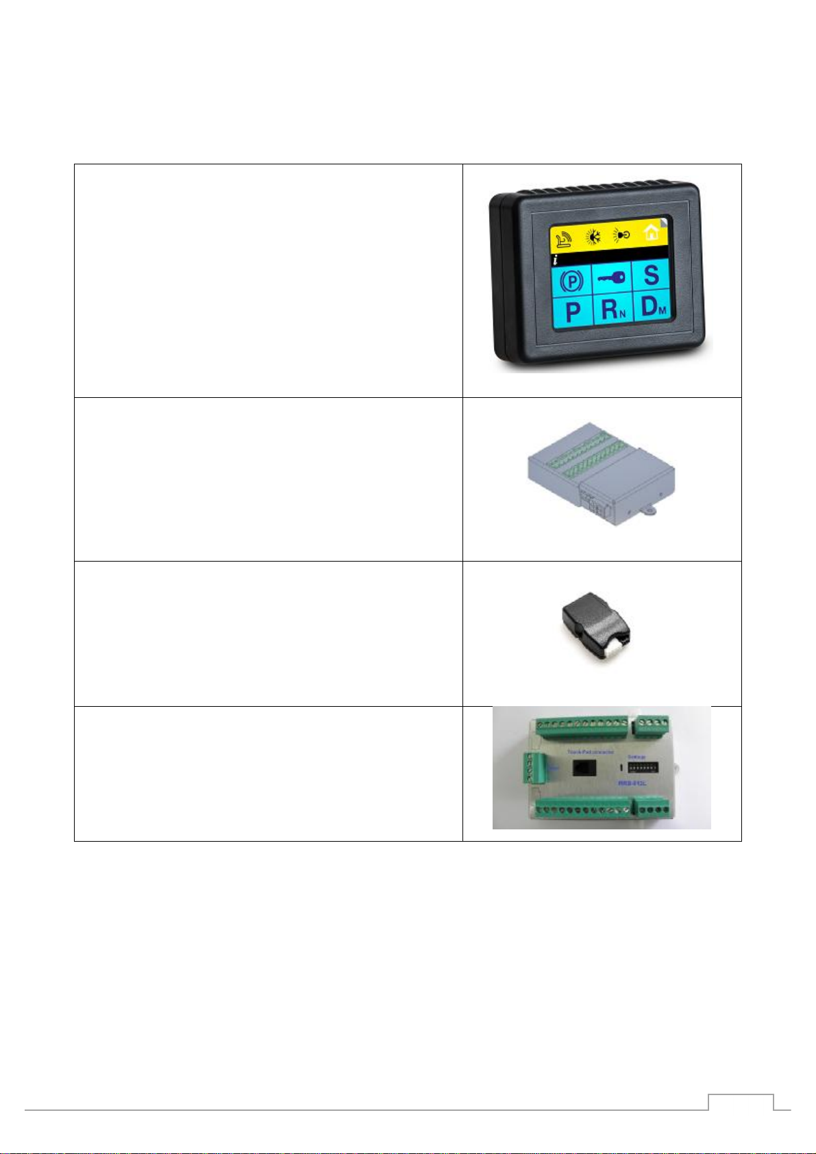
DESCRIPTION OF MAINCOMPONENTS..............................................................................................................6
DESCRIPTION OF THE MAIN COMPONENTSCONTINUED....................................................................................7
CAN-BUSGATEWAYMODULE...........................................................................................................................8
SHIFT BYWIRECANbusMODULE......................................................................................................................9
SHIFT BYWIRECANbusWIRING......................................................................................................................10
PUSHBUTTONSTART MODULE.......................................................................................................................11
Usingthestartstopfunction.......................................................................................................................11
Start/StopModificationProcedure..............................................................................................................11
ENGINESTART STOPWIRING.........................................................................................................................12
MULTI-FUNCTIONMODULE...........................................................................................................................13
HEADLIGHTSWIRING.....................................................................................................................................14
ELECTRONICPARK BRAKEWIRING..................................................................................................................15
HVAC, WINDOWS, MIRRORSMODULE............................................................................................................16
HAZARD WARNINGLIGHTS............................................................................................................................17
EGRESS MODULEWIRING..............................................................................................................................18
VOICE SCAN WIRING......................................................................................................................................19
USINGTHEHVAC...........................................................................................................................................20
USINGTHECRUISECONTROL.........................................................................................................................21
APPENDIX.....................................................................................................................................................23

ChryslerPacificaMinivan
R.A.SHTronicsDepartment of R&D 3
TO OURVALUEDCUSTOMER
Itisourintention toprovideourvaluedcustomerswiththebestdocumentation possibletoensuresuccessful use
ofourproducts.Wewill continuetoimproveourpublicationstobettersuityourneeds.Ourpublicationswill be
refinedand enhanced, asnew volumesand updatesintroduced. If youhaveany questionsorcommentsregarding
thispublication,pleasecontactus.
Wewelcomeyour feedback.
CUSTOMERCARECENTER
Foradditionalapplication assistance,weurgeyoutoconsultwithourexperiencedstaffin ourCustomerCare
Center.OurTechnicaland Engineeringstaffhasextensive test,researchand developmentcapabilities,and have
assistedmanycustomersinsolvinguniquedesignand application problems withstandardorcustomizedproducts.
R&D ContactAddress USSupportContactAddress
R.A.SH Tronics Ltd
rashtronix@gmail.com
ClockMobility
6700 Clay Ave.SW
Grand Rapids, MI49548
(616)698-9400
technicians@clockmobility.com
ABSTRACT
Thisguideexplainshow toinstall themodulesinthevehicle.
vTheinformation providedinthewiringdiagrams isvehiclespecific. Itshouldbeappliedonly tothe vehicle
indicated. Dependingonthesystemyouare installing, youmay not install everyharness.
vReadmodulesplacementfirst,itisveryimportanttounderstand weretoconnectandfittheCAN-Bus
basedcomponentstoavoidfuture problems.
vThismanualbecomesanintegralpartofthevehiclethesystem-installedin. Youshould therefore always
keepitin thevehicleandpass ontothenew owner,tosafely usethesystems.
vR.A.SHTronicsLtdreservetherighttomakechangesinproductspecificationsatanytimeand without
priornotice.Theinformationinthismanual,believedtobeaccurateand reliable.However,R.A.SHTronics
Ltdassumenoresponsibilityforitsuse.
USEFUL HINTS
vTheelectronic control boardisanelectrostatic sensitive device.Connecttoa properground.
vUsecarewhenmakingelectricalconnections.Disconnectbattery power priortoservicing.
vWheninstalling,checkforanyobstructionssuch asGastank,Gaslines,Wires,etc. beforedrillingor
routingpowercable.
vForcontinuedprotection againstfirehazard,replaceonly withthesametypeand ratingof fuse.
vOnlyallowR.A.SHTronicsfactorytrainedtechniciansto install orserviceyoursystem. Ifwearis
observedonanypartin the system,contactourUSsupport.

ChryslerPacificaMinivan
R.A.SHTronicsDepartment of R&D 4
SECONDARYCONTROLSDEFENITIONS
Secondarycontrols are anydevicesthatacceptacontrolinputfrom adriverforthepurposeofoperatingthesub
systems ofthemotorvehicle, otherthanthoseassociatedwiththeprimaries.
SecondaryControllistoffunctions:
1. Secondary control panels
a. LCD touch panels
b. Momentary/Toggleswitches
c. Voicescansystems
2. Transmission
a. Poweredgearselector(Vehiclesusingpowercablefordirectcontrol ofthegearbox)
b. CANbusgearselector(Vehiclesusingelectronic control unitforshifting)
3. Ignition and Enginestart
4. ParkingBrake
5. Turnsignalswithautomaticcancellingfunction
a. Cancelingsystems usingCANbussteeringposition
b. Timerscontrolledbythestoplightswitch
c. Magnetsunder thesteeringforposition detection
6. HazardWarningSignals
7. Windshield Wiper/Washer
8. Lights
9. Horn
10. SeatAdjustment
11. Power Windows
12. Power MirrorsAdjust
13. DoorLocks
14. CruiseControl
15. Heating, Ventilation and AirConditioningControl (HVAC)

ChryslerPacificaMinivan
R.A.SHTronicsDepartment of R&D 5
SYSTEMOVERVIEW
1
4
CabletypeA
61
16
CabletypeA
VAC-212L,STEERINGFUNCTIONSCANbusGATEWAY
COMPUTER DATA
LINESSYSTEM
ORG
GRN
BLU
BRN
COMPUTERDATA
LINESSYSTEM
BLU
BRN
COMPUTERDATA
LINESSYSTEM
SECONDARYFUNCTIONSMODULE
GEARSELECTORCANbusGATEWAY
LIN
junction
box
LINCable LINCable
LINCable
Size
Scale
CAGECode DWGNO Rev
Sheet of
Friday, December14, 2018 23
A4 A
059-957-746
R.A.SHTronicsLtd
(T)+972-48517656
(F)+972-48523339
CHRYSLERPACIFICA, TOTALLY INTEGRATEDSYSTEMOVERVIEW
STA-035
rashtronix@gmail.com
©2019 R.A.SHTronicsLtd.Allrightsreserved.Reproductionbyanymeans,electronic,graphics
(GUI)ormechanical,includingphotocopying,recordingorbyanyinformationstorageand
retrievalsystemortranslation inwholeorpartisNOTPERMITTEDwithoutwrittenauthorization
fromR.A.SHTronicsLtdIL.
Supportedfunctions:
PowerWindows
PowerDoorlocks
PowerSlidingdoors
HVAC.
PowerMirrors
Supportedfunctions:
ParkPosition
ReversePosition
NeutralPosition
DrivePosition
SportPosition
ElectronicPark
brakemodule
Push-Button
Start
EGRESS
FullCANbusSupportedfunctionsbytheVAC-212:
SupportedfunctionsbytheVAC-212usingrelays:
DockingStation
Userinputswitches VOICESCANMODULE
MRB-612A,12
relaysmodule
MRB-612B,12
relaysmodule

ChryslerPacificaMinivan
R.A.SHTronicsDepartment of R&D 6
DESCRIPTION OFMAIN COMPONENTS
DRIVEINSTA-35-xxx DISPLAY
Throughthis3.5”resistive touch screendisplaysyoucan
control all operation and programming functionsforthe
DRIVEIN system.
All secondary functionsarealso controlledandprogrammed
Throughthedisplay.It’slocation in thevehiclewill vary,
dependingonthesystemset-up andmountingoptionsforthe
driver.Most secondary functionscanberemotely operated
from otherdevices(Inmotionvoicescan,fivebuttonsRound
Touchpad, fivewaysjoystickand doityourself switches),
dependingonthecustomerneeds.Refer totheDrivein
Operation and Programing Manualforfurtherdetails.
VEHICLEINTERFACEMODULE
(VAC
-
212)
ThroughthisdualCANbusgateway module,which isconnected
tothesteeringmodulecommunication network, itispossible
tocontrol almostall ofthesteeringfunctionsliketurnsignals,
horn, wipers, lights, cruiseand many more.
Itisalso usedtocollectrealtimeinformation and updatethe
LCD display.
CANbusGEARSELECTOR&
ENG
INE START/STOPMODULE
ThismoduleisusedtooverridetheOEMstartstopsystem;itis
designedtobedirectly attachedtotheOEMhighcurrent
harness usingthequick-fitterminalsoftheOEMharness.No
needtosolderjustremovetheOEMwiresfrom theconnector
and plugthemasperwiringdiagramprovidedin thismanual
foryourspecific vehicle.
UNIVESAL 12RELAYSMODULE
Candomanyfunctions:
1. Motorcontrol
2. Dockingstation
3. EGRESS
4. Lift’sandhoists
5. Hazardwarninglights

ChryslerPacificaMinivan
R.A.SHTronicsDepartment of R&D 7
DESCRIPTION OFTHEMAIN COMPONENTS CONTINUED
INPUTDEVICES
:
RID
-
1L roundinputdevice.
Ithasfive buttonsbluelightedwithuniversal
automotivesymbols. Itshould bemountedwithin
reach ofthedriver.
Itisdesignedtoaccess thein-motion functionslike
turnsignalsand horn.
Five bigbuttonseasytouse,small size.
INPUTDEVICES:
JID
-
1Ljoystick inputdevice.
Itisafive waysmini-joystick, verysmall size,easyto
usecanbemountedwithin easy reach ofthedriver.
Itisdesignedtoaccess thein-motion functionslike
turnsignalsand horn.
INPUTDEVICES: DIY-1Ltwelve momentaryswitches
inputdevice.
Thismoduleisusedtoaccessup totwelve functionsin
thevehicleusingloweffortswitches.Canbemounted
underthesteeringandhardwiredtodifferentswitches
locatedwithin easyreachofthedriver.
INPUTDEVICES:
G
ID
-
1Lroundinputdevice.
Ithasfive buttonsbluelightedwithuniversal
automotivesymbols. Itshould bemountedwithin
reach ofthedriver.
Itisdesignedtocontrolthestartstopfunctionandgear
control.
Five bigbuttonseasytouse,small size.

ChryslerPacificaMinivan
R.A.SHTronicsDepartment of R&D 8
CAN-BUSGATEWAYMODULE
TheR.A.SHTronicsCANbusgatewayisaverypowerfuldevice,itallowsaccessformanyofthevehiclefunctions
withouttheneedtoremoveplasticpartsoradditionalexternalrelays.TheCANbusgatewayinterfacewiththeOEM
CAN systemin ordertooperatemostofthesecondary functions.
TheCAN Gateway ModuleconnectstotheDrivein LCDtouch screenontheLINjunction portand tothevehicle’s
CANsystemtooperatethesecondaryfunctions,listedbelowinthetable.Itisalsoresponsibletowakeupthetouch
screenand puttosleepafterlockingthevehicle.
THESESECONDARYFUNCTIONSWILL REQUIRENOFURTHERPHYSICAL WIRING, which will greatly reducethe
amountofinstallationtimeand increasereliability.Thereare, however, a few secondary functionsthatwill require
physicalwiring.Thesefunctionsare notlistedin thetablebelowbutin thepagestofollow.TheCANGateway
moduleisconnectedtothevehicle’sOBD connectorlocatedonthelowerleftdashpanelin thedriver’sareaand
tothelowspeedCAN simultaneously.TheGatewaymoduleitselfistypicallyinstalledbehind thecenterconsole
areaand securedtovehicleusingthemountingtabsonthemodule.TheCANGateway Moduleisresponsibleto
wakeup andputtosleepofall systemcomponents,so besure toconnectthewiresutilizingproper soldering
practicesaccordingtoSAE J1292.
FUNCTIONSCONTROLEDTHROUGHCANbus (NOPHYSICAL WIRING REQUIRED)
Windows Up&Down
1. Driver
2.
Passenger
HVAC(Heatingventilationand airconditioning)
•Fanspeed,7steps.
oFast
oSlow
oOff
•Airflow fivepositions
oFront
oFloor
oFront&Floor
oFloor& Defrost
oDefrost
•A/C oOn/ Off
oAuto
•SYNC
•Temp (full range)
oHot
oCold
Importantnotes:
•Optionaltocontrol theRearHVAC
•Thesystemdoesnot cancelany OEM
function.
•HVAC functionsareusablefrom OEMand our
systeminparallel.
Door lock/Unlock
The system knowsthe currentdoorstatus andbehaves
accordingly.
Exterior mirrors Up/Down,Left/Right
1. Driver
2. Passenger
SlidingDoorsOpen/Close
1. Driver
2.
Passenger
SteeringFunctions
Horn (This functionusesrelayinside theCANmodule)
Turn signals.
Automatic cancelation implementedusingthe
CANbussteeringposition information.
Frontwipers
Important: Oursystemdoesnotcancel theAuto wipersfunction.
1. Intermittent
wipe
2. Normalwipe
3. Rapid wipe
4. Frontwash
RearWipers
1. Intermittentwipe
2. Normalwipe
3. RearWash
Cruisecontrol
1. AutomaticallyturnedOn
2. Set/Decelerate
3. Resume/ Accelerate
4.
Cancelsbyfootbrake
VoiceRecognition & volumeUp/Down AutomaticLaineAssist& Engine startcanceling

ChryslerPacificaMinivan
R.A.SHTronicsDepartment of R&D 9
SHIFT BYWIRE CANbusMODULE
ThisnewR.A.SHElectronicspoweredgearselectorusestheCAN-Busnetworkinformation tofunction,itmakesit
easytofitinsideanymodernvehicle.SincetheCAN-Businformation isveryreliable,shiftingdonot relyon
Potentiometer position orthevoltagemeasuredoutofit
and donotrelyonuntrainedprogrammer.Checkwiring
diagrams below.
TheChrysler Pacificanew conceptofpoweredgear
selector,brings thevehiclesafetytoahigherlevel,dueto
thefactthatthesystemcollectsthevehiclespeed
combinedwiththefootbrakeinformation,makesiteasy
tooperatethesystembypressingthegearbuttonsshortly,
notusingtheLong/Shortpress mode,once Reverse
buttonispressedwhilethevehicleisdrivinginahigh
speed,even if the footbrake isslightly pressed,no
shiftingispossible. Another importantfeature isthatthis
vehiclehasnogearcablegoingtothegearbox,itispurely
basedonCANbus(PictureA/B),ourgearselectormodule
isaCANbusgateway thatisintegratedintothePacificacommunication networkasanyOEMmoduleso the
manufacturerdiagnostic tools cannot recognizeitandcannotrecognizetheOEMCANbuswiresarecut,PictureC/
D.
PictureA PictureB
PictureC PictureD

ChryslerPacificaMinivan
R.A.SHTronicsDepartment of R&D 10
SHIFT BYWIRE CANbusWIRING
GRY#9
YEL #8
IDENTIFYINGTHEGEARSELCTORMODULE(ONCENTERCONSOL)
1
610
5
MDL:shorted
Controlboardbottomside
BLK(GND)
RED(BAT)
ECU: open
F1
5AFUSE
IDENTIFYINGTHEGEARSELECTORSWITCH
BLK #10
BLK(GND)
ORG
GRN
BLU
BRN
YEL/RED#1
SW: RSM-50X 04 CPCF.hex
ChryslerPacifica, ChryslerVoyager2021
Appli cabl eVehi cl es:
YEL/RED(BAT)
COMPUTERDATA
LINESSYSTEM
©2021 R.A.SH TronicsLtd.All rightsreserved.Reproductionbyanymeans,electronic,
graphics(GUI)ormechanical,includingphotocopying,recordingorbyanyinformation
storageand retrieval systemortranslationinwholeorpartisNOTPERMITTEDwithout
writtenauthorization fromR.A.SH TronicsLtdIL.
YEL(CAN_L)
Size
Scale
CAGECode DWGNO Rev
Sheet of
Tuesday, April 13, 2021 23
A4 A
059-957-746
R.A.SHTronicsLtd
(T)+972-48517656
(F)+972-48523339
CHRYSLERPACIFICA, CAN-busGearSelector
RSM-50X CPCF
rashtronix@gmail.com
GRY(CAN_H)
GRY(87)
GRY(30) RelayisONwhengearis
outofParkposition
1234
5678
1
4
LIN
junction
box
USEANYAVAILABLECAVITY
AUTOMATICSTART/STOPCANCELLING
AUTOMATICLAINASSISTCANCELLING
CavityReservedfor
InputDevicesOnly
AdditionalAutomaticFunctions
Cutlocation isabout2"fromOEM connector.
Donotshortenanywiresuppliedwiththekit,useasis.
Com.CableP/N:AVHR-303

ChryslerPacificaMinivan
R.A.SHTronicsDepartment of R&D 11
PUSHBUTTON STARTMODULE
TheSS-1L-CPCFstartstopsystemislinkedtotheLCD touch systemand itispartoftheCANbusgearselector,itis
constantlyupdatedwiththevehiclestatusthroughtheCANbusnetwork
throughpoweredgearselectormodule.Thismoduleshould bemountedin an
easytoreach underthesteeringarea.
Thesystemssuppliedwith600mm(24”)harness,itisdesignedtomaximizethe
boxmountingin-betweenthefootbrakepositionswitchand theenginestart
stopswitch underthesteering.So,itisnot recommendedtoextend thewire
harnessoftheOEMmodulesand thestartstopsystem. OnlyoneOEMcableshould becutandwiredtothesystem
harness, all therestare tappedintotheOEM,all wiresMUST besoldered, donotuse any other waytotapinto.
Usingthestartstop function
DependingonyourinputdevicewhetheritisaGID-1LorLCDtouch,thestartstopfuntionbehaveexactlythesame,
thedescriptionbelowdescribeusingtheLCD inputdeviceforstartingand stopping.Thesystemsupportstwoway
startingoptions,thefirstisto shortlypress toactivatetheignition and thenpress andholdtostart;thesecond is
topress and holduntil enginestarted.
1. Whenthevehicleisstationary and theignition isOff:
a. Shortly press theanimation key FigureAtoturnontheignition.
b. Shortly press a second timetoturnofftheignition.
2. Whenthevehicleisstationary and theignition isOn:
a. Press and holdthekeyuntil theenginestarted,thesymbol changesFigureB
indicatingenginerunning.
3. Whenthevehicleisstationary and theignition isOff:
a. Press and holdtheanimationkeyFigure A until theenginestartedand indicatedbyFigure B.
Press and holdanytimetostarttheengine,there isnoneedtopress thefootbraketo starttheengine.
Thesystemsupportstwoway starting,usingtheshortway,press andholdthekeyanimation untiltheengine
startedand running.
Start/StopModification Procedure
Thereareonlytwowiresto solder onthefactoryboardascanbeseenin thepicturesbelow. Weacceptno
resonsibilityforany damadge youcausetotheOEMboard. Disconnectthemodulefrom powerand thencomence
themodification,doublecheck everythingbeforeyoudrill/solderorremoveplasticparts.Themanufacturerused
twosimilarwirecolorsin thefootbrakeconnector(DarkGreenwithBrownstrip),oneofthemwhenmeasured
usingadigitalvoltmeeter,mustshow voltagelevelbelow0.5V,thisisthewirethatshould becutascanbeseein
thewiring,thesecondwireshould showvoltagelevelabouve 2.0V,thisdonotcut.Thetwo pins oftheswitchinside
thestartstopmoduleareposite12V,ifshortedtoground,youwill damagethemodule, itishighly recommended
to doublecheck yourself before connecting the batteyafterall wiredand pluggedin place.
Example ofsolderingtwo wiresonthe internalswitch Identifyingthe start stopmicro-switch

ChryslerPacificaMinivan
R.A.SHTronicsDepartment of R&D 12
ENGINE STARTSTOPWIRING
30878787a
IDENTIFYINGTHEVAC-212PACIFICA
MODULE
TB4
ENGINESTARTSTOPINSIDE
BOARDVIEW
0.35 DKGRN/BRN#1(GND)
R1
150 Ohm
RLY8.30
RLY8.87
0.35 DKGRN/BRN#2(SIG)
0.35 DKGRN/YEL#3(PWR+5V)
Size
Scale
CAGECode DWGNO Rev
Sheet of
Monday,March22, 2021 23
A4 A
059-957-746
R.A.SHTronicsLtd
(T)+972-48517656
(F)+972-48523339
CHRYSLERPACIFICA, PUSHBUTTONSTARTWIRING
VAC-212XCPMF
rashtronix@gmail.com
IDENFIFYINGTHEBRAKELAMPSWITCH(TOPOFBRAKEPEDALASSEMBLY)
RLY6.87a
RLY6.30
RLY6.87
IDENTIFYINGTHEENGIENSTART
STOPSWITCH(ONRIGHTSIDEOF
STEERING)
ResistorSupplied
withthekit
©2019 R.A.SH TronicsLtd.All rightsreserved.Reproduction byanymeans,electronic,
graphics(GUI)ormechanical,includingphotocopying,recordingorbyanyinformation
storageand retrieval systemortranslation inwholeorpartisNOTPERMITTEDwithout
writtenauthorization fromR.A.SH TronicsLtdIL.
BODYCONTROL
MODULE
SENSORBRAKEPEDALTRAVEL
Solderhere
Solderhere
Usemaximumcarewhen
modifyingthismodule,these
twowiresarepositive12V,if
shortened,you will damagethe
OEMmodule.
30

ChryslerPacificaMinivan
R.A.SHTronicsDepartment of R&D 13
MULTI-FUNCTION MODULE
Size
Scale
CAGE Code DWGNO Rev
Sheet of
Sunday,January10, 2021 23
A4 A
059-957-746
R.A.SHTronicsLtd
(T)+972-48517656
(F)+972-48523339
CHRYSLERPACIFICAMULTI-FUNCTION
VAC-212 CPMF_1
rashtronix@gmail.com
©2019 R.A.SH TronicsLtd.All rightsreserved.Reproduction byanymeans,electronic,
graphics(GUI)ormechanical,includingphotocopying,recordingorbyanyinformation
storageandretrieval systemortranslation inwholeorpartisNOTPERMITTEDwithout
writtenauthorization fromR.A.SH TronicsLtdIL.
TB3
30 87 87a30 87a873087a8730 87a87
Relay1 Relay7Relay5Relay3
BLK(GND)
GRY(Horn)
GRY(Horn)
RED(BAT)
ORG
BRN
BLU
GRN
Donteventhink toshortentheCANwires
suppliedwiththekit,useasis.
F1
5AFUSE
RED(BAT)
BLK(GND)
IDENTIFYINGTHESTEERINGCONTROLMODULE(TOPOF
STEERINGCOLUMN)
#4 DKBLU/WHT (CAN_H)
#2 YEL(CAN_L)
DKGRN/PPL(Horn)
#1 BLK(GND)
RED(BAT)
COMPUTERDATA
LINESSYSTEM
Cutlocationisabout3"fromOEMconnector.
IDENTIFYINGTHE
VAC-212 CPMF
MODULE
1
4
LINjunction box
P/N:STA-35-LJ
LINCABLE
LINCABLEto
LCD Touch
CavityReservedfor
InputDevicesOnly
1234
5678
J1
VAC-12LCC
F1
5AFUSE
#2 YEL(CAN_L)
#4 DKBLU/WHT (CAN_H)
RED(BAT)
#1 BLK(GND)
DKGRN/PPL(Horn)
J1
SUPPORTEDFUNCTIONSCANbus
SUPPORTEDFUNCTIONS(Relays)

ChryslerPacificaMinivan
R.A.SHTronicsDepartment of R&D 14
HEADLIGHTS WIRING
R1
1k
WHT/BRN(SIGNAL)
BLK(GND)
R1issuppliedwiththekit
TB3
30 87a8730 87 87a30 87 87a30 87 87a
Relay#5(30)
Relay#5(87A)
Relay#5(87)
IDENTIFYINGTHE LIGHTSSWITCH(LEFT SIDEOFDASH)
Relay1 Relay3 Relay5 Relay7
Size
Scale
CAGECode DWGNO Rev
Sheet of
Sunday,February28,2021 23
A4 A
059-957-746
R.A.SHTronicsLtd
(T)+972-48517656
(F)+972-48523339
CHRYSLERPACIFICAMULTI-FUNCTION(HEADLIGHTSWIRING)
VAC-212CPMF_2
rashtronix@gmail.com
©2021R.A.SHTronicsLtd.Allrightsreserved.Reproductionbyanymeans,electronic,
graphics(GUI)ormechanical,including photocopying,recordingorbyanyinformation
storageandretrievalsystemortranslationinwholeorpartisNOT PERMITTEDwithout
writtenauthorization fromR.A.SHTronicsLtdIL.
IDENTIFYINGTHE VAC-212CPMFMODULE
1
Backview
6
5
10
IDENTIFYING THELIGHTSSWITCHCONNECTOR
TOBCM
WIRECOLORSINTHISDIAGRAM,ARE ADVISORY ONLY,USE ANY 20AWGAVAILABLE
Cutlocation isabout2"fromOEMconnector.

ChryslerPacificaMinivan
R.A.SHTronicsDepartment of R&D 15
ELECTRONIC PARK BRAKE WIRING
RELAYIS"ON"WHENOUTOFPARK
ParkPosition
Signal
TB4
87 87a 30 8787a30 8787a30 8787a
Relay2 Relay4 Relay6 Relay8
IDENTIFYINGTHEELECTRONICPARKSWITCH
6
Backview
12
1
DKGRN/GRY(#3Sig2)
4 3
DKGRN/GRN(#4Sig4)
Size
Scale
CAGECode DWGNO Rev
Sheet of
Sunday,February28, 2021 23
A4 A
059-957-746
R.A.SHTronicsLtd
(T)+972-48517656
(F)+972-48523339
CHRYSLERPACIFICA, ELECTRONICPARKBRAKE WIRING
VAC-212 CPMF
rashtronix@gmail.com
30
IDENTIFYINGTHEVAC-212CPMFMODULE
©2021 R.A.SH TronicsLtd.All rightsreserved.Reproduction byanymeans,electronic,graphics
(GUI)ormechanical,includingphotocopying,recordingorbyanyinformation storageand
retrieval systemortranslation inwholeorpartisNOTPERMITTEDwithoutwritten
authorization fromR.A.SH TronicsLtdIL.
IDENTIFYINGTHEELECTRONICPARKSWITCHCONNECTOR
WIRECOLORS INTHISDIAGRAM,AREADVISORYONLY,USEANY20AWGAVAILABLE
Cutlocationisabout2"fromOEMconnector.

ChryslerPacificaMinivan
R.A.SHTronicsDepartment of R&D 16
HVAC,WINDOWS,MIRRORSMODULE
BLK(GND)
1234
5678
RED(BAT)
WHT(CANL)
ORG(CANH)
F1
5AFUSE
BLK(GND)
SUPPORTEDFUNCTIONS
HVAC
Driverand Passengerpowermirrors
Driver&Passengerwindows
Driver&Passengerslidingdoors
Central locking
LINjunction boxP/N:STA-35-LJ
1
4
ORG
GRN
Size
Scale
CAGE Code DWGNO Rev
Sheet of
Monday, March22, 2021 23
A4 A
059-957-746
R.A.SHTronicsLtd
(T)+972-48517656
(F)+972-48523339
CHRYSLERPACIFICA, SECONDARYFUNCTIONSMODULE
VAC-12LCC-CPSEC
rashtronix@gmail.com SW: VAC-12LCC-CPSEC.hex
©2020 R.A.SH TronicsLtd.All rightsreserved.Reproduction byanymeans,electronic,
graphics(GUI)ormechanical,includingphotocopying,recordingorbyanyinformation
storageand retrieval systemortranslation inwholeorpartisNOTPERMITTEDwithout
writtenauthorization fromR.A.SH TronicsLtdIL.
COMPUTERDATA
LINESSYSTEM
ACMODULE(ONCENTERCONSOLE)
CavityReservedfor
InputDevicesOnly
RED(BAT)
VoiceCommand Switch
VolumeUp&Down
WHT
ORG
1
8
#5:Yellow
#4:Green
#3:Red(GND)
#2:Black
#1:White
RJ-12 plug,moduleside #6:Blue
Sw1
VoiceCmd
Sw2
DrvWinUp
Sw4
PasWinUp
Sw3
DrvWinDn
Sw5
PasWin. Dn
AUTOMATICLAINASSISTCANCELLING

ChryslerPacificaMinivan
R.A.SHTronicsDepartment of R&D 17
HAZARD WARNINGLIGHTS
COMPUTERDATA
LINESSYSTEM
WIRECOLORSINTHISDIAGRAM, AREADVISORYONLY,USEANY20AWGAVAILABLE
Cutlocationisabout2" from OEMconnector.
Size
Scale
CAGECode DWGNO Rev
Sheet of
Tuesday,March02, 2021 23
A4 A
059-957-746
R.A.SH TronicsLtd
(T)+972-48517656
(F)+972-48523339
CHRYSLERPACIFICAMULTI-FUNCTION(HAZARDSWIRING)
VAC-212CPMF_2
rashtronix@gmail.com
TB3
30 87 87a30 87a873087a8730 87a87
Relay1 Relay7Relay5Relay3
IDENTIFYINGTHEVAC-212CPMFMODULE
Relay#7(30)
Relay#7(87)
IDENTIFYINGTHEHAZARDSWITCHLOCATION,
ACMODULE(ONCENTER CONSOL)
5 8
41
WHT/BLU(HZ)
BLK(GND)
©2021R.A.SH TronicsLtd.All rightsreserved.Reproductionbyanymeans,electronic,
graphics(GUI) ormechanical,includingphotocopying,recordingorbyanyinformation
storageandretrievalsystemortranslationinwholeorpartis NOTPERMITTEDwithout
writtenauthorizationfrom R.A.SH TronicsLtdIL.

ChryslerPacificaMinivan
R.A.SHTronicsDepartment of R&D 18
EGRESSMODULEWIRING
Size
Scale
CAGE Code DWGNO Rev
Sheet of
Monday, March29, 2021
13
A4 A
059-957-746
R.A.SHTronicsLtd
(T)+972-48517656
(F)+972-48523339
EGRESS ModuleConnections
rashtronix@gmail.com
1234
5678
J2
AXB-1X
GRY(20AWG)topin#86
LCDJunctionBox
Connector
F1
5AFUSE
4
12
5
3
6
J1 Power
100ASolenoid(Mustbemountedas
closeaspossibletotheAUXbattery)
POWERGROUND
(CHASISS)
4AWG
4AWG
USECOPPERCABLELUGS
4GaugeAWGBatteryCablehasanamperagecapacityof100ampsata
cablelengthof9.4feet.Don'teventhinktooverlengthenthecable.Itis
recommendedtoshortenthebatterycablesasmuchaspossible.
Tovehicleelectrical
system
PowerDistribution
System
ToVehicle
Starting/Charging
System
POWER
GROUND
(CHASISS)
BLU/WHT(18AWG)
BLU/YEL(18AWG)
POWER
GROUND
(CHASISS)
F2
ADD 5AFUSE
VEHICLEPRIMARY
BATTERY
AUX BATTERY
ToLCDmodule
1
5
J2
IDENTIFYINGTHEAUXBATTERYMODULE
EGRESS MODULE
Mustbemountedinsidethe
vehicle
4AWG4AWG
YEL(20AWG)
Internal
Switch External
Switch
Multiplemomentaryswitchesare
possible,inside&outsideoftheVan.
EGRESSTOUCHSYMBOL
Press &Holdtoalternate
(Disable/Enable)the
automaticchargingfunction.
Cablesuppliedwiththekit
8730
86 85
Part#:AXB-1
Whenthemainbatteyisflat,pressand
holdtheswitchtowakeup thesystem
andengagetheAUXbattery.

ChryslerPacificaMinivan
R.A.SHTronicsDepartment of R&D 19
VOICE SCAN WIRING
©2020 R.A.SHTronicsLtd.Allrightsreserved.Reproduction byanymeans,electronic,graphics
(GUI)ormechanical,includingphotocopying,recordingorbyanyinformation storageand
retrieval systemortranslationinwholeorpart isNOTPERMITTEDwithoutwrittenauthorization
fromR.A.SH TronicsLtdIL.
1
7
J3
IVS-1,Box frontview
1
78
2
9
3
12
6
11 10
45
J2Female
Relays
F1
5AFUSE
BATT orIGN
GND
IDENTIFYINGTHEOEMRADIO
BACKSIDE
IDENTIFYING THEDRIVERSIDE
SPEAKER
Driverdoorspeakerwire(+)
Driverdoorspeakerwire(-)
SPK -(30)
SPK + (30)
SPK -(87A)
SPK + (87A)
Muterelay
Size
Scale
CAGE Code DWGNO Rev
Sheet of
Sunday, October18, 2020 11
A4 A
059-957-746
R.A.SHTronicsLtd
(T)+972-48517656
(F)+972-48523339
Intelligent VoiceScanWiringConsept
IVS-1X
rashtronix@gmail.com
Batterywhenstart
stop isenabled
Ignition when
multi-function only
Basic
functions
switch1
Extended
functions
switch2
Driverdoorspeakerwires
Extended
functions
switch2
Extended
functions
switch2
VIO/YEL(Spk+)
VIO(Radio+)
GRN/ORG(Spk-)
GRN/BRN(Radio-)
ORG(SW1)
BLU(SW2)
BRN (SW3)
GRN(SW4)
Sw.Com.GND
Sw.Com.GND
Sw.Com.GND
Sw.Com.GND

ChryslerPacificaMinivan
R.A.SHTronicsDepartment of R&D 20
USINGTHE HVAC
TheHVAC moduleisvery smart,itcancontrol almostall funtionsofthedriver sideonly.Sometouch buttonscan
dotwoormorefunctions, pleasereadtheinstructionsand practiceyourselfbefore driving.
Thisisthemultifunction control touch button: repeadetdly totogglethrough
thesettings and manually chooseoneofthefollowingairdistribution modes(Panel,
Floor, Paneland Floor,Floorand Defrost).
toselectthe SYNC mode,thismodeisusedtoselectsingelordualzone.
Thistouch buttoncandothree functions:
Shortly press todecreasthefanspeedonestep.
Press and holdtoconstantlydecreasethefanspeeduntilbuttonreleased. Ifthe
buttoncontinuetobedepressedformore than2seconds, theHVAC will beturned
off.
Shortly press thistouchbuttontoturnontheHVACand increasethefanspeedone
step.
Press and holdtoconstantlyincreasethefanspeeduntilthebuttonreleasedofthe
maximm speedreached.
touch toactivate/deactivate
airconditioning toengagefull automatic
operation
Shortly press thistouchbuttonincrease(Hot)thetemperetureonestep.
Press and holdtoconstantlyincreasethetemperature until thebuttonreleasedor
themaximm temperature reached.
This manual suits for next models
8
Table of contents