RaceGrade M GPS BL V2 User manual

RaceGrade GPS
Part # M GPS BL V2
Available in 10 Hz or 20 Hz
USER MANUAL Version 2.2

Race Grade GPS
Copyright – JGM Automotive ooling – 2013
Mo eC Systems USA and RaceGrade are registered trademarks of
JGM Automotive ooling
Mo eC is a registered trademark of Mo eC Pty.
The information in this document is subject to change without notice.
While every effort is taken to ensure correctness, no responsibility will be taken for the consequences
of any inaccuracies or omissions in this manual.
17 ctober, 2013

RaceGrade
GPS
Page
2
Contents
Introduction....................................................3
Warm Up Time .....................................................................4
Status LEDs .........................................................................4
RS-232 Serial utput ...........................................................5
CAN utput..........................................................................5
20 Hz Update * ption ..........................................................5
Installation......................................................6
GPS Receiver ......................................................................6
Antenna................................................................................6
Loss of Signal.......................................................................7
Setup for SDL, ADL2, ADL3, ACL........................................8
“i2” Analysis Math.........................................9
Appendix ......................................................10
GPS Engine Specifications ................................................10
Power Supply .....................................................................10
perating Temperature......................................................10
Physical..............................................................................11
Connection .........................................................................11

RaceGrade
GPS
Page
3
Introduction
Thank you for purchasing a
RaceGrade
GPS receiver. This user’s
guide was written to help you understand how the
RaceGrade
GPS
(Global Positioning System) device works. Please read it thoroughly.
Installation is very important, and understanding how GPS works will
help you get the most from this sensor.
The GPS device uses an
antenna on top of the vehicle to
track satellites in orbit around
Earth. It takes a minimum of
three satellites to identify your
position on earth, and a fourth to
calculate accurate timing.
Satellites are constantly moving, and a satellite which the antenna sees
at the start of the race might not be visible minutes later. Satellites used
in the GPS solution are dynamically added or dropped based on signal
quality. Ideally you should have 8 or more satellites being tracked in
order to obtain good accuracy. Anything under 6 satellites is quite poor.
With more satellites, there is more information to correctly identify your
position with less error. So it’s easy to see the importance of your
antenna having a clear line of sight to the satellites in the sky.
The system is a 12 channel receiver, and able to use up to two of
the tracked satellites as special geostationary satellites (SBAS) which
provide DGPS (differential GPS) via WAAS correction. Therefore the
maximum reported satellites in the data will be 10. Differential GPS
uses those SBAS satellites to more accurately calculate your position.
Positional accuracy goes from 3 meters to under 0.7 meters with
Differential GPS.
RaceGrade
GPS
Page
4
War Up Ti e
When the GPS receiver is first powered, it will start searching for
satellites to lock onto. This process takes time. It will take longer the
first time you power up at a new location from where you had previously
turned it off. Normal “cold” start up times, meaning being in a new area
from the previous location, can be anywhere from 2 to 10 minutes.
Subsequent “warm” start up times at the same location normally takes
30 seconds to 2 minutes. If you are outside of North American, expect
the very first time to take up to 20 minutes.
Internal Battery
There is also now an internal battery to store the recent location during
power off. This will aid in warm starts instead of cold starts, resulting in
dramatically less time to lock onto satellites. The internal battery has a
10 year life and is not user replaceable. After ten years please contact
JGM Automotive Tooling for replacement.
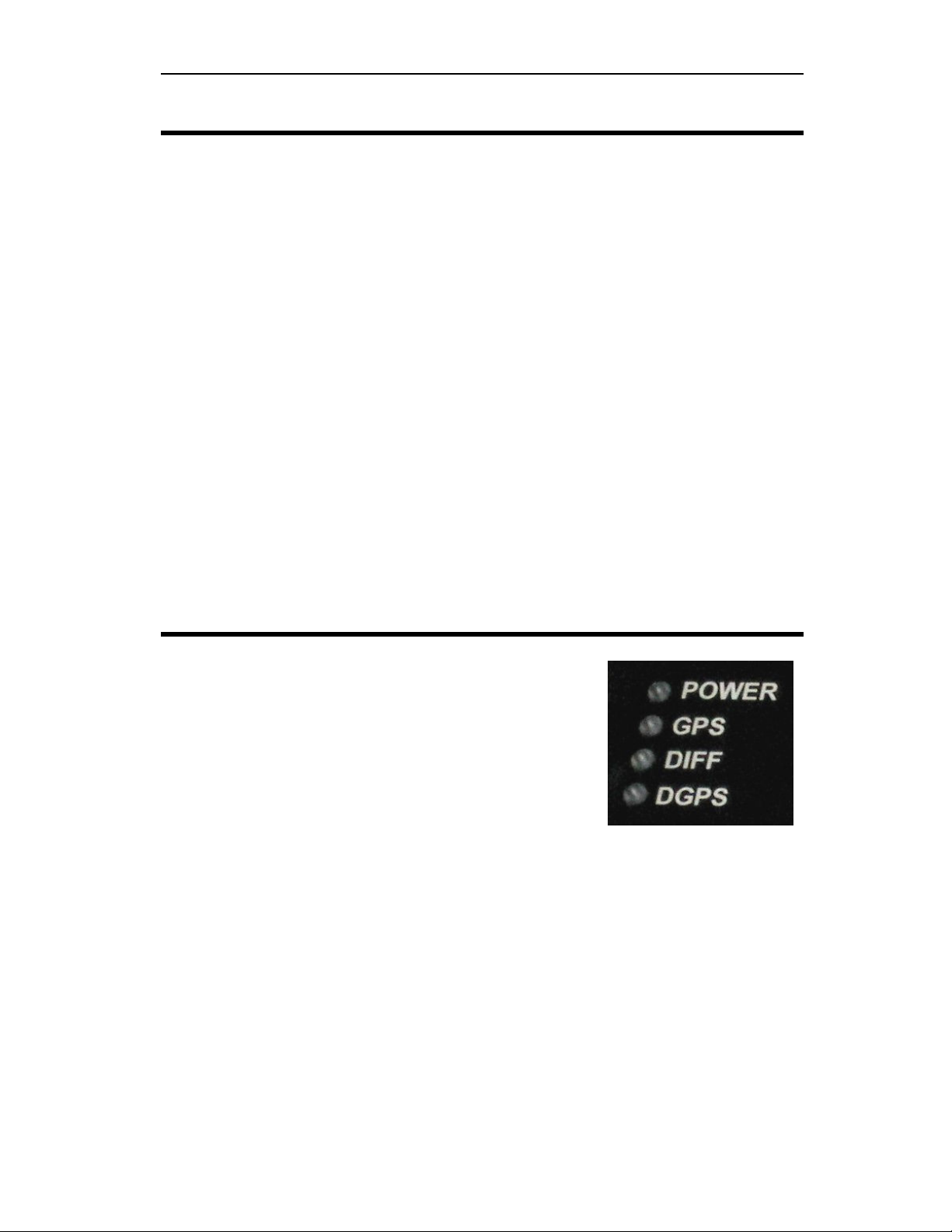
Status LEDs
There are 4 LEDs on the front face of the unit
labeled as follows:
• P WER (red): Unit has power.
• GPS (yellow): GPS signals have been
acquired and calculated data is being
sent out.
• DIFF (yellow): SBAS differential satellite available.
• DGPS (green): Differential corrections are active, resulting in
improved data. This is the light you really want to see on.
There are only two required lights for operation, one is P WER and the
other GPS. The DIFF and DGPS lights indicate increased accuracy of
the data. With differential correction, you will get the most accurate
data. Therefore best operation is achieved with these lights on.

RaceGrade
GPS
Page
5
RS-232 Serial Output
Standard NMEA-0183 message strings GPGGA and GPRMC are
sent out by default at a baud rate of 57,600. The baud rate and type of
messages can be changed by sending the unit back to RaceGrade.
CAN Output
The RaceGrade GPS version 2 receive now includes a CAN
output. The CAN bus speed operates at 1 mbit/s and on the base ID of
0x146. The CAN output is based off the MoTeC GPS with STC (serial
to CAN). Simply select the “GPS Async” template for MoTeC devices.
20 Hz Update *Option
This option allows the following four channels to update at a true
20 Hz rate:
• GPS Latitude
• GPS Longitude
• GPS Speed
• GPS Heading
It’s best to buy this option at the time of purchase. If you buy it
afterwards, the unit must be sent to RaceGrade for updating.
* Options must be specified at the time of ordering

RaceGrade
Notes 6
Installation
GPS Receiver
The enclosure is made from 6061 Aluminum alloy. It should be
mounted in a safe location, away from electrical noise, vibration and
temperature. Maximum operating temperature is 70°C or 158°F.
NO E: To counter any possible vibration da age, please ount
the receiver box on soft Velcro, not the hard industrial type or
even double sided foa tape.
Antenna
The location of the antenna is VERY important. It should be
mounted such that it can have a clear view of the sky out to 5 degrees
above the horizon. Poor mounting locations will have a large negative
impact on the results from its calculated data.
Normally the best location would be on top of the race car. For
motorcycles, on top of the rear fairing works well. n a closed-wheel
race car the best choice is the roof. For best performance, do not place
the antenna under the front or rear window. For open-wheeled cars, on
top of the roll hoop, or just in front of the cockpit works best.
It’s best to have the correct length specified when ordering.
• GPS signals are easily blocked by electrical noise. Keep the
antenna more than 6” from any other antennas such as car-to-
pit voice radios, telemetry and other GPS antennas.
• For cars with “live TV coverage cameras”, most of them send
their signal at the same frequency as GPS. Therefore you
must separate the GPS antenna and wire to the opposite side
of the car. Keep the TV antenna and wire as far away as
possible from the GPS antenna and wire.
• Keep the antenna outside any of any metal or carbon fiber
enclosed space, as these materials will block satellite signals.
Plastic, duct tape as well as fabric convertible tops are
generally ok.
• The antenna should be kept flat or parallel to the ground. If
mounted on a slope then the ability to receive signals will
RaceGrade
Notes 7
decrease slightly. Keep this in mind when mounting on a
motorcycle as the bike leans from corner to corner.
• Try to keep the antenna mounted on the centerline of the
vehicle. As with normal wheel speeds, during cornering the
speed of the inner side of the chassis is less than the speed of
the outer side of the chassis.
• The antenna has a magnet base to hold itself onto a metal
surface. If you use double sided tape or hook & loop, when
removing please be careful not to remove the bottom silver
sticker from the antenna. This sticker has a metal film that help
reject false signals and shield it from noise.
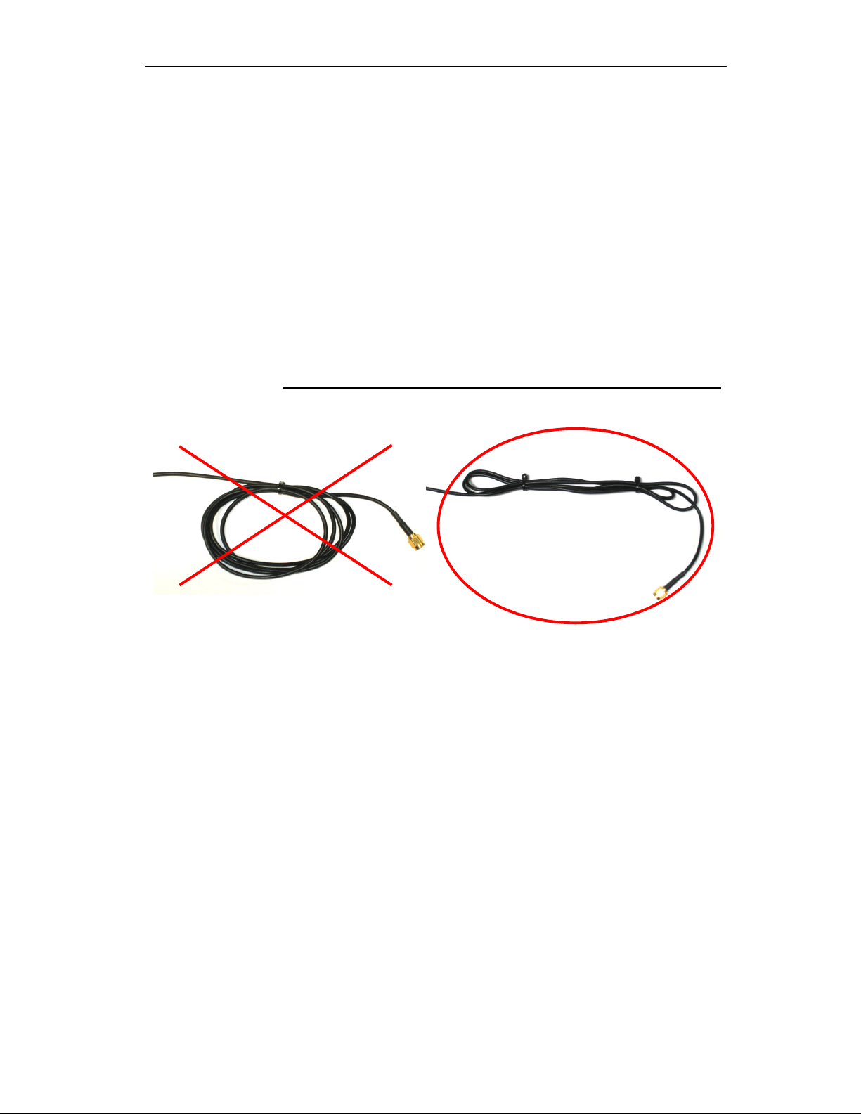
• Any extra antenna wire can be zip tied in a back and forth
bundle. Do not coil the extra antenna wire length in a circle
or wrap it around anything. Simply run the extra antenna wire
back and forth.
Loss of Signal
As mentioned earlier, the antenna must see as many satellites as
possible. The antenna should have a clear view of the sky, ideally a
clear line of sight to the sky down to 5 degrees above the horizon. If
part of the sky is blocked by a building, tree or bridge then the GPS unit
will loose track of those satellites being blocked. When this happens, a
reacquisition will take place which can take some length of time. Loss
of signal can occur when driving under bridges. The size of the bridge
and satellite location (time of day) has an impact on the acquisition of
satellites. You should always log your satellite count to be aware of
what the antenna saw while traveling around the race track.

RaceGrade
Notes 8
GPS Quality
The channel “GPS Sats Used” is a value that represents the number of
satellites used in the calculations. A value of 8 to 10 is excellent. A
value of 6 or 7 is decent but may suffer some noise. Values below 6 will
have very poor accuracy.
For the RaceGrade GPS, the number of satellites does not include the
SBAS or WAAS DGPS satellites. So a value of 10 is the maximum
possible even though the unit is capable of tracking 12 satellites. Most
other GPS units include these in the reported satellites used. Most other
GPS units accept multi-path signal and therefore the channel “GPS
Sats Used” can not be analyzed to estimate accuracy with any degree
of precision.
Setup for SDL, ADL2, ADL3, ACL
For ADL2, SDL or ACL use, please select the template “GPS -
Standard RMC GGA” listed under the communications RS-232. Verify
57,600 for the baud rate. You’ll be able to log the following channels of
information:
Recommended Logging Rates
Update Option: 10 Hz 20 Hz
• GPS Latitude 20 Hz 50 Hz
• GPS Longitude 20 Hz 50 Hz
• GPS Speed 20 Hz 50 Hz
• GPS Heading 20 Hz 50 Hz
• GPS Date 1 Hz 1 Hz
• GPS Time 10 Hz 10 Hz
• GPS Sats Used** 10 Hz 10 Hz
• GPS Altitude 10 Hz 10 Hz
For the 10 Hz update rate, channels should be logged at 20 Hz even
though they only update at 10 Hz. This will help minimize the time delay
between when the data arrives to the logging device through the serial
stream and the moment the values are logged. For the 20 Hz option,
those channels which update at 20 Hz should be logged at 50 Hz. GPS
Date should only be logged at 1 Hz. See the table above.

RaceGrade
Notes 9
“i2” Analysis Math
GPS data will have an inherent time lag. The sequence of delays
are from receiving real-time satellite signals, processing them, sending
the data into the logger and the logger logging them. MoTeC’s “i2” has
a built-in “Corrected GPS” function found under the “Tools” pull down
menu. This function should only be used with data originating from a
ADL2, SDL or ACL.
Actual shift may vary. You can use either the Auto function or
manually adjust the time delay. The 10 Hz unit typically has a delay of
approximately 130 msec. The 20 Hz unit typically has a delay of
approximately 110 msec.
Table of contents


