Raptor Photonics Ninox 1280 User manual

1
NINOX 1280
Model: NX1.7-VS-CL-1280
USER MANUAL

2
CONTENTS
1. INTRODUCTION ................................................................................................................................................................... 3
1.1 Scope.......................................................................................................................................................................... 3
2. CAMERA CARE ..................................................................................................................................................................... 3
2.1 Cleaning the Sensor Window.................................................................................................................................... 3
3. SPECIFICATION..................................................................................................................................................................... 4
3.1 Camera Specification................................................................................................................................................. 4
3.2 Specification Table .................................................................................................................................................... 4
4. MECHANICAL DESIGN ......................................................................................................................................................... 5
4.1 Mechanical Model................................................................................................................................................ 5
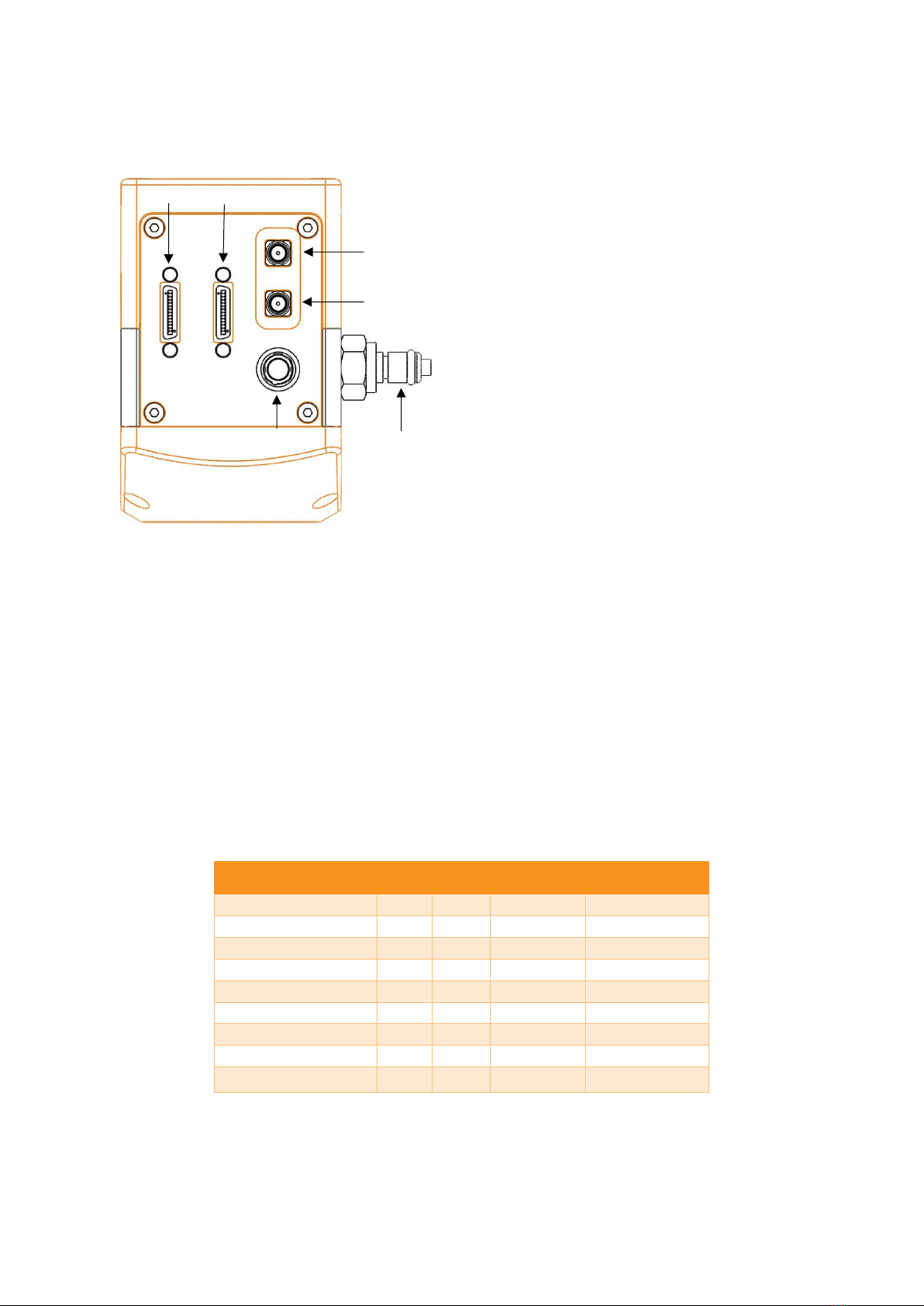
4.2 Physical Interface ................................................................................................................................................. 6
4.3 Mounting to Microscope ..................................................................................................................................... 6
4.4 Mounting to a tripod or optical table ................................................................................................................. 6
5. SOFTWARE COMPATIBILITY ................................................................................................................................................ 6
5.1 Compatibility Table .............................................................................................................................................. 6
5.2 XCAP Compatibility............................................................................................................................................... 7
5.3 Micromanager Compatibility............................................................................................................................... 7
5.4 LabView Compatibility ....................................................................................................................................... 7
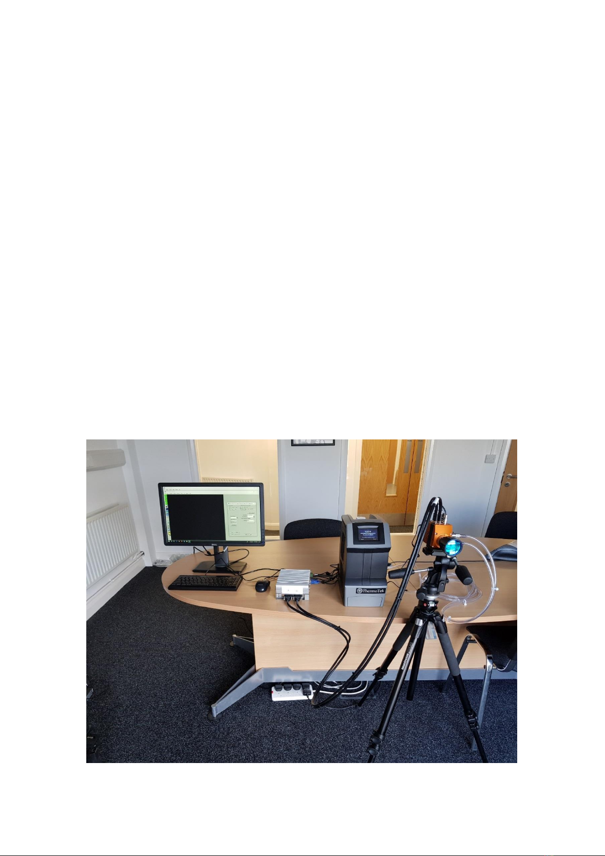
6. CAMERA SETUP.................................................................................................................................................................... 7
6.1 Connecting Camera to Chiller.............................................................................................................................. 8
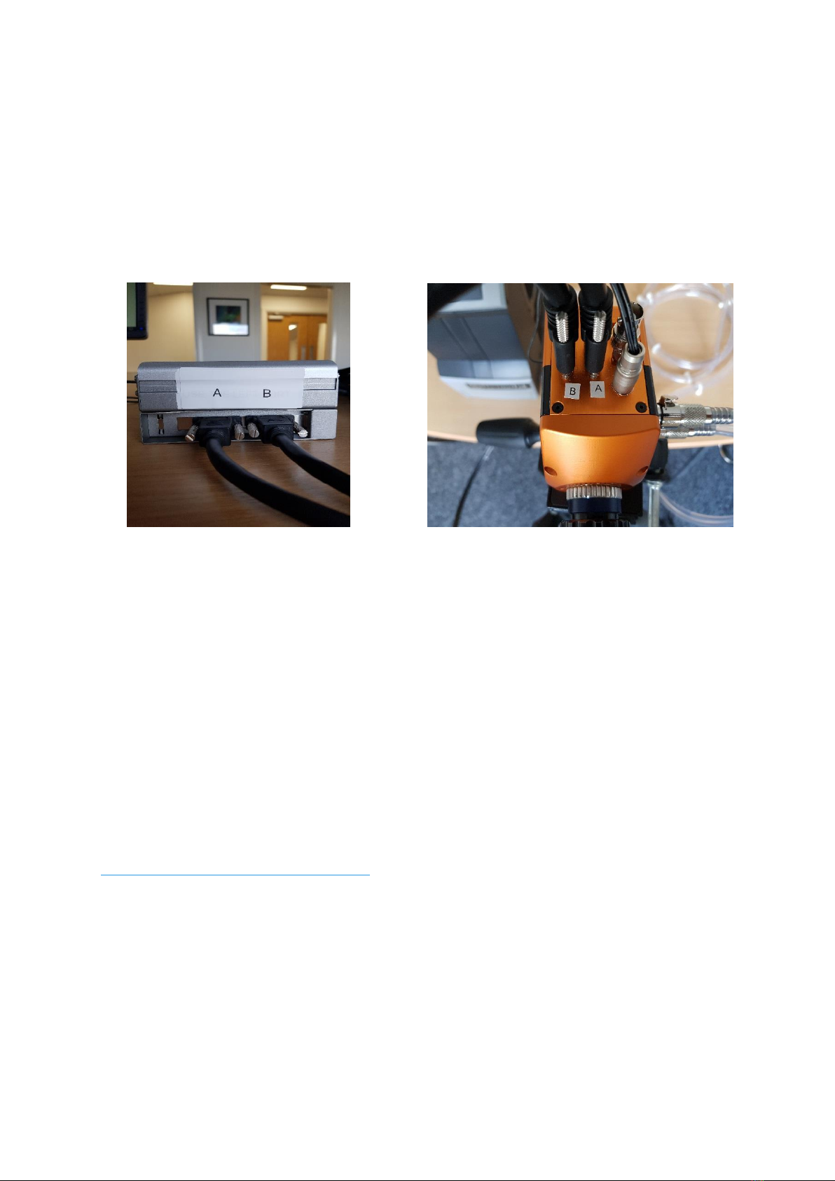
6.2 Connecting Camera to Frame Grabber............................................................................................................... 8
7. XCAP IMAGING SOFTWARE................................................................................................................................................. 9
7.1 Computer System Requirements. ....................................................................................................................... 9
7.2 Frame Grabber Requirements............................................................................................................................. 9
7.3 Downloading and Installing XCAP........................................................................................................................ 9
7.4 Opening Camera Configuration......................................................................................................................... 10
7.5 Ensuring the Camera is Connected ................................................................................................................... 11
7.6 Acquiring a Live Image Sequence...................................................................................................................... 12
7.7 Controlling the Camera...................................................................................................................................... 12
7.7.1 Gain, Exposure & Frame Period. .................................................................................................................. 12
7.7.2 Triggering Modes. ......................................................................................................................................... 14
7.7.3 Thermoelectric Cooler (TEC). ....................................................................................................................... 14
7.7.4 Non-Uniformity Correction (NUC)................................................................................................................ 15
7.7.5 Auto Exposure Control (ALC):....................................................................................................................... 16
7.7.6 Auto Exposure ROI Control........................................................................................................................... 17
7.7.7 Miscellaneous Section. ................................................................................................................................. 19
7.7.8 Manufactures Data Information .................................................................................................................. 19
7.7.9 Saving Preset Settings................................................................................................................................... 20
7.7.10 Contrast Modification................................................................................................................................... 21

3
1. INTRODUCTION
1.1 Scope
This manual covers the Ninox 1280 digital camera and all applicable components. Raptor recommends
that this manual be used to optimize camera operation.
2. CAMERA CARE
2.1 Cleaning the Sensor Window
Raptor cameras require no regular maintenance except occasional external cleaning of the sensor
window (the glass window between the camera sensor and the microscope or lens). Use optical grade
isopropyl to clean this window. A cotton swab can be used, but may leave some fibres on the window,
so be careful. To avoid this, you could also use a lens tissue or a cleaning swap such as a texwipe.
Forced air can be applied to remove any loose particles. Should any other issues occur please contact
your local agent.
CAUTION —The camera’s sensor and circuits are sensitive to static discharge. Ensure that you are
using a static strap or completely grounded at all times to release any static energy before you clean
the window.
CAUTION —Do not use acetone.

4
3. SPECIFICATION
3.1 Camera Specification
The Ninox 1280 VIS-SWIR is designed for high resolution applications requiring visible to SWIR imaging
(400-1700nm). The camera uses an InGaAS sensor with a resolution of 1280 x 1024. High-speed low-
noise electronics provide linear response and sensitivity for rapid image capture.
The Camera Link digital interface provides the most stable platform for data transfer and the camera
will work on any Camera Link standard card.
Raptor works closely with EPIX, whos frame grabbers we offer with our cameras. If, using their frame
grabbers, we offer their Software Development Kit (SDK) for interfacing with custom software. If using
another companies frame grabber of your choosing, then you will have to obtain their SDK.
3.2 Specification Table
SPECIFICATION
Sensor Type
InGaAs PIN-Photodiode
Active Pixel
1280 x 1024
Pixel Pitch
10μm x 10μm
Active Area
12.8mm x 10.24mm
Spectral response1
0.4μm to 1.7μm
Readout Noise (RMS)
LG = Low Gain HG = High Gain
LG: <190 electrons (160 electrons typical)
HG: <50 electrons (47 electrons typical)
Quantum Efficiency
>80% @ 1.55μm
Full Well Capacity
LG: 450ke-
HG: 10ke-
Pixel Operability
>99%
Digital Output Format
12 bit Camera Link (Medium Configuration)
Dark Current (e/p/s)
<4,000 @ 15°C (2,000 typical)
Exposure time2
LG = Low Gain HG = High Gain
LG: 300μs to 10s
HG: 600μs to 86.5ms
Frame Rate3
10 to 60Hz
Dynamic Range
LG: 69dB, HG: 47dB
Optical Interface
C-mount (selection of SWIR lenses available)
Trigger interface
Trigger IN and OUT –TLL compatible
Power supply
12V DC ± 0.5V
TE Cooling
Cooled to -15 C (∆T = 35 C)
Non-Uniformity Correction
(NUC)
3-point NUC (offset, gain & dark current) +
pixel correction
Functions Controlled by Serial
Communication
Exposure, Intelligent AGC, NUC , Gamma,
Pk/Av, ROI
Camera Power Consumption4
<3W with TEC OFF, NUC ON
<5W with TEC ON, NUC ON
Operating Case Temperature5
-20°C to +55°C
Storage Temperature
-30°C to +60°C
Dimensions (L*W*H)6
87.30mm x 78.86mm x 79.30mm
Weight
550g

5
Note 1: Optional filters available: Low, High or bandpass.
Note 2: For exposure times up to 10s, the camera will have to be switched to long exposure mode.
This mode only operates in low gain and there is no NUC. When in normal mode and in low gain, the
maximum exposure time is 90ms with an active NUC. In high gain in normal mode, the NUC is also
active for the full exposure time range up to the maximum 80ms exposure.
Note 3: Frame rates lower than 10Hz are achievable when in the long exposure mode discussed in
note 2.
Note 4: Measured in an ambient of 25˚C with adequate heat sinking.
Note 5: Extended Operating Temperature range on request.
Note 6: Dimensions include all connector parts on camera.
4. MECHANICAL DESIGN
4.1 Mechanical Model
PDF of mechanical model available from our website.

6
4.2 Physical Interface
4.3 Mounting to Microscope
The Ninox 1280 has a standard C-Mount that should easily screw onto any microscope port.
4.4 Mounting to a tripod or optical table
The camera has a ¼-20 BSW (Whitworth), threaded hole to mount to a tripod or an optical table.
5. SOFTWARE COMPATIBILITY
5.1 Compatibility Table
XCAP
XCLIB
NI Labview
Micromanager
Hawk 252
Falcon III
Eagle
Owl 320 High Speed
Owl 'Mini'
Owl 640
Ninox 640
Owl 1280
NINOX 1280
2
3
4
5
1
6
1. 4 Pin Hirose Connector
2. SDR Camera Link Connector
3. SDR Camera Link Connector
4. SMA Connector: Trigger OUT
Single ended, source impedance =
51Ω, capable of sinking and
sourcing 32mA and will have an
output voltage of 3.3V i.e. TTL
compatible.
5. SMA Connector: Trigger IN
Single ended, termination
impedance = 510Ω, capacitive load
= 200pF [TTL compatible].
6. Liquid cooling IN/OUT valve
coupling (x2 IN/OUT)
- Software tested by Raptor Photonics
- Software tested by other companies
Blank - The camera has not been tested or is not supported by this software

7
5.2 XCAP Compatibility
Raptor works closely with EPIX who integrate all of the Raptor camera models into their XCAP
Imaging Software package. XCAP is the core plug and play software package that is offered with
Raptor cameras.
5.3 Micromanager Compatibility
There is a selection of Raptor cameras integrated into the free open source imaging software
Micromanager. The cameras currently supported can be seen in the table outlined in section 5.1.
5.4 LabView Compatibility
Raptor can provide LabView Interface Control Document files (.icd) to image and control the camera
on National Instruments Software such as NI MAX. Contact a Raptor Sales employee to obtain this
file.
6. CAMERA SETUP
This section will talk through setting up the camera, including connecting to the frame grabber and
chiller (if applicable). Below is an image of a normal setup of the camera, computer and chiller. For
most applications, the chiller may not be necessary to use with the Ninox 1280, as the fan is
normally adequate at dissipating heat from the device. If imaging the camera in a high ambient
temperature environment, water cooling may be required to keep the PCB temperature low enough
in order to hit the optimum -15 C TEC set point. The maximum delta between the PCB and sensor
temperature is discussed in section 7.7.3.

8
6.1 Connecting Camera to Chiller
If using a chiller, the water tubing simply needs connected from the camera water connectors to the
chiller connecters, as shown in the image below. You will hear a click which indicates a solid
connection. The polarity of the tubing connections does not matter.
Please consult the Ninox 1280 data sheet for a list of recommended re-circulators and tubing
accessories required. The set-up is as follows:
•Connect the cooling pipes and tubes to the from the Chiller to the camera.
•Fill the chiller with the liquid, filling to the bottom of the neck.
•Switch on the circulator; you will now see bubbles traveling along the tubing.
•Wait for the bubbles to bleed into the reservoir, top up the reservoir as required. You should tilt
the camera side to side to ensure there are no bubbles remaining in the camera.
•Click “Start” to begin circulating water.
•Now set the Temperature set point on the circulator. For the Ninox 1280 camera, 20°C is
preferred.
WARNING: Please ensure the temperature set point of the re-circulator is above your ambient dew
point, otherwise condensation can form around the sensor package and cause damage.
Disassembly and draining:
•Disconnect all the tubing from the camera and re-circulator.
•The camera and tubes should be drained by holding the adaptor with the tubing above the
camera.

9
6.2 Connecting Camera to Frame Grabber
All demo cameras and PC units should be marked with an A and B symbol, which indicates the
polarity required for connecting the two frame grabber ports to the Camera Link MDR ports on the
camera head. This is shown in the two pictures below. Another way to distinguish which ports
connect together, is that the MDR port closest to the power connector on the camera head needs to
be connected to the frame grabber port nearest to the PCIe slot.
7. XCAP IMAGING SOFTWARE
7.1 Computer System Requirements
Contact EPIX Inc. for the latest information regarding minimum computer specification requirements
to run the XCAP Imaging Software.
7.2 Frame Grabber Requirements
With the Ninox 1280, it is a minimum requirement to use an PIXCI E8 frame grabber. If using a frame
grabber from another company, the spec requirements of this frame grabber must meet those
supplied by the PIXCI E8 model.
7.3 Downloading and Installing XCAP
The latest version of XCAP can be downloaded from the link below:
http://www.epixinc.com/support/files.php
please select the appropriate version of XCAP for your computer. Ensure that you download from the
section labelled “Pre-release version with support for the latest cameras and latest PIXCI® imaging
boards”.Open the downloaded file when complete and follow the onscreen instructions in the
installation wizard. If a pop-up message appears asking whether to install the PIXCI driver, ensure that
you click yes.

10
7.4 Opening Camera Configuration
After opening XCAP, select “PIXCI Open/Close” from the “PIXCI” tab from the top menu bar in the
main window. A PIXCI Open/Close pop-up box will open as shown in Figure 1 below:
Click on “Camera & Format” that is highlighted in Figure 1 and a “PIXCI Open Camera & Format” box
will appear, as shown in Figure 2 below:
Figure 1: PIXCI Open/Close.
Figure 2: PIXCI Open Camera & Format.

11
Using the dropdown menu highlighted, search for “Raptor Photonics Ninox 1280”. Alternatively, you
can use the search button and typing Ninox 1280 will bring you to the correct file. Selecting “Open w.
Default Video Setup” will open the control panel with all control parameters set to the default states.
“Open w. Last used Video Setup” will open the control panel with all parameters set at the last
known state. Once this option between the two has been selected, click “Ok”. To open the camera
control panel and imaging window, click “Open” in the “PIXCI Open/Close” window (Figure 1).
Two windows will now open in XCAP, and imaging window and control panel, as shown in Figure 3
below:
7.5 Ensuring the Camera is Connected
There are two things to observe in the control panel that inform you that the camera is connected
and ready to image.
The serial connect checkbox must be ticked in the control panel. This informs you that you have
established a serial connection with the camera and can control the camera.
Secondly, the symbol near the bottom right of the control panel will have three moving dots. This
means that you are obtaining video data from the camera.
Both symbols are highlighted in Figure 4 below:
Figure 3: Imaging Window & Control Panel.

12
7.6 Acquiring a Live Image Sequence
Once you have established a serial connection with the camera and are receiving video data, you can
now grab a live image feed. Clicking the “Live” button, also highlighted in Figure 4, will grab a live
image sequence which you will now see in the imaging window.
Live imaging statistics are shown below the imaging window (resolution & frame rate), highlighted in
Figure 3.
7.7 Controlling the Camera
The XCAP control panel provides full control over the camera. The below sections will go through
each control tab, giving a description on how to use them on XCAP and their effect on the camera’s
performance.
7.7.1 Gain, Exposure & Frame Period
The gain, exposure time and frame period can be controlled from the “Gain” tab. By default, the
auto exposure is enabled, which will automatically control the exposure time and digital gain.
Toggling the “Auto Level Control” box will disable the auto exposure control and the user will now
be able to manually adjust these settings. The user can manually change the gain setting of the
camera between high and low gain. High gain has a smaller pixel full well capacity but offers lower
noise. The camera will be set in low gain by default. If imaging a very weak signal or for night-time
imaging, high gain would be more optimal. These controls are illustrated in Figure 5 below.
Figure 4: Port Tab –Checking Camera Connection.

13
Exposure times can be selected that are possible under the current frame period selected. The
default frame period is 40ms (25Hz). From Figure 6 below, you can see that for this frame period,
XCAP enables the user to select exposure times in the range of 0-32ms in low gain and 0-26.5ms in
high gain.
This is due to the readout time in both gain modes. The relationship between the frame period,
exposure time and readout time is stated below, which applies for all frame periods set:
Frame period = Exposure Time - Readout Time
Therefore, the maximum possible exposure time with a 40ms frame period is:
LOW GAIN: Max. Exposure Time = 40ms - 7.5ms (readout time in low gain)
= 32.5ms
HIGH GAIN: Max. Exposure Time = 40ms - 13.5ms (readout time in high gain)
= 26.5ms
Figure 5: Gain, Exposure and Frame Period Controls.
Figure 6: Frame Period and Exposure Time Controls (Low Gain left, High Gain right).
Toggle the auto exposure
control on and off.
Adjust the frame period
from 16.7ms to 100ms (10-
60Hz frame rate
specification).
If the ALC is disabled, the
user can manually set a
fixed exposure time.
Set the gain mode (high or
low gain).
If the ALC is disabled, the
user can manually set a
fixed digital gain.

14
Minimum and Maximum Exposure Times:
The minimum and maximum exposure times in both gain modes are stated in the table below for
the Ninox 1280:
Low Gain
High Gain
Minimum Exposure1
20µs
40µs
Maximum Exposure2
92.498ms
86.46ms
1Subjective to customers application. Image scene needs sufficient illumination to achieve pixel well fill above the camera noise floor.
What is defined as a useable image will also vary between applications.
2The maximum exposure of 10s in low gain mode stated on the datasheet is not yet officially released or implemented into XCAP.
7.7.2 Triggering Modes
The cameras triggering mode can be toggled from the “Trigger” tab, shown in Figure 7. By default, the
camera will be using the internal trigger, which is the “Live” option in the “Readout Mode” dropdown
bar. This can be changed to external trigger if wanting to externally trigger the camera.
Enabling the external trigger will open the trigger polarity and trigger delay options. You can choose
rising or falling edge trigger polarities, as well as set trigger delays.
There is also a frame rate dropdown menu in this tab which gives discrete frame rate options (25Hz,
30Hz, 50Hz and 60Hz).
Figure 7: Trigger Tab.
Select the readout mode
(internal or external
trigger).
Discrete Frame Rate
Options can be selected.

15
7.7.3 Thermoelectric Cooler (TEC)
The “TEC” tab in the GUI gives the user control over the TEC and fan. The minimum and optimum
cooling temperature is -15 C. This is what the TEC set point will be by default, as highlighted in Figure
8. The fan will also be enabled by default, as the fan is required for the TEC to be able to hit -15 C.
The sensor can also be read from this tab.
There is roughly a 35 C delta between the sensor and PCB temperature. Therefore, to be able to
maintain the -15 C set point, the PCB temperature will have to remain around room temperature.
The PCB temperature can be read in the “Misc” tab which is discussed in section 7.7.6.
7.7.4 Non-Uniformity Correction (NUC)
The “NUC” tab gives the user control over the NUC that is performed live on-board the FPGA chip in
the camera. The Ninox 1280 offers a 3-point NUC (offset, gain & dark current) and a bad pixel
correction. XCAP gives the option to apply each state of the NUC. In practice, the user will want to
have either the NUC completely disabled (Normal) to receive the raw data from the sensor, or the 3-
point NUC enabled (Offset+Gain+Dark) & bad pixel corrections.
The ramp test pattern image can also be enabled from this tab, which will consist of a fixed ramp
pattern that will start with a value of 0 on the first pixel read from the camera and increment by one
for each subsequent pixel read from the camera.
These controls can be seen from Figure 9.
Figure 8: TEC Tab.
Controls to turn the TEC
and fan ON/OFF. The
desired TEC set point can
also be set if the TEC is
enabled.
The sensor temperature
can be read using the
“Update Temp.” button.

16
7.7.5 Auto Exposure Control (ALC)
The “Auto” tab gives control over the ALC. Adjusting the parameters shown in Figure 11 will fine
tune the ALC to the users liking, which will depend on factors just as signal strength, the users
application etc. A description of what these control parameters do is stated below:
ALC from Peak & ALC from Mean:
Peak video is determined from a rolling average of 4 pixels. Current pixel + 3 previous pixels are used
to derive the peak value. This peak value is monitored for the ROI (Region of Interest) and latched at
the end of frame.
An average video level is calculated for the active ROI. This value will be calculated in real time, i.e.
as pixel data in the ROI is captured from the sensor it is fed directly to an Accumulator. At the end of
frame, the Accumulator is divided to give a true average.
The user can adjust the percentage they want to take from the peak & average to drive the ALC.
Taking a greater percentage from the peak value will result in smaller exposure times being set.
Taking a greater percentage of the average to drive the ALC will result in larger exposure times being
set.
ALC Level & AGC+ALC Speed: Adjusts the “level” of the ALC. Making the level and speed set points
higher will drive the ALC to set larger exposure times.
Figure 9: NUC Tab.
By default, the state of the
NUC that should be used is
the full 3-point NUC
(Offset+Gain+Dark
corrections). User has the
option to view each state
of the NUC or the raw data
from the sensor with no
corrections applied
(Normal).
Ramp test pattern can also
be enabled.

17
7.7.6 Auto Exposure ROI Control
The pixel values used in the accumulator that drives the ALC can be selected from the “Auto ROI”
tab. By default, the whole pixel array will be selected for this (1280x1024) as shown in Figure 11.
Figure 10: ALC Tuning.
Figure 11: Auto ROI.
All controls to tune the
ALC to fit the user’s
application
requirements.
All controls to select the
pixel region that will
drive the ALC.

18
The ROI can be made smaller and moved around the image array by adjusting the width and height
and offset controls. Selecting “ROI Box” from the “ROI Highlight” drop down box will outline the ROI
on the imaging window that is currently set.
An example of this feature in action is shown in Figures 12–13. The images were taken using our
Owl 640 camera, but the exact same principle applies for the Ninox 1280, as both cameras have
these identical control feature.
In Figure 12, you can see that the ROI is 146x146 and is active over the carpet of the floor, which is
setting a good exposure time for the carpet region. However, the suitcase is very dark and under
exposed.
If the ROI is moved to an area on the suitcase, the pixels in this region will now drive the ALC. This
can be seen in Figure 13.
You can see from Figure 13 that the exposure value being set by the ALC is larger due to lower pixel
values driving the ALC. The suitcase is now better exposed. However, the exposure is still always
changed for the whole image array, saturating the rest of the image.
Figure 12: Auto ROI Example.
Figure 13: Auto ROI Example.

19
7.7.7 Miscellaneous Section
The “Misc” tab highlights the bad pixels that the NUC is correcting for, seen in Figure 14.
7.7.8 Manufactures Data Information
The “Info” tab displays information about the camera such as the manufactures data:
FPGA & Micro Version: The current firmware version of the camera is displayed.
Serial #: States the serial number of the camera.
Build Date & Code: Gives the date that the camera was built.
ADC & DAC Calibration Values: These are calibration values that are used to set the TEC set point
and read back the sensor and PCB temperatures. They are not needed for the user as the XCAP GUI
has simple buttons to set and read back these temperatures, discussed in earlier sections.
CCD & PCB Temperature: The current sensor and PCB temperature of the device can be read by
clicking “Update Temp”.
Figure 14: Miscellaneous Tab.
Selecting “Highlight”
from this dropdown box
will show the bad pixel
map that the camera is
correcting.

20
7.7.9 Saving Preset Settings
Different camera and frame grabber settings can be saved in the “Preset” tab under the PIXCI E8
section of the GUI, shown in Figure 16.
Up to three different presets can be saved per settings file. Once the camera is set to the desired
state, click “Save 1”. This can be done a further two times. These camera states can be recalled at
any time by using the recall buttons. The overall settings file can then be saved and loaded in this tab
also. Three preset states is the maximum number that can be saved in a settings file.
Figure 15: Manufactures Data Information.
Figure 16: Presets.
Manufactures data
displayed in this tab. The
sensor and PCB
temperature can also be
read.
Three different preset
states can be saved in
the following tab, with
each of them being able
to be recalled at any
time.
The states stored can be
then saved as a settings
file.
This manual suits for next models
1
Table of contents