rauland MCX300 Owner's manual

Installation and Operation KI-1976
MCX300 AM-FM Tuner and
Cassette Tape Player
Rauland-Borg Corporation
Issued: 07/01/98
Page 1 of 8

Copyright 1998 by Rauland-Borg Corporation, all rights reserved.
This document contains user’s information on technology that is proprietary to Rauland-Borg
Corporation. Permitted transmittal, receipt, or possession of this document does not express license or
imply any rights to use, sell, design or manufacture this information. No reproduction, publication, or
disclosure of this information, in whole or in part, shall be made without prior written authorization from
an officer of Rauland-Borg Corporation.
©Rauland-Borg Corporation
Rauland-Borg Corporation
3450 West Oakton Street
Skokie, Illinois 60076-2958
(847) 679-0900
www.rauland.com

MCX300 AM-FM Tuner and Cassette Tape Player
—Installation and Operation
Page 3 of 8 (Jul-98)
Table of Contents
GENERAL INFORMATION.............................................................................................................................................. 4
'
(6&5,37,21
..................................................................................................................................................................... 4
Revised Model............................................................................................................................................................... 4
DRAWINGS, DIAGRAMS, AND OTHER GRAPHICS .................................................................................................................. 4
3
$&.,1*
/
,67 $1'
8
13$&.,1*
3
52&(66
........................................................................................................................... 5
5
(48,5('
$
17(11$
.......................................................................................................................................................... 5
AUDIO OUTPUT .................................................................................................................................................................. 6
Power........................................................................................................................................................................... 6
6
(77,1* 7+(
&
21752/6
.................................................................................................................................................... 6
2
87'225
$
17(11$6
........................................................................................................................................................ 7
OPERATING INSTRUCTIONS................................................................................................................................................. 7
The Monitor-Program Switch........................................................................................................................................ 7

MCX300 AM-FM Tuner and Cassette Tape Player
—Installation and Operation
Page 4 of 8 (Jul-98)
General Information
'HVFULSWLRQ
The Rauland MCX300 AM-FM Tuner and Cassette Tape Player comes ready to be
rack-mounted. It includes a separate 12-VDC power supply that can be plugged
into any convenient 120-VAC power outlet. There is a standard female “F”
connector to accommodate a coaxial cable from the external antenna required for
the AM-FM tuner, and an RCA-type phono jack for connecting the unit’s
unbalanced monaural audio output to a sound or communications system. The
audio output provides ample signal for the auxiliary input of an amplifier or a
communications system.
Revised Model
This manual is for the revised MCX300, which began shipping in May 1996. It
features a slightly different tuner and tape player but retains the same specifications
and convenient plug-in connectors as the previous model. For the older-versions of
the MCX300, see KI-1745, KI-1967, KI-1950 and KI-1972.
Drawings, Diagrams, and Other Graphics
This document includes the following drawings, diagrams, and/or supplemental
graphics:
9
Installation Example (IL0153)
9
Wiring Diagram (KM0710)
1

MCX300 AM-FM Tuner and Cassette Tape Player
—Installation and Operation
Page 5 of 8 (Jul-98)
3DFNLQJ/LVWDQG8QSDFNLQJ3URFHVV
The MCX300 comes completely assembled. The only separate items besides the
main chassis are the AM/FM cassette receiver manual, the 12-VDC power supply
and the screws, washers, & self-retaining nuts for fastening the chassis to the rack:
Supplied Parts
Quantity Part Part Number
1 12-VDC power supply. PS12
4 Black #10 flat washers. WJ0305
4 Fiber washers. WL0315
4 #10-32 self-retaining nut fastener. AB3640
4Black machine screws (#10-32 ×5/8" pan-head
Phillips). B0439
1Manufacturer’s AM/FM Cassette Radio
Manual none
Parts to be Supplied by the Installer
Quantity Part
1 FM antenna with mast and supporting hardware.
1 AM antenna wire with mast and hardware.
1 AM/FM antenna coupler and protective housing.
1 75 W shielded coaxial cable from the antennas to the tuner.
1 Lightning-protection system.
1Shielded cable to connect the MCX300 to a sound or communications
system. One end should have an RCA-type phono plug; the other, a
suitable connector for the sound or communication system’s Auxiliary
or Tuner input.
Equipment Damaged in Transit: This equipment was carefully inspected and
tested at the factory before it was shipped. If it has been damaged in transit, notify
the transportation company immediately to place your claim.
5HTXLUHG$QWHQQD
An external 75-ohm antenna is required for the AM-FM tuner. The type of antenna
to use depends upon the equipment’s location within the building and the strength

MCX300 AM-FM Tuner and Cassette Tape Player
—Installation and Operation
Page 6 of 8 (Jul-98)
of the radio signals in the area. For most installations, Rauland recommends the
antenna system shown in the attached wiring diagram, KM0710.
Important:
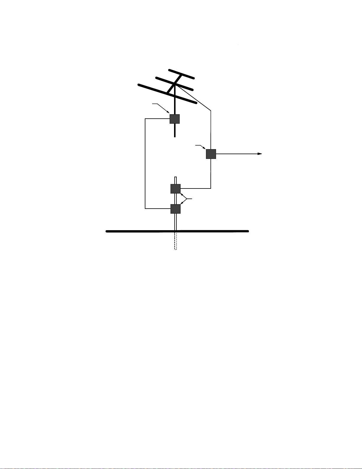
The system should be installed with some protection against lightning. Articles
810 and 820 of the National Electrical code, ANSI/NFPA No. 70-1978, provide
detailed information regarding the grounding of (a) the mast and the supporting
structure, (b) the lead-in wire to an antenna discharge unit, and (c) the coaxial
cable system. The Code also specifies the size of the grounding conductors, the
locations of the antenna discharge units, the connections to the grounding
electrode, and the requirements for the grounding electrode. An example of an
installation meeting these requirements is given in the attached illustration,
IL0153.
Audio Output
Obtain a single-conductor shielded cable of suitable length to connect the Audio
Output jack on the back of the chassis to the Auxiliary or Tuner input of the sound
or communications system. Terminate one end of the cable in a male RCA-type
phono plug; the other end should have a connector that matches the input of the
system.
Plug the RCA-type phono plug into the “Audio Output” jack of the MCX300, and
the other end of the cable into the “Auxiliary” or “Tuner” input of the main system.
Power
Insert the output plug of the power supply into the “Power Input” jack on the back
of the MCX300, then plug the power supply itself into a suitable 120-VAC outlet.
AUDIO
OUTPUT
1 VRM S MAX
POW ER
INPUT
12 VDC
AN TEN N A
INPUT
75 OHM
Rear Connections on the MCX300
6HWWLQJWKH&RQWUROV
Refer to the manufacturer’s AM/FM Cassette Receiver Manual for descriptions and
functions of the unit’s controls and features. The midpoint settings for the various

MCX300 AM-FM Tuner and Cassette Tape Player
—Installation and Operation
Page 7 of 8 (Jul-98)
audio adjustments can be tried initially. Make adjustments as needed to obtain the
desired performance. You may find it helpful to play the unit through its monitor
speaker for the initial settings.
Important:
The Balance and Fader adjustments affect the level and quality of the audio. and
should be adjusted to the midpoint or “centered” position.
2XWGRRU$QWHQQDV
The attached IL0153 suggests a grounding system for an AM/FM antenna system;
the attached KM0710 illustrates a way of mounting the AM and FM antennas.
The following Rauland-Borg parts are used in the suggested system:
FMT-65 FM Antenna.
LV0027 AM/FM Antenna Coupler, which includes:
9
The coupler itself.
9
An outdoor housing.
9
Two screws for mounting the coupler inside the housing.
9
A “U” bolt and related hardware for mounting the housing to the mast.
QC0126 Lightning Arrestor. This includes the hardware needed to mount the
coupler to the mast.
The remaining parts shown in KM0710 (wires, coaxial cable, the antenna-mounted
matching transformer, “F” connectors, the masts, and the AM insulators) are
readily available from suppliers.
Important:
Mount the parts firmly to the mast, as shown in the illustrations, to properly
ground the antenna system.
Operating Instructions
Refer to the separately supplied vendor's instructions for the tuner and cassette
player’s operation and care.
The Monitor-Program Switch
The MCX300 includes a front-panel speaker and a four-position switch:

MCX300 AM-FM Tuner and Cassette Tape Player
—Installation and Operation
Page 8 of 8 (Jul-98)
9
The “Monitor” position plays the unit through the front-panel speaker.
9
The “Program” position plays the unit through the interconnected system.
9
The “Program/Monitor” position plays the unit through both the system and
the monitor speaker.
9
The “Off” position disconnects the unit’s output from both the system and
the monitor speaker.

EXAMPLE OF ANTENNA GROUNDING PER NATIONAL
ELECTRICAL CODE INSTRUCTIONS.
IL0153 - 0
NOTES:
1. USE #10 AWG COPPER, #8 AWG ALUMINIUM, OR #17 AWG
COPPER-CLAD STEEL OR BRONZE WIRE (OR LARGER) AS GROUND
WIRE FOR BOTH MAST AND LEAD-IN.
2. SECURE THE LEAD-IN WIRE FROM THE ANTENNA TO THE ANTENNA
DISCHARGE UNIT AND SECURE THE MAST GROUND WIRE TO BUILDING
STRUCTURE WITH STAND-OFF INSULATORS SPACED FROM 4 TO 6
FEET APART.
3. MOUNT THE ANTENNA DISCHARGE UNIT AS CLOSELY AS POSSIBLE
TO WHERE THE LEAD-IN ENTERS THE BUILDING STRUCTURE.
DOWNLEAD OR
LEAD-IN WIRE
(
NOTES 1 & 2
)
ANTENNA
DISCHARGE
UNIT
(
NOTE 3
)
TO
RECEIVER
GROUND
WIRE
GROUND
CLAMP
MAST
GROUND WIRE
(
NOTES 1 & 2
)
GROUNDING ELECTRODE
DRIVEN 8' INTO THE EARTH
(
2.44 METERS
)
GROUND
CLAMP
FIGURE 1

COMBINED
SIGNAL TO TUNER
FROM FM
ANTENNA
LIGHTNING
ARRESTOR
QC0126
FROM AM
ANTENNA
AM/FM ANTENNE
COUPLER
HOUSING
TO EARTH GROUND
Table of contents