Raychem h910 User manual
Description
The WinterGard H910 Splice and Tee Kit is for use with WinterGard
self-regulating heating cables to make splice, tee, and end seal
connections. The kit contains materials for one splice and one end
seal, or one tee connection and one end seal. This kit does not
provide a power connection; use an H900, H908, or H911 power
connection kit for complete installation.
Applications
Use the H910 kit with the following WinterGard heating cables:
H311, H611, H612, H621, and H622. All are designed for pipe
freeze protection in dry locations, but H612 and H622 cables are
designed for both wet and dry areas, as well as for roof and gutter
de-icing. The cable type is printed on the outer jacket of the cable.
Installation and Support
The minimum installation temperature for this kit is 0°F (–18°C).
See the WinterGard Application and Design Guide (H53585) or the
H900, H908, or H911 installation instructions for design information.
For additional technical support call Raychem at (800) 542-8936.
Approvals
Desig. 3A, 3B, 3C, 2E
718K Pipe Heating Cable or
877Z De-icing and Snow
Melting Equipment
R
WinterGard Splice and Tee Kit with End Seal
Kit Contents
Item Qty Description
A 2 Insulated wire bus crimps
B 1 Uninsulated braid crimp
C 3 Cable ties
D 6 Mastic strips
E 1 Heat-shrinkable cap
F 1 Heat-shrinkable tube (6" long, 1" in diameter)
G 2 Black cloth tapes (6" long)—for use with H311,
H611, and H621
H 1 Clamp tie—for use with gutter/downspout
applications
I 1 Gel-filled end seal—for tee connection only
These components are electrical devices. They
must be installed correctly to ensure proper
operation and to prevent shock or fire. Carefully
follow all of the installation instructions and read
these important warnings.
•To minimize the danger of fire from sustained
electrical arcing if the heating cable is damaged
or improperly installed, and to comply with the
requirements of Raychem and the 1996
National Electrical Code, ground-fault equipment
protection must be used on each heating cable
branch circuit. Arcing may not be stopped by
conventional circuit protection.
•Component approvals and performance are
based on the use of specified parts only. Do
not substitute parts or use vinyl electrical tape.
•The black heating-cable core is conductive
and can short. It must be properly insulated
and kept dry.
•Keep components and heating cable ends dry
before and during installation.
•Damaged bus wires can overheat or short.
Do not break braid or bus wire strands when
scoring the jacket or core.
•Bus wires will short if they contact each other.
Keep bus wires separated.
•Heat-damaged components can short.
Use a heat gun or a torch with a soft, yellow,
low-heat flame, not a blue focused flame.
Keep the flame moving to avoid overheating,
blistering, or charring the heat-shrinkable tubes.
Avoid heating other components. Replace any
damaged parts.
•Use only fire-resistant insulation materials
such as fiberglass wrap.
•Leave these installation instructions with the
user for future reference.
Charring or burning the heat-shrinkable tubes
in this kit will produce fumes that may cause
eye, skin, nose and throat irritation. Consult
Material Safety Data Sheet RAY/3122.
CHEMTREC 24-hour emergency telephone:
(800) 424-9300.
Nonemergency health and safety information:
(650) 361-4907.
WARNING: CAUTION:
H910
Installation Instructions
Tools and Materials Required
• Diagonal cutters • Needle nose pliers
• Utility knife • Screwdriver
• Crimp tools (Ideal 30-425 and T&B WT112M or WT2000)
• Heat gun or torch (Raychem H40 or equivalent)
• Hammer and nail ( for roof and gutters only)
• WinterGard H904 kit (for downspout installations)
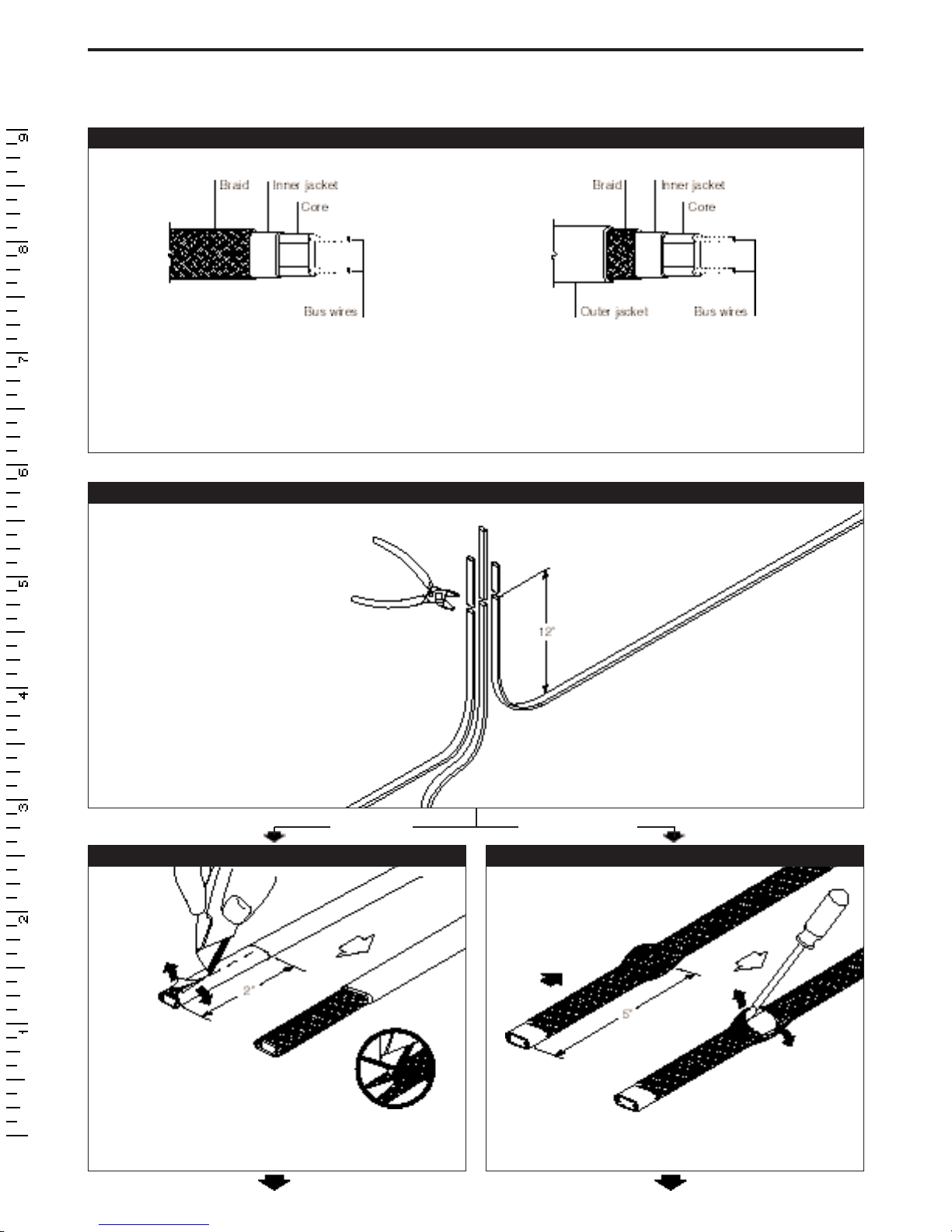
1Identify heating cable
2
Installation Instructions
H910 Splice and Tee Kit
2For all heating cables
3a For H612 and H622 heating cables only 3b For H311, H611, and H621 heating cables only
WinterGard H311, H611, H621
Heating cables with braid
but no outer jacket
WinterGard H612, H622
Heating cables with both
braid and outer jacket
Note: Illustrations generally show a heating cable with both braid and an outer jacket.
Cables with no outer jacket will look slightly different.
• Allow 12 inches of extra
heating cable as shown.
If necessary, trim cables
evenly.
• Lightly score completely around
and then down outer jacket
2 inches from end.
• Bend heating cable to break
jacket at score, then peel off
outer jacket.
• Push braid back.
• Gently spread apart
braid as shown.
Note: Illustrations of the following
instructions all show a tee connection.
Perform splice connections the same
way but use only two heating cable
sections, not three as shown.
H612, H622 H311, H611, H621

3
Installation Instructions
H910 Splice and Tee Kit
4a For H612 and H622 heating cables only 4b For H311, H611, and H621 heating cables only
5For all heating cables 6For all heating cables
7For all heating cables
• Unravel the
braid back to
the outer jacket.
• Position braid on
same side of each
heating cable section.
• Straighten the braid and twist into a “pigtail.”
• Bend
heating cable
and work it
through
opening
in braid.
• Lightly score
completely
around and
down inner
jacket 1 inch
from end.
• Bend heating cable to
break jacket at score,
then peel off inner
jacket.
• Notch core at the end. • Twist back and
peel bus wires
from core.
• Score between bus
wires at base jacket.
• Bend core to break it
free at base
jacket.
• Peel core and any
remaining material
from bus wires.
Repeat Steps 2–7 for
other heating cable
sections.
• Position braid on same side of each heating cable section.
• Straighten the braid and twist into a “pigtail.”

4
Installation Instructions
H910 Splice and Tee Kit
8For H612 and H622 heating cables only 9For all heating cables
10 For all heating cables
11 For all heating cables
• Remove release
paper from mastic
strip.
• Wrap a piece of
mastic around the
outer jacket on
each heating
cable section. • Pinch the mastic in
the center to com-
pletely seal the core
at the end of each
heating cable.
• Remove release
paper from mastic
strip.
• Wrap a piece of
mastic around the
end of each
heating cable
section and
position as shown.
• Carefully align the heating
cable sections and place
them together.
• Press mastic strips
firmly together. • Fasten with a cable
tie at each of the two
positions shown.
• Twist the braid
pigtails together.
• Slide the uninsulated crimp
over braid to within 1/4" of
heating cable as shown.
• Crimp the braid, using the
Ideal crimp tool. • Cut off the extra braid.

5
Installation Instructions
H910 Splice and Tee Kit
12 For H612 and H622 heating cables only
13 For all heating cables 14 For all heating cables
15a For H612 and H622 heating cables only 15b For H311, H611, and H621 heating cables only
• Fold the crimped braid back against the
heating cables.
• Wrap black cloth tape evenly around crimp
and heating cables. Cover crimp completely.
• Select one bus wire
from each cable
section and twist the
wires together.
• Position one 6-inch-
long heat-shrinkable
tube as shown.
• Measure 4 1/2 inches from end of
cap and mark cable. Position the
6-inch-long heat-shrinkable tube
as shown.
• Slide heat-shrinkable cap
over bus wire crimps.
• It is not necessary to shrink cap.
• Use insulated bus
wire crimps and T&B
crimp tool to crimp
each set of bus wires
together.
• Repeat with
remaining bus
wires.
Note:
Be careful
not to
twist
together
bus wires from the
same heating cable.

6
Installation Instructions
H910 Splice and Tee Kit
17a For all installations
except
gutter/downspout 17b For H612 and H622 gutter/downspout installations
16a For H612 and H622 heating cables only 16b For H311, H611, and H621 heating cables only
• Shrink the tube completely. Start at end
farthest from the cap and work toward the
open end.
• Keep heating after tube has shrunk, to melt
adhesive and mastic inside tube. Total heating
time should be about 5 minutes.
• Shrink the tube completely. Start at end
farthest from the cap and work toward the
open end.
• Keep heating after tube has shrunk, to melt
adhesive and mastic inside tube. Total heating
time should be about 5 minutes.
• Immediately after shrinking,
pinch the end of the tube with
needle nose pliers until the
end stays sealed; this
normally takes
10 seconds.
• After the connection has cooled, fold
over the connection and fasten it with
the third cable tie. • Secure heating cable with downspout
hanger (H904).
• Fasten clamp tie to center of connection.
• Use a hammer, nail, and clamp tie to secure
connection and keep it off the gutter bottom
as shown.
• Immediately after shrinking,
pinch the end of the tube with
needle nose pliers until the
end stays sealed; this
normally takes
10 seconds.
Caution:
To avoid burns, allow
heated sections to cool
before touching.
Caution:
To avoid burns, allow
heated sections to cool
before touching.
Secure end of
connection to
heating cable.

7
Installation Instructions
H910 End Seal (for tee connections only)
Note: The end seal is designed to be installed only once; it cannot be removed from the heating cable once installed. Do not use until ready
for final installation.
1End Seal for H612 and H622 1End Seal for H311, H611, and H621
2 2
3 3
4
• Remove the outer jacket.
• Do not cut or damage inner jacket.
• Push the braid back 2 inches from the
cable end.
• Slide the braid up against the end seal and secure
with the 6-inch length of tape provided.
• Firmly push end seal onto the cable (at least 1 1/2 inches).
Some gel may ooze out.
• Do not twist or try to remove the end seal during or after
insertion. Do not reuse an end seal.
• Firmly push end seal onto the cable (at least 1 1/2 inches).
Some gel may ooze out.
• Do not twist or try to remove the end seal during or after
insertion. Do not reuse an end seal.
• Unravel and remove
exposed braid.
• Cleanly cut off the end of the cable.
• Score down and around outer
jacket 1 inch from the end.
• Cleanly cut off the end of the cable.

©1997, 1998 Raychem Corporation Printed in USA (Y5129) H55073 (PN 585033) 8/98
WinterGard is a trademark of Raychem Corporation.
All information, including illustrations, is believed to be reliable. Users, however, should
independently evaluate the suitability of each product for their application. Raychem
makes no warranties as to the accuracy or completeness of the information, and
disclaims any liability regarding its use. Raychem’s only obligations are those in the
Raychem Standard Terms and Conditions of Sale for this product, and in no case will
Raychem be liable for any incidental, indirect, or consequential damages arising from
the sale, resale, use, or misuse of the product. Specifications are subject to change
without notice. In addition, Raychem reserves the right to make changes—without
notification to Buyer—to processing or materials that do not affect compliance with
any applicable specification.
Table of contents
Popular Adapter manuals by other brands


Allen-Bradley
Allen-Bradley POINT I/O ControlNet 1734-ACNR installation instructions

auna
auna 10030313 manual

TPCAST
TPCAST VIVE User Guide on Installation

Konexx
Konexx Office Konnector Office Konnector user guide

Devolo
Devolo dLAN 500 AVtriple+ Installation

Airlink101
Airlink101 AWLL6077 Quick installation guide


