RCA MRM400 User manual

VHF Marine Two-Way Radio

TO USER:
Thank you for purchasing this marine radio. You will find
the professional and human oriented design of the trans-
ceiver during use. Please read all instructions carefully
and completely before using the transceiver.
CAUTION
Never use the Distress call when your ship or a person is not in
an emergency.
Do not use or place the transceiver in areas with heat, humidity
and dust.
The working voltage for the transceiver is 13.8V. If the power
source is 24V, please use a power converter (24V convert to
13.8V), or the transceiver won’t work.
Never directly connect to AC220V, this will ruin the transceiver.
If an abnormal odor or smoke is detected coming from the trans-
ceiver, turn off the power immediately.
Do not transmit before connecting the antenna, this will ruin the
transceiver.
After long time use, the heating panel becomes hot, that is nor-
mal state.

PREPARATION
Supplied accessories.............................................................................1
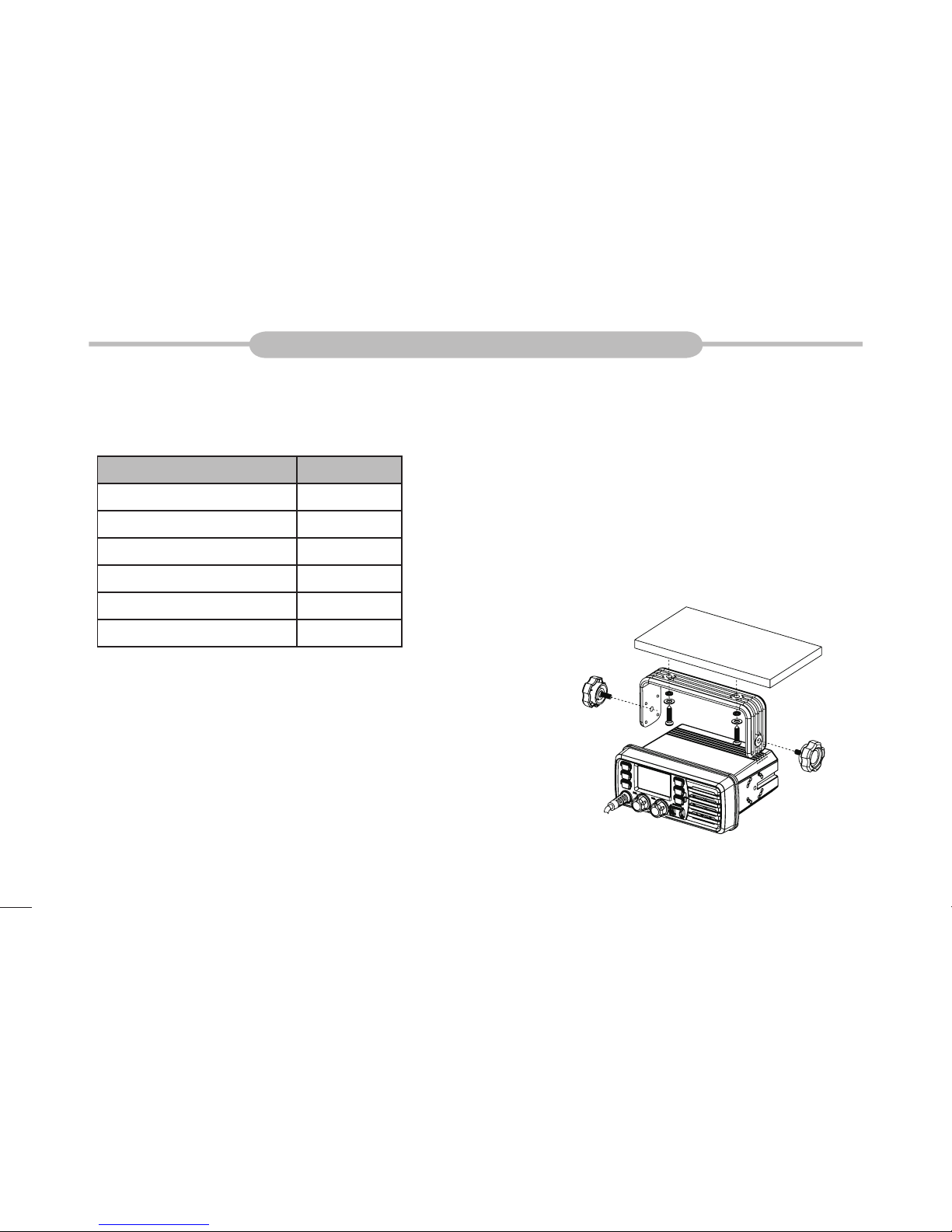
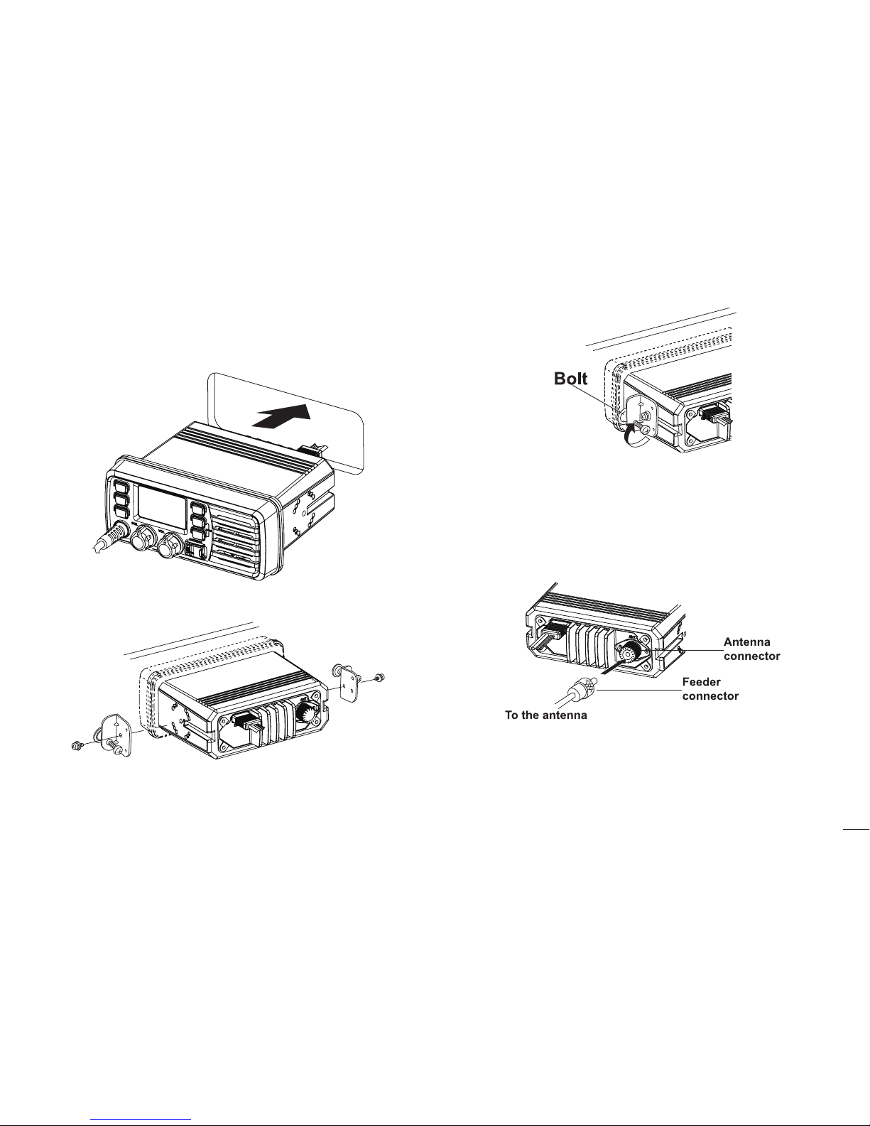
Transceiver mounting............................................................................1
Antenna connection...............................................................................2
Connections...........................................................................................2
Dimensions............................................................................................3
PANEL DESCRIPTION
Front panel ............................................................................................4
Microphone............................................................................................5
Function display.....................................................................................5
BASIC OPERATION
Power ON / OFF....................................................................................7
Receiving and transmitting....................................................................7
Channel group selection........................................................................7
Channel selection..................................................................................7
Call channel programming.....................................................................8
Channel comments................................................................................9
Microphone lock function.......................................................................9
Display backlighting...............................................................................9
AquaQuake water draining function ......................................................9
SCAN OPERATION
Scan types............................................................................................10
Setting TAG channels...........................................................................10
Starting a scan......................................................................................10
DUAL-WATCH / TRI-WATCH
Description............................................................................................11
Operation..............................................................................................11
CONTENTS
DSC OPERATION
MMSI code programming.....................................................................12
MMSI code check.................................................................................12
DCS address ID....................................................................................12
Distress call..........................................................................................13
Individual call........................................................................................14
Group call.............................................................................................16
All Ships call.........................................................................................17
Geographical Area call .........................................................................18
Position indication.................................................................................18
SET MODE
Set mode programming........................................................................21
Set mode items.....................................................................................21
CHANNEL LIST ..................................................................................23
SPECIFICATIONS................................................................................24
TROUBLESHOOTING.........................................................................24

1
Supplied accessories
The following accessories are supplied:
ITEM QTY
DC power cable 1
Spare fuse 1
Mounting bracket 1
Screws for mounting bracket 1
Microphone hanger 1
Instruction manual 1
Transceiver mounting
Using the supplied mounting bracket
The universal mounting bracket supplied with your transceiver allows overhead
or dashboard mounting.
Fix the mounting bracket to shelf or dashboard with the supplied screws and1. mount the transceiver to the mounting bracket with the knob bolts.
Mount the transceiver so that the face of the transceiver is at 90°to your line2. of sight when operating it and tighten the knob bolts so that the transceiver
is securely mounted.
You may use a spongy cushion between the transceiver and
mounting bracket to reduce the vibration.
PREPARATION

2
Embedded mounting
Cut a hole into the instrument panel (or wherever you plan to mount the1. transceiver).
Slide the transceiver through the holes as shown below.2.
Attach the clamps on either side of the transceiver with 2 supplied bolts.3.
Tighten the end bolts on the clamps so that the clamps press firmly against4. the inside of the instrument control panel.
Antenna connection
Please connect an antenna before transmitting. Select the antenna with the relative
frequency and connect on the ANT antenna connector. Use the antenna and low
loss concentric with the same natural impedance 50Ω.
Transmitting without an antenna may damage the trans-
ceiver.
Connections
After connecting the DC power cable, GPS receiver lead and external speaker lead,
cover the connector and leads with an adhesive tape as below, to prevent water
seeping into the transceiver.

3
External speaker lead
Connect to an external speaker.
GPS receiver lead
Connect to a GPS receiver for position indication.
An NMEA0183 ver.2.0 or 3.01 (sentence formatters RMC, GGA, GNS,
GLL) compatible GPS receiver is required.
DC power connector
Connect the supplied DC power cable from this connector to an external 13.8V
DC power source. Do not connect to 24V storage battery.
Fuse replacement
One fuse is installed in the supplied DC power cable. If a fuse blows or the trans-
ceiver stops functioning, track down the source of the problem, if possible, and
replace the damaged fuse with a new, rated one.
Please power off before replacing the fuse, the required fuse is
DC15A/32V.
Dimensions

4
PANEL DESCRIPTION
Front panel
Channel 16 / Call Channel Key [16]1.
→Push to select Channel 16.
→Push and hold for 1 sec. to select call channel.
“CALL” appears when the call channel is selected.
→While pushing and holding [CH/WX], push [16] to enter the channel
comments programming condition.
→Push to move the cursor backward.
→While turning power ON, push [16] to enter set mode.
Channel / Weather Channel Key2.
→Select and toggle the regular channel and weather channel when pushed
momentarily.
→Push and hold for 1 sec. to start Dualwatch or Tri-watch.
→Push to stop Dualwatch or Tri-watch when either is activated.
→Push to move the cursor forward.
3. DSC / Position Key
→Push to enter DSC menu.
→Push and hold for 1 sec. to show the current position from a GPS receiver.
4. Squelch Control [SQL]
Rotate to set the squelch threshold level.
5. Power / Volume Control [VOL]
Rotate to turn the transceiver power ON and OFF and adjusts the audio level.
6. Distress Key [DISTRESS]
Push and hold for 5 sec. to transmit a Distress call.
7. Scan / Tag Key [SCAN]
→Push to start or stop the normal or priority scan.
→Push and hold for 1 sec. to set or clear the displayed channel as a TAG
(scanned) channel.
The favorite channels are set by the TAG channel setting.
→Push and hold [HI/LO] and [SCAN] to clear all TAG channels in the selected
channel group.
Repeat above procedure to set all TAG channels.
8. [▲][▼] / [U/I/C]
→Select the operating channels, set mode settings, etc.
→While pushing and holding [SCAN], push [▲] or [▼] to adjust the brightness
of the LCD and key backlight.
→Select one of three channel groups in sequence when both keys are
pushed.
→While turning power ON, push and hold both keys to activate theAquaQuake
function.

5
Microphone
[PTT]1.
Push and hold to transmit; release to receive.
Channel UP / DOWN Keys[▲]/[▼]2.
→Push either key to change the operating channel, set mode settings, etc.
→When the favorite channel function is turned ON, push either key to select
the favorite channels in the selected channel group in sequence.
Transmit Power Key [HI/LO]3.
→Push to toggle the power high and low.
Some channels are set to low power only.
→While push and hold [HI/LO], turn power ON to toggle the microphone
lock function ON and OFF.
Function display
Channel Number Readout1.
→Indicate the selected operating channel number. (Refer to channel list)
→In set mode, indicate the selected condition.
Channel Group Indicator2.
Indicate whether a U.S.A. “U”, International “I” or Canadian “C” channel is
in use.
Channel Comment Indicator3.
→Channel comment appears if programmed.
→“LOW BATTERY” scrolls when the battery voltage drops approx. 10.8V
DC or below.
→“SC” blinks during priority scan; “SCAN” blinks during normal scan.
→“DW” blinks during Dualwatch; “TW” blinks during Tri-watch.
DSC Indicators4.
→“DSC” appears when a DSC call is received.
→“POS REPLY” appears when a position reply call or position report reply

6
call is received.
GPS Indicator5.
→Appears while valid position data is received.
→Blinks when invalid position data is received.
→Disappears when no GPS receiver is connected.
Weather Channel Indicator6.
→“WX” appears when a weather channel is selected.
→“WX ALT” appears when the weather alert function is in use; blinks when
an alert tone is received.
Duplex Indicator7.
Appears when a duplex channel is selected.
Low Power Indicator8.
Appears when low power is selected.
Call Channel Indicator9.
Appears when the call channel is selected.
TAG Channel Indicator10.
Appears when a TAG channel is selected.
Busy Indicator11.
Appears when receiving a signal or when the squelch opens.
Transmit Indicator12.
Appears while transmitting.

7
BASIC OPERATION
Power ON / OFF
Rotate [VOL] clockwise to turn power on;1.
Rotate [VOL] counter-clockwise to turn power off.2.
Receiving and transmitting
Transmitting
Push1. [HI/LO] on the microphone to select the output power if necessary.
”LOW” appears when low power is selected.
Choose low power for short range communication, choose high power for
longer distance communication.
Some channels are for low power only.
Push and hold2. [PTT] to transmit, then speak into the microphone.
“TX” appears.
Channel 70 cannot be used for transmission other than DSC.
Release3. [PTT] to receive.
Note:
Do not transmit before connecting the antenna, this will ruin the trans-
ceiver.
The TOT (Time-out Timer) function inhibits continuous transmission over a
preset time period after the transmission starts.
Receiving
Set the audio and squelch levels.1. Rotate2. [SQL] fully counterclockwise in advance.
Rotate3. [VOL] to adjust the audio output level.
Rotate4. [SQL] clockwise until the noise disappears.
“When receiving a signal, ””appears and audio is emitted from the
speaker.
Channel group selection
The transceiver is pre-programmed with 59 U.S.A., 59 international and 63 Cana-
dian channels. These channel groups may be specified for the operating area.
Push [CH/WX] to select a regular channel.1. If a weather channel appears, push[CH/WX] again.
Push2. [U/I/C] (both [▲] and [▼] on the transceiver to change the channel
group, if necessary.
U.S.A., International and Canadian channel groups can be selected in
sequence.
Push3. [▲] or [▼] to select a channel.
””appears for duplex channels.
Channel selection
Channel 16
Channel 16 is the distress and safety channel. It is used for establishing initial
contact with a station and for emergency communication. Channel 16 is moni-
tored during both Dual-watch and Tri-watch. While standing by, you must monitor
Channel 16.

8
Push1. [16] momentarily to select Channel 16.
Push2. [CH/WX] to return to the condition before selecting Channel 16, or
push [▲] or [▼] to select operating channel.
Convenient:
When the favorite channel function is turned ON, [▲]/[▼] keys on the micro-
phone select the favorite channels in the selected channel group in sequence
when pushed.
The favorite channels are set by the TAG channel setting. (P.10)
Channel 9 (Call channel)
Each regular channel group has a separate leisure-use call channel (Channel 9;
default). The call channel is monitored during Tri-watch.
Push and hold1. [16] for 1 sec. to select the call channel of the selected chan-
nel group. “CALL” and call channel number appear.
Push2. [CH/WX] to return to the condition before selecting call channel, or
push [▲] or [▼] to select a channel.
Weather channels
The transceiver has 10 pre-programmed weather channels. The transceiver can
automatically detect a weather alert tone on the selected weather channel while
receiving the channel or during scanning.
Push [CH/WX] once or twice to select a weather channel.1.
“WX” appears when a weather channel is selected.
“WX ALT” appears when the weather alert function is in use.
Push2. [▲] or [▼] to select a channel.
Call channel programming
Call channel is used to select Channel 9 (default), however, you can program the
call channel with your most offer-used channel in each channel group for quick
recall.Push1. [U/I/C] (both [▲] and [▼] on the transceiver several times to select the
desired channel group (U.S.A., International or Canada) to be programmed.
Push and hold2. [16] for 1 sec. to select the call channel of the selected chan-
nel group.
“CALL” and call channel number appear.
Push and hold3. [16] again for 3 sec. (until a long beep changes to 2 short
beeps) to enter call channel programming condition.
Channel number starts blinking.
Push4. [▲] or [▼] to select the desired channel.
Push5. [16] to program the displayed channel as the call channel.
Push[CH/WX] to cancel.

9
microphone. This prevents accidental channel
changes and function access.
→While pushing and holding [HI/LO] on the
microphone, turn power ON to toggle the
microphone lock function ON and OFF.
Display backlighting
The function display and keys can be backlit
for better visibility under low light conditions.
→While pushing and holding [SCAN], push [▲] or [▼] to adjust the brightness of
the LCD and key backlight.
The backlight is selectable in 3 levels and OFF.
AquaQuake water draining function
AquaQuake helps drain water away from the speaker housing (water that might
otherwise muffle the sound coming from the speaker). The transceiver emits a vi-
brating noise when this function is being used.
While pushing and holding1. [▲] and [▼], turn power ON.
“AQUA QUAKE” appears.
A low beep tone sounds while2. [▲] or [▼] keys are held to drain water, re-
gardless of [VOL] control setting.
The transceiver never accepts a key operation while theAquaQuake func-
tion is activated.
Channel comments
Memory channels can be labeled with a unique alphanumeric ID of up to 10 char-
acters each. More than 6 characters comment scrolls automatically at the channel
comment indicator after the channel selection.
Capital letters, small letters (except f, j, k, p, s, v, x, z), 0 to 9, some symbols (=*+ - .
/) and space can be used.
Select the desired channel.1. Cancel Dualwatch, Tri-watch or scan in advance.
While pushing2. [CH/WX], push [16] to edit the channel comment.
A cursor and the first character start blinking alternately.
Pushing3. [▲] or [▼] to select the desired character.
Push[16] or [CH/WX] to move the cursor forward or backward, respec-
tively.
Repeat step4. ③to input all characters.
Push5. [DSC] to input and set the comment.
Push[SCAN] to cancel.
The cursor and the character stop blinking.
Microphone lock function
The microphone lock function electrically locks [▲] and [▼] keys on the supplied

10
Scan types
The transceiver has priority scan and normal scan. (Refer to set mode program-
ming).
When the weather alert function is turned ON, the previously selected (last used)
weather channel is also checked while scanning.
Set the TAG channels (scanned channels) before scanning. Clear the TAG chan-
nels which inconveniently stop scanning.
Normal scan:
Normal scan searches through all TAG channels in sequence. Channel 16 is not
checked unless Channel 16 is set as a TAG channel.
Priority scan:
Priority scan searches though all TAG channels in sequence while monitoring
Channel 16.
Setting TAG channels
For more efficient scanning, add desired channels as TAG channels or clear the
TAG for unwanted channels.
Channels that are not tagged will be skipped during scanning.
Setting / clearing a single tagged channel
Push1. [U/I/C] (both [▲] and [▼]) several times to select the desired channel
group.
Select the desired channel to be set as a TAG channel.2. Push and hold3. [SCAN] for 1 sec. to set the displayed channel as a TAG
channel.
””appears in the display.
To cancel the TAG channel setting, repeat step4. ③.
””disappears.
Setting / clearing all tagged channels
While pushing and holding1. [HI/LO] on the microphone, push [SCAN] for 3
sec. to clear all TAG channels in the selected channel group.
Repeat above procedure to set all TAG channels.2.
Starting a scan
Set scan resume timer in advance using Set mode.
Push1. [SCAN] to start priority or normal scan.
“SC” blinks during priority scan; “SCAN” blinks during normal scan.
Channel 16 is monitored during priority scan.
Push[▲] or [▼] to change the scanning direction.
A beep tone sounds and “SC 16” blinks at the channel comment indicator
when a signal is received on Channel 16 during priority scan.
To stop the scan, push2. [SCAN].
SCAN OPERATION

11
Description
The transceiver has Dualwatch and Tri-watch.
Dualwatch monitors Channel 16 while you are receiving on another channel.
Tri-watch monitors Channel 16 and the call channel while receiving another chan-
nel.
Operation
Select Dualwatch or Tri-watch in set mode.1. Select the desired channel.2. Push and hold3. [CH/WX] for 1 sec. to start Dualwatch or Tri-watch.
“DW” blinks during Dualwatch; “TW” blinks during Tri-watch.
A beep tone sounds when a signal is received on Channel 16.
To cancel Dualwatch or Tri-watch, push4. [CH/WX].
DUAL-WATCH / TRI-WATCH

12
MMSI code programming
The 9-digit MMSI (Maritime Service Identity: DSC self ID) code can be programmed
at power ON.
Rotate1. [VOL] to turn power OFF.
While pushing and holding2. [DSC], turn power ON to enter MMSI code pro-
gramming condition.
After the display appears, release3. [DSC], a cursor starts blinking.
Edit the specified MMSI code by pushing4. [▲] or [▼].
Push[16] or [CH/WX] to move the cursor forward or backward, respec-
tively.
Input 9-digit code, then push5. [DSC] to set the code.
Returns to the normal operation.
Note:
This code programming can be performed only twice. After the code pro-
gramming, it can be changed only by your dealer or distributor.
MMSI code check
The 9-digit MMSI (DSC self ID) code can be checked.
Push1. [DSC] to enter the DSC menu.
Push2. [▲] or [▼] to select “MMSI” and push [DSC].
Check the 9-digit MMSI (DSC self ID) code.3. The MMSI code is displayed and scrolls at the channel comment indica-
tor.
Push4. [DSC] to return to the normal operation.
DCS address ID
A total of 30 DSC address IDs (9-digit) can be programmed and named with up to
5 characters.
Programming address ID
Push1. [DSC] to enter the DSC menu.
Push2. [▲] or [▼] to select “ADDRESS”, and push [DSC].
Push3. [▲] or [▼] to select “ADD”, and push [DSC].
DSC OPERATION

13
Push4. [▲] or [▼] to input 9-digit of the appropriate address ID.
Push [16] or [CH/WX] to move the cursor forward or backward, respec-
tively.
Push [SCAN] to cancel and exit the condition.
Note: 1st digit “0”is fixedfora group ID.When you input 1stdigit“0” andother8digits,
the ID is automatically registered as a group ID.
After inputting 9-digit ID, push5. [DSC] to input 5 characters ID name using
[▲] or [▼].
Push [16] or [CH/WX] to move the cursor forward or backward, respec-
tively.
P ush [SCAN] to cancel and exit the condition.
Push6. [DSC] to program and exit the DSC menu.
Deleting address ID
Push [DSC] to enter the DSC menu.1.
Push [▲] or [▼] to select “ADDRESS” and push [DSC].2.
Push3. [▲] or [▼] to select “DEL”, then push [DSC].
When no address ID is programmed, “NO ID” is displayed.
Push4. [▲] or [▼] to select the desired ID name for deleting and push [DSC],
“READY” appears.
Distress call
A Distress call should be transmitted if, in the opinion of the master, the ship or a
person is in distress and requires immediate assistance.
Note: Never use the Distress call when your ship or a person is not in an emer-
gency. ADistress call can be used only when immediate help is needed.
Transmitting a Distress call
While opening the key cover, push1. [DISTRESS] for 5 sec. to transmit the
Distress call.
Emergency channel (Channel 70) is automatically selected and the Dis-
tress call is transmitted.
After transmitting the call, the transceiver waits for an acknowledgment call2. on Channel 70.
The Distress call is automatically transmitted about every 4 minutes.
“DSC REPEAT” scrolls at the channel comment indicator.

14
After receiving the acknowledgment, reply using the microphone.3. “RCV DISTRESS ACK” scrolls at the channel comment indicator.
Push and hold4. [DISTRESS] for 5 sec. to transmit a re-newed Distress call,
if desired.
Push any key except5. [DISTRESS] to cancel the ‘call repeat’ mode.
Note: A distress alert contains:
Kinds of distress: Undesignated distress
Position data: GPS position data held until receiving an ‘acknowledge-
ment’.
Receiving a Distress call
While monitoring Channel 70 and a Distress call is received:
The emergency alarm sounds.1. Push any key to stop the alarm.
“DSC” appears and “RCV DISTRESS” scrolls at the channel comment indi-2. cator, then Channel 16 is automatically selected.
Continue monitoring Channel 16 as a coast station may require assistance.3.
Receiving a Distress acknowledgement
While monitoring Channel 70 and a Distress acknowledgement to other ship
is received:
The emergency alarm sounds.1. Push any key to stop the alarm.
“DSC” appears and “RCV DISTRESS ACK” scrolls at the channel com-2. ment indicator, then Channel 16 is automatically selected.
Receiving a Distress Relay call
While monitoring Channel 70 and a Distress Relay acknowledgement is re-
ceived:
The emergency alarm sounds.1. Push any key to stop the alarm.
“DSC” appears and “RCV RELAY” scrolls at the channel comment indicator,2. then Channel 16 is automatically selected.
Individual call
The Individual call function allows you to transmit a DSC signal to a specific ship
only.
Transmitting Individual call
Push [DSC] to enter the DSC menu.1. “INDIVIDUAL” scrolls at the channel comment indicator.

15
Push2. [DSC] to select the desired pre-programmed individual address using
[▲] or [▼], then push [DSC].
The ID code for the Individual call must be set in advance.
Push3. [▲] or [▼] to select a desired intership channel, push [DSC].
Intership channels are already preset into the transceiver in recommend-
ed order.
Channel 70 is selected and “READY” appears after pushing[DSC].
Push4. [DSC] to transmit the Individual call.
If Channel 70 is busy, the transceiver stands by until the channel becomes
clear.
After transmitting the Individual call, standby on Channel 70 until an acknowl-5. edgement is received.
“WAIT ACK” scrolls at the channel comment indicator.
When the acknowledgement ‘Able to comply’ is received, the specified chan-6. nel (in step ③) is selected with beeps automatically. Or, when the acknowl-
edgement ‘Unable to comply’ is received, the display returns to the operated
channel (before entering the DSC menu) with beeps.
“RCV ABLE ACK” OR “RCV UNABLE ACK” scrolls at the channel com-
ment indicator.
Push and hold7. [PTT] to communicate your message to the responding ship
when ‘Able to comply’ is received.
Transmitting Individual acknowledgement
When receiving an Individual call, you can transmit an acknowledgement
(‘Able to comply’ or ‘Unable to comply’) by using the on screen prompts (refer
to “Receiving an Individual call”). You can also send an acknowledgement
through the menu system as follows.
Push1. [DSC] to enter the DSC menu.
Push2. [▲] or [▼] to select “INDV ACK” and push [DSC].
“INDV ACK” item appears after an Individual call is received.
“INDV ACK” item disappears if another call is received after the Individual
call.
The Individual acknowledgement can be transmitted to the last received
Individual call only.
Push3. [▲] or [▼] to select the acknowledgement “ABLE” or “UNABL”.

16
Push4. [DSC] to enter the standby condition for Individual acknowledgement
call.
“READY” appears at the channel comment indicator.
Push5. [DSC] to transmit the acknowledgement to the selected station.
After the Individual acknowledgement has been transmitted, the display6. changes to the channel specified by the calling station automatically when
“ABLE” is selected.
Receiving an Individual call
While monitoring Channel 70 and an Individual call is received:
The emergency alarm or beeps sound depending on the received category.1. “DSC” appears and “RCV INDIVIDUAL” scrolls at the channel comment in-2. dicator.
Push any key to stop beep.3. Push4. [DSC] to reply the call and select the channel specified by the calling
station for voice communication; Push any other key to ignore the Individual
call.
Group call
The Group call function allows you to transmit a DSC signal to a specific group
only.
Transmitting Group call
Push1. [DSC] to enter the DSC menu.
Push2. [▲] or [▼] to select “GROUP”, and push [DSC].
Push3. [▲] or [▼] to select the desired pre-programmed group address, and
push [DSC].
The ID code for the Group call must be set in advance.

17
Push4. [▲] or [▼] to select the desired intership channel, and push [DSC].
Channel 70 is selected and “READY” appears.
Push5. [DSC] to transmit the Group call.
If Channel 70 is busy, the transceiver stands by until the channel become
clear.
After the Group call has been transmitted, the display changes to the previ-6. ously specified channel.
Push and hold7. [PTT] to communicate your message to the responding
ship.
Receiving a Group call
While monitoring Channel 70 and a Group call is received:
The emergency alarm or beeps sound depending on the received category.1. “DSC” appears and “RCV GROUP” scrolls at the channel comment indica-2. tor.
Push any key to stop beep.3. Push4. [DSC] to select the channel specified by the calling station for voice
communication; Push any other key to ignore the Group call.
All Ships call
The All Ships call function allows you to transmit a DSC signal to all
ships.
Transmitting All Ships call
Large ships use Channel 70 as their ‘listening channel’. When you want to an-
nounce a message to these ships, use the ‘All Ships call” function.
Push1. [DSC] to enter the DSC menu.
Push2. [▲] or [▼] to select “ALL SHIPS”.
Push3. [DSC] to enter the standby condition for All Ships call.
Channel 70 is selected and “READY” appears.
Push4. [DSC] to transmit the All Ships call.
Other manuals for MRM400
1
Table of contents
Other RCA Marine Radio manuals
Popular Marine Radio manuals by other brands

Uniden
Uniden UM425 owner's manual

West Marine
West Marine VHF650 owner's manual

Cobra Marine
Cobra Marine MARINE MR F80B-D owner's manual

Cobra Marine
Cobra Marine MR HH500 FLT BT EU owner's manual

Benthos
Benthos 865-A INSTRUCTIONS FOR THE INSTALLATION, OPERATION AND MAINTENANCE

Allegion
Allegion Simons Voss Technologies TRA2.G2.EX quick guide