RDT FloodMaster RS-096-MK6 User manual

Plenum-Rated Water Leak Detection /
HVAC & AC Condensate Pan Overow Alarm
with Step-Down Transformer & Plenum-Rated Wires
Congratulations on your purchase of a FloodMaster RS-096-MK6 plenum-rated plumbing leak
detection and HVAC/AC condensate pan overow alarm from Reliance Detection Technologies.
This product is designed to alert you if a leak or near overow condition is detected.
To ensure proper installation and to maximize the performance of your RS-096-MK6 water leak
detection system, please read this manual thoroughly before installing or operating the system.
NOTE: This installation and operating manual contains important information about the operation of the
RS-096-MK6 system. If this system is being installed for use by a different user, please be sure a copy of
this manual is left with the system for future reference.
www.RelianceDetection.com Toll-Free: 888-771-4929
RS-096-MK6 System Components (included in kit):
1 – Receiver box
1 – Water sensor with 8’ lead wire
1 – Metal plate for sensor placement
1 –
Step-down transformer (120, 208, 240V AC
to 24V AC ) and mounting plate
RS-096-MK6
Warning: For indoor use only.

INSTALLATION INSTRUCTIONS
1. Mount the receiver box in the desired location using supplied two-sided tape.
2. The receiver connector comes prewired with basic connections to the power supply and the
sensor. Using an appropriate screwdriver, make any additional desired electrical connections
for output contacts or additional sensors per Figure 1. (Note: additional sensors can be
connected to either 6 & 7 or 8 & 9, as wiring space allows.) Then snap the terminal wiring block
into the receiver housing at the mating slot provided.
3. Turn off the main power. Wire the appropriate inputs to the main power source. Wire the blue
and yellow wires (24V AC output) to the plenum wire that is prewired to the power input of the
contact plug. Turn on the main power. The green “Power” indicator light on the receiver will
turn on.
4. Place the sensor(s) where leaking water is most likely to rst accumulate (such as the base of
a washing machine, hot water heater, under sink, etc.), or in an HVAC/AC condensate pan to
monitor for potential overow.
The sensor is magnetic and can be installed horizontally or vertically in conjunction with the
metal plate – see Figure 2. Install the sensor ush to the oor for immediate alarm or at the
desired overow alarm level.
• Clean the desired location area to ensure the surface is clean for optimum plate adhesion.
• Peel the backing off the metal plate to reveal the adhesive and stick in place.
• Place the sensor on the plate at the desired height, allowing the magnets to secure it
in place.
Note: The sensor features a through-hole that can be used to screw it onto a surface if a more
permanent installation is desired or necessary.
5. Function Test the system as follows:
• Place the sensor on a wet paper towel. The audible alarm will sound.
• Remove the sensor from the paper towel, dry the contact points, and place it back in the
desired location on the metal plate.
• If necessary, press and release the “Reset” button on the receiver to reset the system’s
NO/NC dry contact outputs.
TRANSFORMER WIRING INSTRUCTIONS
The supplied transformer has multiple input taps to accommodate different line voltages. If the
existing line voltage you have at your facility is:
120V AC – The WHITE wire from the transformer should be connected to the hot leg of the
input voltage and the black wire to the neutral leg.
208V AC – The RED wire from the transformer should be connected to the hot leg of the input
voltage and the black wire to the neutral leg.
240V AC – The ORG wire from the transformer should be connected to the hot leg of the input
voltage and the black wire to the neutral leg.
The GREEN wire in all cases must be connected to EARTH GROUND.
Each wiring combination as stated above yields the same 24V AC output across the BLUE and
YELLOW wires of the secondary winding of the transformer.
See back cover for Transformer Mounting Instructions.
WHITE
RED
BLACK
Sensor leads not polarized.
TRANS-
FORMER
MAIN POWER IN
24 VAC OUT
120
VAC WHT GRN
208
VAC RED
240
VAC ORG
C
OM BLK
BLUYEL
BLK RED
2.56
Ø .12 THRU
1.77
.02
RS-096-MK6
WATER
ALARM KIT
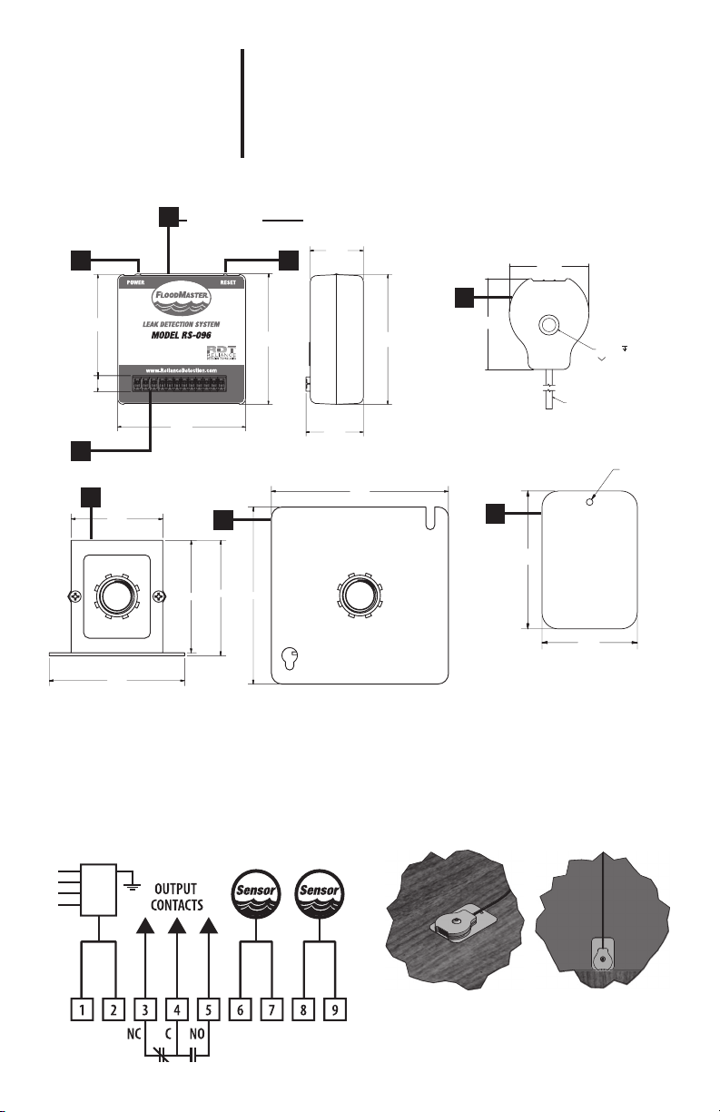
1. Receiver box
2. Power LED
3. Reset button
4. Wiring terminal block
mating slot
5. Water sensor
6. Metal plate
7. Step-down transformer
8. Transformer mounting plate
5
6
1.48
1.69
8 FT LEAD
.30
.04
PIN OFFSET
FROM SURFACE
Ø .25 .30
Ø .38 x 82°
FIGURE 1 –
WIRING DIAGRAM
FIGURE 2 –
SENSOR INSTALLATION OPTIONS
HORIZONTAL VERTICAL
1.08
2.61
2.65
.33
2.06
1.17
2.66
4
1FRONT VIEW SIDE VIEW
2 3
2.200
2.770
2.700
3.250
4.250
4.250
7
8

All specications subject to change without notice.
© Copyright 2020 Reliance Detection Technologies, LLC – A Madison Company
ECN # 11386, 07/2020, MF162, RevB
TRANSFORMER MOUNTING INSTRUCTIONS
The kit contains a cover plate for a standard junction box. The cover has a hole or knock out in
the center of it. The cover plate is designed such that the transformer can be mounted to it and
then screwed into the junction box.
1. In order to mount the transformer to the cover, carefully route the primary wires of the
transformer through the hole in the cover.
2. Tilt the cover so that the head of the retaining screw on the transformer is over the cover.
3. Back the screw out until the cover slips under the threaded end of the retaining screw.
4. Tighten the screw until the transformer is secured on the cover. The threaded end of the screw
is designed to press against the cover to hold the transformer in place.
OPTIONAL FEATURES AND CONNECTIONS:
See Figure 1 for wiring diagram.
Additional Water Sensors – For applications where a wider area of leak detection coverage is
desired, additional sensors can be added to the system. Wire additional sensors to terminal strip
pins 6 & 7 or 8 & 9. Additional sensors are sold separately; custom wire lengths available.
Security Panel Connection – Use for applications where connection to a home security system
or control panel is desired, or to turn off an HVAC unit to prevent further water accumulation in
the pan. Control of such a device may require an appropriate relay (not included).
This dry contact relay signal can be wired per your application requirements as follows:
Normally Closed Circuit – Terminal Pins 3 & 4 Normally Open Circuit – Terminal Pins 4 & 5
Press and release the “Reset” button after alarm to reset the signal.
OPERATION & SYSTEM RESET
In the event the system activates, locate the source of the leak or near overow, remove the
sensor from the water and dry the metal contacts. Correct the problem and replace the sensor
in the desired leak detection location. If necessary, press and release the “Reset” button on the
receiver to reset the system’s NO/NC dry contact outputs.
MAINTENANCE
Exercise (press and release) the “Reset” button on the receiver box annually to ensure correct
operation and to maintain product warranty status.
203-488-2684 or 888-771-4929
27 Business Park Drive, Branford, CT 06405
www.RelianceDetection.com [email protected]
NEED INSTALLATION OR SETUP ASSISTANCE?
Call toll-free: 888-771-4929 or visit www.RelianceDetection.com/support/RS-096
Table of contents


